Table of Contents
Advertisement
Quick Links
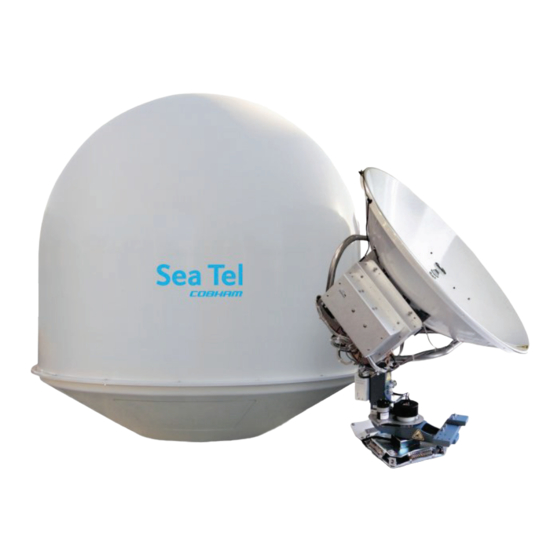
FOR SEA TEL 3011W-91 BROADBAND-AT-SEA
TRANSMIT / RECEIVE SYSTEM WITH SELECTABLE CO-POL OR
Sea Tel, Inc.
4030 Nelson Avenue
Concord, CA 94520
Tel: (925) 798-7979
Fax: (925) 798-7986
Web:
http://www.cobham.com/seatel
Sea Tel Inc is also doing business as Cobham Antenna Systems
January 30, 2012
INSTALLATION MANUAL
CROSS-POL RECEIVE
Sea Tel Europe
Unit 1, Orion Industrial Centre
Wide Lane, Swaythling
Southampton, UK S0 18 2HJ
Tel: 44 (0)23 80 671155
Fax: 44 (0)23 80 671166
Web:
http://www.cobham.com/seatel
Document. No. 136407 Revision A
Advertisement
Table of Contents
Troubleshooting

Related Manuals for Sea Tel 3011W-91


Summary of Contents for Sea Tel 3011W-91
-
Page 1: Installation Manual
Southampton, UK S0 18 2HJ Fax: (925) 798-7986 Tel: 44 (0)23 80 671155 Web: http://www.cobham.com/seatel Fax: 44 (0)23 80 671166 Web: http://www.cobham.com/seatel Sea Tel Inc is also doing business as Cobham Antenna Systems January 30, 2012 Document. No. 136407 Revision A... - Page 2 The Sea Tel Series 09 & 10 antennas will meet the off-axis EIRP spectral density envelope set forth in FCC 47 C.F.R. § 25.222(a)(1) when the input power density limitations, listed in our FCC Declaration, are met..
-
Page 5: Table Of Contents
Table of Contents 3011W-91 Installation Manual 1. 3011 SYSTEM CONFIGURATION(S) ............................... 1-1 1.1......................................1-1 YSTEM ABLES 1.2................................... 1-1 THER NPUTS TO THE YSTEM 1.3. 3011 ..........................1-1 IMPLIFIED BLOCK DIAGRAM OF A SYSTEM 1.4................................1-2 NTENNA ONFIGURATION 1.5. - Page 6 3011W-91 Installation Manual Table of Contents 3.7............................3-10 ONNECTING THE ELOW ECKS QUIPMENT 3.7.1. Connecting the ADE AC Power Cable ......................... 3-10 3.7.2. Connecting the BDE AC Power Cables ........................3-10 3.7.3. Connecting the ADE IF Coaxes ............................3-10 3.7.4.
- Page 7 Table of Contents 3011W-91 Installation Manual 9.1.2. You Observe “Home” Pointing is LEFT of the Bow-line: ..................9-2 9.1.3. You Observe “Home” Pointing is RIGHT of the Bow-line: ..................9-2 9.1.4. To Enter the HFO value in the DAC_2202: ........................9-3 9.2.
- Page 8 3011W-91 Installation Manual Table of Contents 14.7. S ................................... 14-2 ATELLITE EFERENCE 14.8. REMOTE PARAMETERS ..................................14-2 15. FUNCTIONAL TESTING ..................................15-1 15.1. ACU / A ................................15-1 NTENNA YSTEM HECK 15.2. L ............................. 15-1 ATITUDE ONGITUDE PDATE CHECK 15.3. H ....................................
- Page 9 ONSUMPTION 18.5. C ........................................... 18-5 ABLES 18.5.1. IF Signal Cables ..................................18-5 18.5.2. SBS/Synchro Gyro Compass Interface Cable (Customer Furnished) ............18-5 19. 3011W-91 TECHNICAL SPECIFICATIONS ..........................19-1 19.1. A 3011 ................................19-1 NTENNA EFLECTOR 19.2. SMW Q LNB ................................... 19-1 19.3.
-
Page 10: System Configuration(S)
3011 System Configuration(s) 3011W-91 Installation Manual 3011 System Configuration(s) The 3011 Stabilized Antenna system is to be used for Transmit/Receive (TX/RX) satellite communications, it is comprised of two major groups of equipment. These are the Above Decks Equipment (ADE) and the Below Decks Equipment (BDE). There will also be interconnecting cables between the ADE &... -
Page 11: Dual Antenna Configuration
3011W-91 Installation Manual 3011 System Configuration(s) 1.4. Dual Antenna Configuration Sometimes, due to very large blockage conditions, you may need to install a dual antenna configuration to provide uninterrupted services. Two full antenna systems are installed and the ACU control outputs are connected to an arbitrator switch panel which then is connected to the below decks equipment. -
Page 12: Dual Antenna Arbitrator
3011 System Configuration(s) 3011W-91 Installation Manual 1.5. Dual Antenna Arbitrator The Dual Antenna Arbitrator panel can pass LNB voltages (and handle 250-400 ma of current) and the RXIF signals on the RX connections. TXIF, Reference and BUC supply voltage can be passed through this arbitrator panel to the antenna, but it is not recommended that BUC power be supplied through the dual channel rotary joint of the antenna (a BUC power supply is provided on all Series 09 Antenna Pedestals). -
Page 13: Interface Requirements
(proper option files) and the ACU/PCU (setup parameters) are actually compatible for the intended satellite(s). 1.6.2. Interface requirements: 1.6.2.1. Hardware Sea Tel Antenna Control Units Model DAC2202 or DAC2302. Any Satellite modem manufacturer that is compatible with OpenAMIP CAT5 Patch cable 1.6.2.2. Software Sea Tel model DAC2202: ACU software version 6.06 or greater... -
Page 14: Site Survey
For Naval Engineering level information on this subject, please refer to Antenna Installation Guideline – Site Arrangement, document number 130040_A available on the Sea Tel Dealer Support Site. -
Page 15: Mounting Foundation
The height of the pedestal should be kept as short as possible, taking into account recommendations given in other Sea Tel Guidelines. The minimum height of the pedestal above a flat deck or platform to allow access into the radome for maintenance should be 0.6 meters (24 inches). -
Page 16: Mounting Height
2.5. Mast Configurations Sea Tel recommends the ADE be mounted on the ship in a location which has both a clear line-of-sight to the target satellites in all potential azimuth/elevation ranges and sufficient support against vibration excitement. If possible, mounting the ADE pedestal directly to ship deckhouse structures or other box stiffened structures is preferred. -
Page 17: Vertical Masts
3011W-91 Installation Manual Site Survey 2.5.1. Vertical Masts Vertical masts are a very ancient and common mast design. In essence, it is the mast derived from the sailing mast, adapted for mounting the ever-increasing array of antennae ships need to communicate with the world. -
Page 18: Truss Mast
For every 100 Kilograms of ADE weight over 250 Kilograms, the depth of the platform stiffeners should be increased by 50 millimeters and thickness by 2 millimeters. Sea Tel does not have a recommended arrangement for a truss mast – the variability of truss mast designs means that each installation needs to be evaluated separately. -
Page 19: Ade/Bde Coaxial Cables
3011W-91 Installation Manual Site Survey 2.8.1. ADE/BDE Coaxial Cables The first concern about the coaxial cables installed between the ADE & BDE is length. This length is used to determine the loss of the various possible coax, Heliax or fiber-optic cables that might be used. You should always provide the lowest loss cables to provide the strongest signal level into the satellite modem. -
Page 20: Installation
Installation 3011W-91 Installation Manual Installation Your antenna pedestal comes completely assembled in its radome. This section contains instructions for unpacking, final assembly and installation of the equipment. It is highly recommended that installation of the system be performed by trained technicians. -
Page 21: Installing The Ade
3011W-91 Installation Manual Installation 3.3. Installing the ADE The antenna pedestal is shipped completely assembled in its radome. Please refer to the entire Site Survey chapter of this manual. Base Hatch Access - Mounting the radome directly on the deck, or platform prevents access to the hatch in the base of the radome unless an opening is designed into the mounting surface to allow such entry. -
Page 22: Installing The 50, 60 Or 66" Radome Assembly
Installation 3011W-91 Installation Manual Attach shackles and four part web lifting sling arrangement to the eyebolts. Attach a suitable length tagline to one of the eyebolts. 3.3.2. Installing the 50, 60 or 66” Radome Assembly The antenna pedestal is shipped completely assembled in its radome. - Page 23 Other locations around the radome base are MUCH thicker, requiring longer strain reliefs than the ones provided by Sea Tel. Refer to the strain relief installation procedure provided in the Drawings chapter of this manual.
- Page 24 Installation 3011W-91 Installation Manual 15. Remove the rubber bar from the top of the Roxtec® Multidiameter® blocks. 16. Remove the Roxtec® Multidiameter® blocks from the cable mounting frame. 17. Pass the coaxes and power cable through the cable mounting frame.
-
Page 25: Removing The Shipping/Stow Restraints Prior To Power-Up
3011W-91 Installation Manual Installation HINT: It may be helpful to put the clamp bar and rubber bar in place (held loosely by one screw) to hold some of the Roxtec® Multidiameter blocks in place while you complete the others. 22. Re-install the clamp bar using the hardware removed in step 14 above. -
Page 26: Removing The El Shipping/Stow Restraint
Installation 3011W-91 Installation Manual To un-restrain azimuth rotation of the antenna simply lift the spring loaded plunger handle and rotate it 90 degrees (CW or CCW) to its retracted/locked position (assure that the horizontal pin locks into the grooves in the top collar). -
Page 27: Removing The Cl Shipping/Stow Restraint
3011W-91 Installation Manual Installation To un-restrain the elevation axis of the antenna, unthread the two hex nuts. Remove the hex nuts and washer from the stow pin- bolt. Remove the stow pin-bolt from the bracket. Remove the washer from the stow pin-bolt and thread one of the 2 hex nuts onto the bolt and tighten. -
Page 28: Cable Installation
Assure that the Gyro Compass output is turned OFF when handling and connecting wiring to the Terminal Mounting Strip. CAUTION - Allow only an authorized dealer to install or service the your Sea Tel System components. Unauthorized installation or service can be dangerous and may invalidate the warranty. -
Page 29: Installing The Below Deck Equipment
3011W-91 Installation Manual Installation 3.6.3. Installing the Below Deck Equipment Install the ACU in the front of the standard 19” equipment rack or other suitable location. The DAC- 2202 ACU is one rack unit high. Install the Terminal Mounting Strip on the rear of the 19” equipment rack or other suitable location that is within 6 feet of the rear panel connections of the ACU. -
Page 30: 133Buradio Control Serial Cable
Installation 3011W-91 Installation Manual 3.7.5.4. RXIF to the Satellite Modem Connect J7 “RF OUT” on the rear panel of the ACU to the RX Input connector on the Satellite Modem. The RX signal level of the J7 output of the ACU is approximately unity with J6 input due to an in internal amplifier. - Page 31 3011W-91 Installation Manual Installation Open provides continuity output (short to ground or open circuit) on the SW2 screw terminal to satellite modem when the modem requires continuity control (short or open) to Mute transmission. In dual antenna configurations this used for dual antenna arbitrators that require continuity control (short or open) to switch.
- Page 32 Installation 3011W-91 Installation Manual 3.7.7.4. TS1 Control Interface Connections. AGC & GND - External AGC, or Modem Lock, input. • External AGC input to the DAC-2202 must be 0 to 15 Volts DC analog signal, positive going voltage proportional to satellite...
-
Page 33: Other Bde Connections
3011W-91 Installation Manual Installation If your modem cannot use the Modem Console Port connection you will have to provide a transmit inhibit output from the ACU by connecting a SW2 wire connection to the modem to comply with FCC Order 04-286 and WRC-03 Resolution 902. -
Page 34: Electrical - Double Check Wiring Connections
“SEA TEL – RCVR and SCPC VER 5.xx” followed by, “SEA TEL – IO MOD and COMMIF VER 1.xx” followed by, “SEA TEL – REMOTE and INITIALIZING”. After initialization, the bottom line of the remote display will display the antenna model number and the software version from the PCU. -
Page 35: Fine Balance And Monitoring Motor Drive Torque
3011W-91 Installation Manual Installation drive ON. 3.10.2. Fine Balance and Monitoring Motor Drive Torque The DacRemP DISPTC graph chart provides a means for monitoring torque commands required for each motor for diagnostic purposes and verifying antenna balance. By observing each trace, the required drive of the antenna via the motor driver PCB may be established. - Page 36 Installation 3011W-91 Installation Manual Example: The antenna pictured in the screen capture below is imbalanced so that it is “Front, or Bottom, Heavy”. The LV trace is plotting above the red line, indicating that the LV axis is being driven CW to maintain the current elevation position.
- Page 37 3011W-91 Installation Manual Installation This Page Intentionally Left Blank 3-18...
-
Page 38: Basic Setup Of The Acu
Basic Setup of the ACU 3011W-91 Installation Manual Basic Setup of the ACU 4.1. Operator Settings Refer to the Operation chapter of this manual to set the Ship information. Latitude and Longitude should automatically update when the GPS engine mounted on the antenna pedestal triangulates an accurate location, but you may enter this information manually to begin. -
Page 39: Save New Parameters
3011W-91 Installation Manual Basic Setup of the ACU AZ LIMIT 1 AZ LIMIT 2 EL LIMIT 12 AZ LIMIT 3 AZ LIMIT 4 Setup – Blockage & RF Radiation Hazard Zones EL LIMIT 34 AZ LIMIT 5 AZ LIMIT 6... -
Page 40: Setup - Ships Gyro Compass
Setup – Ships Gyro Compass 3011W-91 Installation Manual Setup – Ships Gyro Compass The Ships Gyro Compass connection provides true heading (heading of the ship relative to true North) input to the system. This allows the ACU to target the antenna to a “true” Azimuth position to acquire any desired satellite. - Page 41 3011W-91 Installation Manual Setup – Ships Gyro Compass This Page Intentionally Left Blank...
-
Page 42: Setup - Tracking Receiver - Vsat
Setup – Tracking Receiver - VSAT 3011W-91 Installation Manual Setup – Tracking Receiver - VSAT 6.1. Determining the IF Tracking Frequency (MHz) The IF Tracking frequency parameter is a value entered into the ACU’s MHZ Sub-Menu. The value itself may be provided by your air-time provider and the MHz value will be entered directly in this sub-menu. -
Page 43: Volt
3011W-91 Installation Manual Setup – Tracking Receiver - VSAT 6.5. Volt 6.5.1. VSAT Application Above Decks Powered - The LNB’s installed onto all Series 09 VSAT antenna systems are powered by the antenna itself (above decks), and thus there is no applicable use for VOLT control. For antenna systems that have voltage and tone controlled multiband LNB’s installed, you will use the tracking band selection to... -
Page 44: Setup - Band Selection
LNBs. The Aux function controls the Cross-Pol/Co-Pol select switch. Sea Tel provides quad-band LNBs as a default LNBs on the 09 Series antennas, therefore, the default TRACK DISP parameter for Cross-Pol only systems is 0170 and 0130 for 09 antennas with Cross-Pol AND Co-Pol LNBs. -
Page 45: Cross-Pol Only Quad-Band Lnb
3011W-91 Installation Manual Setup – Band Selection 7.4. Cross-Pol only Quad-Band LNB This is the default setting for the Series 09 antenna pedestals with Quad-Band SMW LNB. Use the Band1 when you want Cross-Pol Band1 output to be routed to below decks, Band 2 selects Cross-Pol Band2, Band 3 selects Cross-Pol Band3 and Band 4 selects Cross-Pol Band4. -
Page 46: Cross-Pol And Co-Pol Quad-Band Lnbs
Setup – Band Selection 3011W-91 Installation Manual 7.3. Cross-Pol AND Co-Pol Tri-Band LNBs Use the Xp B1 when you want Cross-Pol KuLo band output to be routed to below decks, Xp B2 selects Cross-Pol KuMid band, Xp B3 selects Cross-Pol KuHi band, Xp and B4 selects RxOff. Use the Cp B1 when you want Co-Pol KuLo band output to be routed to below decks, Cp B2 selects Co-Pol KuMid band, Cp B3 selects Co-Pol KuHi band and Cp B4 selects Co-Pol RxOff. - Page 47 3011W-91 Installation Manual Setup – Band Selection This Page Intentionally Left Blank...
-
Page 48: Setup - Targeting
Setup – Targeting 3011W-91 Installation Manual Setup – Targeting In this lesson you will learn how to optimize the targeting of the antenna to land on or near a desired satellite (within +/-1 degree). 8.1. AUTO TRIM The Auto Trim function will automatically calculate and set the required Azimuth and Elevation trim offset parameters required to properly calibrate the antennas display to the mechanical angle of the antenna itself, while peaked ON satellite. -
Page 49: El Trim
3011W-91 Installation Manual Setup – Targeting 8.3. EL TRIM Elevation trim offset parameter is entered in tenths of degrees. Adjusts display to correct for antenna alignment errors or imbalances in the antenna system. Increase number to increase display. Refer to “Optimizing Targeting” in the Setup section of your antenna manual. -
Page 50: Setup - Home Flag Offset
Setup – Home Flag Offset 3011W-91 Installation Manual Setup – Home Flag Offset Home Flag Offset is used to calibrate the relative azimuth value of the antenna to the bow line of the ship. This assures that the encoder input increments/decrements from this initialization value so that the encoder does not have to be precision aligned. -
Page 51: You Observe "Home" Pointing Is Left Of The Bow-Line
3011W-91 Installation Manual Setup – Home Flag Offset If AZ TRIM was a plus value: HFO = (TRIM / 360) x 255 Example: AZ TRIM was 0200 (plus 20 degrees). HFO = (20/360) x 255 = (0.0556) x 255 = 14.16 round off to 14. Set, and Save, HFO to 014 using the “To Enter the HFO value”... -
Page 52: To Enter The Hfo Value In The Dac_2202
Setup – Home Flag Offset 3011W-91 Installation Manual “home” was to the right of bow) this difference of 09.0 to the bow line position 000.0. Therefore “home” should be 90.0 Relative. I now calculate the HFO = = ((90.0) / 360)) x 255 = 0.25 x 255 = 63.75 which I round off to 64. -
Page 53: Mechanical Calibration Of Relative Antenna Position (Home Flag Offset)
3011W-91 Installation Manual Setup – Home Flag Offset 9.2. Mechanical Calibration of Relative Antenna Position (Home Flag Offset) During initialization, azimuth drives the antenna CW until the Home Flag Switch senses the trailing edge of the metal tab (as shown in the picture). -
Page 54: Setup - Searching
Setup – Searching 3011W-91 Installation Manual Setup – Searching 10.1. Searching Operation The ACU will initiate an automated search pattern after AGC falls below the current Threshold setting (indicates that satellite signal has been lost). The SEARCH DELAY parameter sets the amount of delay, in seconds, that the ACU will wait after AGC has fallen below the threshold value before it starts a search. -
Page 55: Inclined Orbit Search Pattern
3011W-91 Installation Manual Setup – Searching 10.1.2. Inclined Orbit Search Pattern Some older satellites, in order to save fuel to keep them exactly positioned over the Equator, are in an inclined geosynchronous orbit. The satellite remains geosynchronous but is no longer geostationary. From a fixed observation point on Earth, it would appear to trace out a figure-eight with lobes oriented north- southward once every twenty-four hours. -
Page 56: No Gyro Search Pattern
Setup – Searching 3011W-91 Installation Manual 10.1.3. No Gyro Search Pattern If the ship does not have a gyro compass to use as a heading input to the Antenna Control Unit, you may manually key in the actual heading of the vessel and then re-target the desired satellite, every time you need to re-target a satellite, or configure the ACU to do a “No Gyro Search Pattern”. -
Page 57: Changing The Search Parameters
3011W-91 Installation Manual Setup – Searching 10.2. Changing the Search Parameters The information above described what some of these parameters need to be set to for a specific search pattern. Below are some additional pieces of information on the other parameters and the steps to change any one of these parameters. -
Page 58: Search Inc
Setup – Searching 3011W-91 Installation Manual 10.2.5. SEARCH INC Sets size of search pattern increment. Units are in pedestal step resolution (12 steps per degree). The suggested setting is equal to the full 3dB beamwidth of your antenna. Default value is 15 these systems. - Page 59 3011W-91 Installation Manual Setup – Searching This Page Intentionally Left Blank 10-6...
-
Page 60: Setup - Blockage & Rf Radiation Hazard Zones
BLOCKED condition to test SW2 logic output. When used as simple “BLOCKED” logic output for a single Sea Tel antenna, this output could be used to light a remote LED and/or sound a buzzer to alert someone that the antenna is blocked, and therefore signal is lost. - Page 61 Setup – Blockage & RF Radiation Hazard Zones When used for “FCC TX Mute” logic output for a single Sea Tel TXRX antenna, this output is used to suppress RF transmissions whenever the antenna is mis-pointed 0.5 degrees or more, is blocked, searching, targeting or unwrapping.
- Page 62 AZ & EL LIMIT parameters. EXAMPLE 3 - One blockage Zone: A ship has a Sea Tel antenna mounted on the center line of the ship. A mast is forward and an engine exhaust stack is aft. In this example the Stack does NOT block the satellite, only the mast forward does.
-
Page 63: Save New Parameters
0000. If your ACU software includes 5 volt polarization you will not see these AZ & EL LIMIT parameters. EXAMPLE 4 - Overlaid Blockage Zones: A ship has a Sea Tel antenna mounted on the center line of the ship. A mast mounted on top of a deckhouse (like the picture below) is forward and an engine exhaust stack, also on a deckhouse, is aft. -
Page 64: Setup - Modem Connections, Setup And Test
Setup – Modem Connections, Setup and Test 3011W-91 Installation Manual Setup – Modem Connections, Setup and Test In order to be compliant with FCC Order 04-286 and WRC-03 Resolution 902 the Satellite Modem MUST be connected to the Antenna control Unit/Terminal Mounting Strip to provide TX Mute control functionality. The FCC/WARC requirements have been adopted by ITU &... -
Page 65: Idirect Modems
3011W-91 Installation Manual Setup – Modem Connections, Setup and Test Shorted provides a pull-up DC Voltage input (determined by JP5 setting) into the ACU when the modem supplies a continuity output. This hardware connection is also routed to the Console and OBM RJ45 ports. -
Page 66: Hughes Modems
Setup – Modem Connections, Setup and Test 3011W-91 Installation Manual 12.4. Hughes Modems Terminal Mounting Strip Jumpers: JP1 = Open JP2 = Shorted JP3 = Open JP4 = Open JP5 must be set to 12VDC JP6 = Shorted Model Lock output... -
Page 67: Stm Modems
3011W-91 Installation Manual Setup – Modem Connections, Setup and Test 12.6.4. STM Modems A serial cable should be fabricated from an RJ-45 straight serial cable. Cut the RJ-45 off of one end and strip the outer sheath off. Check continuity of the wire color code to identify color of the wires from pins 1, 2, 3 &... -
Page 68: Blockage Simulation Test - Dac-2202
• When used as simple “BLOCKED” logic output for a single Sea Tel antenna, this output could be used to light a remote LED and/or sound a buzzer to alert someone that the antenna is blocked, and signal is lost. -
Page 69: Testing The Satellite Modem Lock Input - Dac-2202
3011W-91 Installation Manual Setup – Modem Connections, Setup and Test Verify that SW2 terminal is open circuit (or ground if you have logic reversed). If the antenna is on the desired satellite and you have RX Synch, also verify that the Satellite Modem TX is enabled (TX LED ON). -
Page 70: Setup - Optimizing Polarity & Cross-Pol Isolation
Setup – Optimizing Polarity & Cross-Pol Isolation 3011W-91 Installation Manual Setup – Optimizing Polarity & Cross-Pol Isolation The only way to optimize the polarization of the antenna properly is to peak the polarity angle while the system is in auto- polarization mode. -
Page 71: Optimizing Auto-Polarization Cross-Pol Isolation
3011W-91 Installation Manual Setup – Optimizing Polarity & Cross-Pol Isolation amount as noted in step 6. Note this SAT SKEW value. 10. Set SAT SKEW to mid way between the value noted in step 7 & 9. 11. Save your new SAT SKEW value. -
Page 72: Setup - Other Parameters
Setup – Other Parameters 3011W-91 Installation Manual Setup – Other Parameters 14.1. SETUP Parameter display and entry menus. Press and hold BOTH the LEFT and the RIGHT arrow keys for 6 seconds to access to the system setup parameters (at the EL TRIM selection). Press BOTH the LEFT and the RIGHT arrow keys momentarily to access to the SAVE NEW PARAMETERS parameter. -
Page 73: Satellite Reference Mode
3011W-91 Installation Manual Setup – Other Parameters 14.7. Satellite Reference Mode The ships gyro compass input to the ACU may be accurate and stable in static conditions and yet may NOT be accurate or stable enough in some underway dynamic conditions. If there is no gyro compass or if the input is corrupt, not stable or not consistently accurate the tracking errors will become large enough to cause the antenna to be mis- pointed off satellite. -
Page 74: Functional Testing
0.5 Amp. This logic output control signal is used for: • When used as simple “BLOCKED” logic output for a single Sea Tel antenna, this output could be used to light a 15-1... -
Page 75: Four Quadrant Test Tracking
Radiation Hazard zone(s). • When used for “FCC TX Mute” logic output for a single Sea Tel TX/RX antenna, this output could be used to suppress RF transmissions whenever the antenna is mis-pointed 0.5 degrees or more, is blocked, searching, targeting or unwrapping. -
Page 76: Blockage Simulation Test
• When used as simple “BLOCKED” logic output for a single Sea Tel antenna, this output could be used to light a remote LED and/or sound a buzzer to alert someone that the antenna is blocked, and signal is lost. -
Page 77: Over Ip (Voip) Operation
3011W-91 Installation Manual Functional Testing 15.8. Test Voice Over IP (VOIP) Operation If Voice Over IP equipment has been provided and services are available from your Internet Service Provider (ISP) you should verify that this equipment and service are functioning properly. -
Page 78: Installation Troubleshooting
16.1. Warranty Information Sea Tel Inc. supports these systems with a TWO year warranty on parts and a ONE year warranty on Labor. What’s Covered by the Limited Warranty? The Sea Tel Limited Warranty is applicable for parts and labor coverage to the complete antenna system, including all above-decks equipment (radome, pedestal, antenna, motors, electronics, wiring, etc.) and the Antenna Control Unit... -
Page 79: Acu Display Is Blank
3011W-91 Installation Manual Installation Troubleshooting you MUST enter the beginning Heading value EVERY time you power-up the ACU, before you will be able to retarget your desired satellite. Verify that the SETUP PARAMETERS are set correctly (refer to the Setup section of this manual). -
Page 80: 360:1 Synchro
Installation Troubleshooting 3011W-91 Installation Manual in heading and then check voltage again. If the reading is still very low there is a problem in the line between the gyro repeater and the ACU or a problem in the gyro repeater itself. - Page 81 3011W-91 Installation Manual Installation Troubleshooting This Page Intentionally Left Blank 16-4...
-
Page 82: Stowing The Antenna For Underway With Power Off
Stowing the Antenna for Underway with Power OFF 3011W-91 Installation Manual Stowing the Antenna for Underway with Power OFF This antenna must be properly stowed if the ship will be underway while AC power to the Above Decks Equipment (ADE) is de- energized. -
Page 83: Installing The El Shipping/Stow Restraint
3011W-91 Installation Manual Stowing the Antenna for Underway with Power OFF Verify that the stow pin is engaged in the channel of the stow block (as shown). Verify that the antenna does NOT rotate in Azimuth. 17.1.2. Installing the EL Shipping/Stow Restraint... -
Page 84: Installing The Cl Shipping/Stow Restraint
Stowing the Antenna for Underway with Power OFF 3011W-91 Installation Manual Remove the washer and hex nut from the stow pin-bolt. Place a washer onto the stow pin-bolt and insert it into the bracket. Place a washer and then start to thread a hex nut onto the stow pin-bolt . -
Page 85: Removing The Shipping/Stow Restraints Prior To Power-Up
3011W-91 Installation Manual Stowing the Antenna for Underway with Power OFF 17.2. Removing the Shipping/Stow Restraints PRIOR to Power-Up The order in which the restraints are removed is not critical. CAUTION: There are three shipping/Stow restraints on this antenna pedestal that MUST be removed, before energizing the antenna, for normal operation. -
Page 86: Removing The El Shipping/Stow Restraint
Stowing the Antenna for Underway with Power OFF 3011W-91 Installation Manual 17.2.2. Removing the EL Shipping/Stow Restraint The EL Shipping/Stow restraint is formed by a Stow pin-bolt mounted through a bracket and is engaged into a hole in the elevation pan when the dish is at zenith (90 degrees elevation). -
Page 87: Removing The Cl Shipping/Stow Restraint
3011W-91 Installation Manual Stowing the Antenna for Underway with Power OFF 17.2.3. Removing the CL Shipping/Stow Restraint The CL Shipping/Stow restraint is formed by a red locking bar with adjustable bumpers at each end of the bar. This mechanism is placed under the cross-level beam to lock it in place. -
Page 88: Dac-2202 Technical Specifications
DAC-2202 Technical Specifications 3011W-91 Installation Manual DAC-2202 Technical Specifications The technical specifications for the DAC-2202 ACU and some of the specifications for general Below Decks are: 18.1. DAC-2202 Antenna Control Unit The technical specifications for the DAC-2202 ACU are: 18.1.1. -
Page 89: J4B "Antenna" Pedestal M&C Interface
3011W-91 Installation Manual DAC-2202 Technical Specifications 18.1.5. J4B “Antenna” Pedestal M&C Interface Communications Parameters: 9600 Baud, 8 bits, No parity, 1Stop Bit Interface Protocol: Full Duplex FSK Modulated at 70 KHz (TX) & 120 KHz (RX) Antenna Power: 30 Volts DC... -
Page 90: Dvb Compliant Tracking Receiver
DAC-2202 Technical Specifications 3011W-91 Installation Manual 18.1.10. DVB Compliant Tracking Receiver Internal Satellite Identification Receiver Tuning range 950 to 2150 MHz in 1 MHz increments in DVB Mode. Input RF Level -85 to -25 dBm typical Output RF Level Input level +/- 1 dB typical... -
Page 91: Control Interface
3011W-91 Installation Manual DAC-2202 Technical Specifications 18.2.3. Control Interface 18.2.3.1. External AGC External AGC or Satellite Modem Lock Input. Connections 2 screw terminal connections (AGC and GND) Voltage Level: 0-5 VDC Impedance: 30K ohm Control: Low Level (<1.25Vdc) = Modem Lock* High Level (>1.25Vdc) = Modem Unlock*... -
Page 92: Cables
DAC-2202 Technical Specifications 3011W-91 Installation Manual 18.5. Cables 18.5.1. IF Signal Cables Please refer to the “Antenna L-Band IF Coax Cables” section of the specification chapter of your antenna manual for coaxial cable recommendations. 18.5.2. SBS/Synchro Gyro Compass Interface Cable (Customer Furnished) - Page 93 3011W-91 Installation Manual DAC-2202 Technical Specifications This Page Intentionally Left Blank 18-6...
-
Page 94: 91 Technical Specifications
3011W-91 Technical Specifications 3011W-91 Installation Manual 3011W-91 Technical Specifications The specifications of your antenna system are below. 19.1. Antenna Reflector/Feed 3011 The antenna assembly is comprised of the Dish, feed assembly and LNB. A variety of LNBs could be used, refer to LNB specification for the LNB that is provided with your system.:... -
Page 95: Tx Radio Package ( -91 Systems)
3011W-91 Installation Manual 3011W-91 Technical Specifications 19.3. TX Radio Package ( -91 systems) SSPB (Block Up-Converter) Codan 4908, 8 Watt Mini BUC IF Input Frequency: 950-1700 MHz L.O. Frequency: 12.80 GHz RF Output Frequency: 13.75-14.5 GHz Input Power +20VDC to +60VDC 19.3.1. -
Page 96: Mk 2 Pedestal Control Unit (Pcu)
3011W-91 Technical Specifications 3011W-91 Installation Manual 19.6. MK 2 Pedestal Control Unit (PCU) The PCU Assembly contains 3 Printed Circuit Boards (PCBs). Connectors AC Power 100-240 VAC, 2A-1A Mini USB GPS Input RJ-11 connector Motor Control DA-15S connector 70/140 MHz... -
Page 97: Mh Z Base & Pedestal Unlimited Azimuth Modems (3 Channel )
3011W-91 Installation Manual 3011W-91 Technical Specifications 19.8. 400 MHz Base & Pedestal Unlimited Azimuth Modems (3 Channel) Combined Signals (-1,-2) Pass-Thru 950-3200 MHz RX IF, Injected 22Khz Tone DC LNB Voltage Select 400 MHz Pedestal M&C Connectors: RX IF L-Band... -
Page 98: Radome Assembly , 40
Sea Tel recommends that you not exceed tangential accelerations of 0.5 G (See chart below). For Naval Engineering level information on this subject, please refer to Antenna Installation Guideline – Site Arrangement, document number 130040 available on the Sea Tel Dealer Support Site. 19.10. Radome Assembly, 40” Type... -
Page 99: Ade Pedestal Power Requirements
3011W-91 Installation Manual 3011W-91 Technical Specifications To maintain the RF transparency characteristics of the radome top, any cracks, scratches or other damage to the surface seal of the tuned radome top must be repaired and re-sealed by a competent “A” layered laminate, or cored deck, repair professional. -
Page 100: Router
Antenna L-Band IF Coax Cables (Customer Furnished) Due to the loss across the length of the RF coaxes at L-Band, Sea Tel recommends the following 50 ohm coax cable types (and their equivalent conductor size) for our standard pedestal installations. Type N male... - Page 101 3011W-91 Installation Manual 3011W-91 Technical Specifications This Page Intentionally Left Blank 19-8...
-
Page 102: Drawings
Drawing Title 125411-1_M DAC-2202 w/ DVB Rackmount General Assembly 20-3 125411-3_M DAC-2202 w/ SCPC Rackmount General Assembly 20-5 20.2. 3011W-91 Ku-Band Model Specific Drawings Drawing Title 133900-601_A System, 3011W-91 in 40” Radome 20-10 135703-1_A System Block Diagram, 3011W-91 20-12 135704_A... - Page 103 3011W-91 Installation Manual DRAWINGS This Page Intentionally Left Blank 20-2...
- Page 104 SINGLE LEVEL MFG BILL OF MATERIAL FIND QTY PART NO REV DESCRIPTION REFERENCE DESIGNATOR 1 EA 124265 G ENCLOSURE, 1U RACKMOUNT, DAC-2200 SER 1 EA 122300 LID, DAC-2200 SERIES ENCLOSURE 1 EA 120385-2 B1 BRACKET, LID, ACU ASS'Y, 4-40 PEM 1 EA 122445 FRONT PANEL ASS'Y, DAC-2202 1 EA 122307-1...
- Page 105 SINGLE LEVEL MFG BILL OF MATERIAL FIND QTY PART NO REV DESCRIPTION REFERENCE DESIGNATOR 1 EA 124871 6.08 SOFTWARE, DAC-2202 ACU, GP32, STD 1 EA 108929-2 D POWER CORD, 110V AC (NOT SHOWN) 1 EA 109752-3 POWER CORD, 220V AC (NOT SHOWN) 1 EA 110959-1 C4 DECAL, SERIAL NUMBER/PATENT, SMALL...
- Page 106 SINGLE LEVEL MFG BILL OF MATERIAL FIND QTY PART NO REV DESCRIPTION REFERENCE DESIGNATOR 1 EA 124265 G ENCLOSURE, 1U RACKMOUNT, DAC-2200 SER 1 EA 122300 LID, DAC-2200 SERIES ENCLOSURE 1 EA 120385-2 B1 BRACKET, LID, ACU ASS'Y, 4-40 PEM 1 EA 122445 FRONT PANEL ASS'Y, DAC-2202 1 EA 127166-1...
- Page 107 SINGLE LEVEL MFG BILL OF MATERIAL FIND QTY PART NO REV DESCRIPTION REFERENCE DESIGNATOR 1 EA 124871 6.08 SOFTWARE, DAC-2202 ACU, GP32, STD 1 EA 108929-2 D POWER CORD, 110V AC (NOT SHOWN) 1 EA 109752-3 POWER CORD, 220V AC (NOT SHOWN) 1 EA 110959-1 C4 DECAL, SERIAL NUMBER/PATENT, SMALL...
- Page 111 PL C1 AntSys_Crate 1 EA 121711 BALANCE WEIGHT KIT (NOT SHOWN) 1 EA 136250-1 DECAL KIT, SEATEL, 40IN RADOME (NOT SHOWN) SYSTEM, 3011W-91, LIN, 8W, QUAD LNB, 40 IN, TUNED PROD FAMILY EFF. DATE DRAWING SHT 1 OF 3011 1/27/2012...
- Page 112 Sea Tel - Strictly Confidential & Proprietary. Do Not Copy, Distribute or Disclose Without Prior 1:10 133900 Written Approval From Sea Tel. 3011W-91 3rd ANGLE 1 OF 1 Copyright c Sea Tel, Inc 2011 - Unpublished Work FIRST USED: SHEET NUMBER PROJECTION...
- Page 113 A1 CABLE ASS'Y, RG-179 COAX, F(M) TO SMA 1 EA 113303-10 CABLE ASS'Y, SMA 90 - SMA (M), 9 IN 1 EA 114972-2 N CABLE ASS'Y, SMA(M) - SMA(M), 72 IN SYSTEM BLOCK DIAGRAM, 3011W-91 PROD FAMILY EFF. DATE DRAWING SHT 1 OF...
- Page 114 1 EA 116700-6 CABLE ASS'Y, RG223, N(M)-F(M), 6 FT. 75 OHM SATELLITE MODEM 1 EA 115492-1 C7 ADAPTER, N(F)-SMA(F), W/FLANGE 1 EA 110567-19 C1 ADAPTER, N(F)-N(F), STRAIGHT, FLANGE SYSTEM BLOCK DIAGRAM, 3011W-91 PROD FAMILY EFF. DATE DRAWING SHT 2 OF 1/27/2012 NUMBER...
- Page 115 B1 CABLE ASS'Y, CAT5 JUMPER, 10 FT. 1 EA 119478-5 D CABLE ASS'Y, RJ-45 SERIAL, 60 IN. IDIRECT MODEM 1 EA 126877 B2 HARNESS ASS'Y, COMTECH MODEM COMTECH MODEM INTERFAC SYSTEM BLOCK DIAGRAM, 3011W-91 PROD FAMILY EFF. DATE DRAWING SHT 3 OF 1/27/2012 NUMBER 135703-1...
- Page 116 A1 CABLE ASS'Y, RG-179 COAX, F(M) TO SMA 1 EA 113303-10 CABLE ASS'Y, SMA 90 - SMA (M), 9 IN 1 EA 114972-2 N CABLE ASS'Y, SMA(M) - SMA(M), 72 IN SYSTEM BLOCK DIAGRAM, 3011W-91 PROD FAMILY EFF. DATE DRAWING SHT 1 OF...
- Page 117 1 EA 111115-6 B1 CABLE ASS'Y, F(M)-F(M), 6 FT. 75 OHM SATELLITE MODEM 1 EA 114973-72 E1 CABLE ASS'Y, N(M)-N(M), 72 IN. 50 OHM SATELLITE MODEM SYSTEM BLOCK DIAGRAM, 3011W-91 PROD FAMILY EFF. DATE DRAWING SHT 2 OF 1/27/2012 NUMBER...
- Page 118 B1 CABLE ASS'Y, CAT5 JUMPER, 10 FT. 1 EA 119478-5 D CABLE ASS'Y, RJ-45 SERIAL, 60 IN. IDIRECT MODEM 1 EA 126877 B2 HARNESS ASS'Y, COMTECH MODEM COMTECH MODEM INTERFAC SYSTEM BLOCK DIAGRAM, 3011W-91 PROD FAMILY EFF. DATE DRAWING SHT 3 OF 1/27/2012 NUMBER 135703-2...
- Page 119 A1 CABLE ASS'Y, RG-179 COAX, F(M) TO SMA 1 EA 113303-10 CABLE ASS'Y, SMA 90 - SMA (M), 9 IN 1 EA 114972-2 N CABLE ASS'Y, SMA(M) - SMA(M), 72 IN SYSTEM BLOCK DIAGRAM, 3011W-91 PROD FAMILY EFF. DATE DRAWING SHT 1 OF...
- Page 120 1 EA 111115-6 B1 CABLE ASS'Y, F(M)-F(M), 6 FT. 75 OHM SATELLITE MODEM 1 EA 116700-6 CABLE ASS'Y, RG223, N(M)-F(M), 6 FT. 75 OHM SATELLITE MODEM SYSTEM BLOCK DIAGRAM, 3011W-91 PROD FAMILY EFF. DATE DRAWING SHT 2 OF 1/27/2012 NUMBER...
- Page 121 D CABLE ASS'Y, RJ-45 SERIAL, 60 IN. IDIRECT MODEM 1 EA 126877 B2 HARNESS ASS'Y, COMTECH MODEM COMTECH MODEM INTERFAC 1 EA 136048-2 CABLE, USB TYPE A TO B, 2 METERS SYSTEM BLOCK DIAGRAM, 3011W-91 PROD FAMILY EFF. DATE DRAWING SHT 3 OF 1/27/2012 NUMBER 135703-3...
- Page 126 SCREW, HEX HD, 1/4-20 x 2, S.S. 1 EA 114586-546 SCREW, HEX HD, 1/4-20 x 2-3/4, S.S. 4 EA 114580-029 WASHER, FLAT, 1/4, S.S. BALANCE WEIGHT KIT, EL & CL, 3011W-91 PROD FAMILY EFF. DATE DRAWING SHT 1 OF COMMON...
- Page 127 Sea Tel - Strictly Confidential & Proprietary. Do Not Copy, Distribute or Disclose Without Prior 1:12 136255 Written Approval From Sea Tel. 3011 3rd ANGLE 1 OF 1 Copyright c Sea Tel, Inc 2011 - Unpublished Work FIRST USED: SHEET NUMBER PROJECTION...
- Page 128 SINGLE LEVEL MFG BILL OF MATERIAL FIND QTY PART NO REV DESCRIPTION REFERENCE DESIGNATOR 1 EA 131750-1 A1 RADOME ASS'Y, 40 IN, TUNED, SMOOTH, W 1 EA 131283-1 LABEL, TRANSIT LOAD PLATE 1 EA 130394-1 C1 KIT, HARDWARE, RADOME TO MAST, 4-HOL PL C1 AntSys_Crate 1 EA 119801-019 CABLE TIE, NYLON, 7.5 IN, NATURAL 4 EA 130389-1060...
- Page 129 Sea Tel - Strictly Confidential & Proprietary. Do Not Copy, Distribute or Disclose Without Prior 1:10 133901 Written Approval From Sea Tel. 3011 3rd ANGLE 1 OF 1 Copyright c Sea Tel, Inc 2011 - Unpublished Work FIRST USED: SHEET NUMBER PROJECTION...
- Page 131 Purpose. To define the installation procedure for installing strain reliefs in “smooth base” radomes. Scope. This installation procedure applies to fiberglass radomes having Sea Tel’s standard four-hole mounting pattern, and M12 mounting hardware , in the 80-180 cm (34-66 in) nominal size range, typically referred to as “smooth”...
- Page 132 Procedure, Radome Strain Relief Installation Making the holes PLANNING: Space has been allowed for up to 5 ea. strain reliefs, but, install only as many as needed. (Typically only 2-3 for TX/RX systems). Refer to Fig 2 then plan which hole positions to use. For 76-inch radomes lowest holes may be approx 1.5 inches from inside wall corner with floor (ref drawing 129416).
- Page 133 Procedure, Radome Strain Relief Installation Measure, mark and drill pilot holes CAUTION: The hole locations cannot be determined accurately from outside of the radome. Using full scale drawing 132234, provided in the strain relief kit, measure mark and drill pilot holes from the inside out, and using only light pressure, use the small drill bit, (~1/8”...
- Page 134 Procedure, Radome Strain Relief Installation Fig. 5 – Outside view. Rotate General Assembly (G.A.) Once cables have been installed, rotate General Assembly (G.A.), to ensure cables are routed properly and do not interfere with azimuth rotation. Fig. 6 – Inside view. Records.
- Page 135 Procedure, Radome Strain Relief Installation Strain relief positioning for 80-180 cm (34-66 in) smooth based radomes, (May use Sea Tel drawing 132234 as template.) Document No Page 5 of 6 131226 Rev A Form # 117140-B...
- Page 136 Procedure, Radome Strain Relief Installation Strain relief positioning for 193 cm (76-inch) radomes. (May use Sea Tel drawing 132234 as template.) Document No Page 6 of 6 131226 Rev A Form # 117140-B...
- Page 138 SINGLE LEVEL MFG BILL OF MATERIAL FIND QTY PART NO REV DESCRIPTION REFERENCE DESIGNATOR 1 EA 121628-4 ASSEMBLY, TERMINAL MOUNTING STRIP 1 EA 129710-1 B2 BASE MUX RACK PANEL ASS'Y, 400MHZ, RS 1 EA 116298-1 G INTERFACE HARNESS ASS'Y, SINGLE MODEM 1 EA 120643-25 CABLE ASS'Y, RS232, 9-WIRE, STRAIGHT, 1 EA 120643-6...
- Page 142 SINGLE LEVEL MFG BILL OF MATERIAL FIND QTY PART NO REV DESCRIPTION REFERENCE DESIGNATOR 1 EA 112657 MACHINING, TERMINAL MOUNTING STRIP 1 EA 126865-2 G PCB ASS'Y, TERMINAL MOUNTING STRIP, 5 1 EA 112936-36 D1 CABLE ASS'Y, D-SUB, 25 PIN, 36 IN 1 EA 116669-36 B1 CABLE ASS'Y, D-SUB, 9-PIN, 36 IN.
- Page 144 SINGLE LEVEL MFG BILL OF MATERIAL FIND QTY PART NO REV DESCRIPTION REFERENCE DESIGNATOR 1 EA 112657 MACHINING, TERMINAL MOUNTING STRIP 1 EA 126865-2 G PCB ASS'Y, TERMINAL MOUNTING STRIP, 5 1 EA 112936-36 D1 CABLE ASS'Y, D-SUB, 25 PIN, 36 IN 1 EA 116669-36 B1 CABLE ASS'Y, D-SUB, 9-PIN, 36 IN.
- Page 146 SINGLE LEVEL MFG BILL OF MATERIAL FIND QTY PART NO REV DESCRIPTION REFERENCE DESIGNATOR 1 EA 116880 G PANEL MACHINING, RACK, BASE MUX 1 EA 129613-2 MODEM ASS'Y, 400MHZ FSK, 3 CH, BDE, R 1 EA 116388 D BRACKET, CONNECTOR 1 EA 115492-1 C5 ADAPTER, N(F)-SMA(F), W/FLANGE 8 EA 114588-107...
Need help?
Do you have a question about the 3011W-91 and is the answer not in the manual?
Questions and answers