Table of Contents
Advertisement
Sea Tel, Inc.
4030 Nelson Avenue
Concord, CA 94520
Tel: (925) 798-7979
Fax: (925) 798-7986
Email: seatel@cobham.com
Web: :
www.cobham.com\seatel
January 13, 2010
INSTALLATION AND OPERATION MANUAL
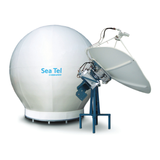
9797B-76 C/KU-BAND TX/RX ANTENNA
WARNING: RF RADIATION HAZARD
This stabilized antenna system is designed to be used with transmit/receive equipment
manufactured by others. Refer to the documentation supplied by the manufacturer which
will describe potential hazards, including exposure to RF radiation, associated with the
improper use of the transmit/receive equipment. Note that the transmit/receive
equipment will operate independently of the stabilized antenna system. Prior to work on
the stabilized antenna system, the power to the transmit/receive system must be locked
out and tagged.
When the transmit/receive system is in operation, no one should be allowed anywhere
within the radiated beam being emitted from the reflector.
The ultimate responsibility for safety rests with the facility operator and the
individuals who work on the system.
Sea Tel Inc doing business as Cobham SATCOM
FOR SEA TEL MODEL
Sea Tel Europe
Unit 1, Orion Industrial Centre
Wide Lane, Swaythling
Southampton, UK S0 18 2HJ
Tel: 44 (0)23 80 671155
Fax: 44 (0)23 80 671166
Email: seatel@cobham.com
Web:
Document. No. 131245 Revision A
www.cobham.com\seatel
Advertisement
Table of Contents
Troubleshooting

Subscribe to Our Youtube Channel
Related Manuals for Sea Tel 9797B-76


Summary of Contents for Sea Tel 9797B-76
- Page 1 Southampton, UK S0 18 2HJ Fax: (925) 798-7986 Tel: 44 (0)23 80 671155 Email: seatel@cobham.com Fax: 44 (0)23 80 671166 Web: : www.cobham.com\seatel Email: seatel@cobham.com Web: www.cobham.com\seatel Sea Tel Inc doing business as Cobham SATCOM January 13, 2010 Document. No. 131245 Revision A...
- Page 2 All Rights Reserved. The information contained in this document is proprietary to Sea Tel, Inc.. This document may not be reproduced or distributed in any form without prior consent of Sea Tel, Inc. The information in this document is subject to change without notice. Copyright © 2009 Sea Tel, Inc is doing business as Cobham SATCOM.
-
Page 5: Table Of Contents
Table of Contents 1. INTRODUCTION ......................................1-1 1.1.................................. 1-1 ENERAL YSTEM ESCRIPTION 1.2........................................... 1-1 URPOSE 1.3....................................1-1 YSTEM OMPONENTS 1.4................................1-2 ENERAL SCOPE OF THIS MANUAL 1.5................................. 1-2 UICK VERVIEW OF CONTENTS 2. OPERATION ........................................2-1 2.1. - Page 6 Table of Contents 4.3.2. Inspect / Inventory .................................. 4-2 4.3.3. Prepare ADE Mounting Location ............................4-2 4.3.4. Preparing BDE Location ................................. 4-3 4.3.5. Installing The System Cables ............................. 4-3 4.4. ADE ....................................4-3 SSEMBLING THE 4.4.1. 144” Radome, Baseframe and Antenna Pedestal System Assembly ............. 4-3 4.4.2.
- Page 7 00) ......................7-25 EDESTAL ONTROL ONFIGURATION 7.9.1. To configure the PCU; ................................7-25 7.9.2. MODEL CONFIGURATION NUMBERS ......................... 7-25 7.10. A ................................7-26 NTENNA TOWING ROCEDURE 8. 9797B-76 TECHNICAL SPECIFICATIONS ..........................8-1 8.1....................................8-1 NTENNA EFLECTOR 8.2......................................8-1 SSEMBLIES...
- Page 8 Table of Contents 8.2.1. C-Band Circular TXRX Feed Assembly ........................... 8-1 8.2.2. Ku- Band TXRX Feed Assembly ............................8-1 8.3. 9797B-76 RF E ..................................8-1 QUIPMENT 8.4. SMW Q LNB ....................................8-2 8.5. (PCU) ................................8-2 EDESTAL ONTROL 8.6. 400 MH &...
-
Page 9: Introduction
9797B-76 C/Ku-Band TXRX Introduction Introduction WARNING: RF Radiation Hazard - This stabilized antenna system is designed to be used with transmit/receive equipment manufactured by others. Refer to the documentation supplied by the manufacturer which will describe potential hazards, including exposure to RF radiation, associated with the improper use of the transmit/receive equipment. -
Page 10: General Scope Of This Manual
1.4. General scope of this manual This manual describes the Sea Tel Series 97 Antenna (also called the Above Decks Equipment), its’ operation and installation. Refer to the manual provided with your Antenna Control Unit for its’ installation and operating instructions. -
Page 11: System Power-Up
9797B-76 C/Ku-Band TXRX Operation Operation WARNING: RF Radiation Hazard - This stabilized antenna system is designed to be used with transmit/receive equipment manufactured by others. Refer to the documentation supplied by the manufacturer which will describe potential hazards, including exposure to RF radiation, associated with the improper use of the transmit/receive equipment. -
Page 12: Stabilized Pedestal Assembly Operation
Operation 9797B-76 C/Ku-Band TXRX 2.4. Stabilized Pedestal Assembly Operation Operation of the stabilized antenna Pedestal Control Unit (PCU) is accomplished remotely by the Antenna Control Unit (ACU). Refer to the Operation section of the Antenna Control Unit manual for more specific operation details. There are no other operating instructions applicable to the pedestal assembly by itself. -
Page 13: Rf Equipment
9797B-76 C/Ku-Band TXRX Operation 2.9. RF Equipment The RF Equipment is not operated or controlled by the antenna pedestal or Antenna Control Unit. Refer to the vendor supplied manuals for the RF Equipment provided with your system. 2.10. Radome Assembly Operation When operating the system it is necessary that the radome access hatch (and/or side door) be closed and secured in place at all times. - Page 14 Operation 9797B-76 C/Ku-Band TXRX This Page Intentionally Left Blank...
-
Page 15: Basic System Information
9797B-76 C/Ku-Band TXRX Basic System Information Basic System Information This section provides you with some additional information about the satellites you will be using, basics of your Series 97 antenna system and some of the other equipment within your system configuration. -
Page 16: Satellite Footprints
Basic System Information 9797B-76 C/Ku-Band TXRX satellite signal level required for your size of antenna (refer to the Specifications section of this manual) to provide suitable reception. This limits the number of satellites that can be used and the geographic areas where the ship can travel where the signal level is expected to be strong enough to continue providing uninterrupted reception. -
Page 17: Antenna Polarization
9797B-76 C/Ku-Band TXRX Basic System Information operations of the antenna. The actual elevation pointing angle to the satellite is determined by your latitude & longitude and the longitude of the satellite. In general terms the elevation angle will be low when you are at a high latitudes and will increase as you get closer to the equator. -
Page 18: Components Of The System Configuration
Basic System Information 9797B-76 C/Ku-Band TXRX 3.3. Components of the System Configuration Figure 3-2 Series 97 TXRX Simplified Block Diagram The following text provides a basic functional overview of the system components and component interconnection as referred to in the simplified block diagram for your Series 97 antenna. Also, refer to the appropriate page of the... -
Page 19: Antenna Ade Assembly
9797B-76 C/Ku-Band TXRX Basic System Information 3.3.1. Antenna ADE Assembly The Above Decks Equipment consists of an Antenna Pedestal inside a Radome assembly. The pedestal consists of a satellite antenna dish & feed with a linear, or a circular Low... -
Page 20: Positive Satellite Id
(proper option files) and the ACU/PCU (setup parameters) are actually compatible for the intended satellite(s). 3.5.2. Interface requirements: 3.5.2.1. Hardware Sea Tel Antenna Control Units Model DAC2202 or DAC2302. Any Satellite modem manufacturer that is compatible with OpenAMIP CAT5 Patch cable 3.5.2.2. Software Sea Tel model DAC2202: ACU software version 6.06 or greater... - Page 21 9797B-76 C/Ku-Band TXRX Basic System Information H f1 f2 Tracking Frequency: 2 Parameters: “H 14123.321 0.256” Center Frequency and Bandwidth in MHz B f1 f2 Down Conversion Offset: 2 parameters: “B 10750” LNB (Receive) Local Oscillator and BUC (TX) L.O.
- Page 22 Basic System Information 9797B-76 C/Ku-Band TXRX This Page Intentionally Left Blank...
-
Page 23: Installation
9797B-76 C/Ku-Band TXRX Installation Installation This section contains instructions for unpacking, final assembly and installation of the equipment. It is highly recommended that final assembly and installation of the Antenna system be performed by trained technicians. Read this complete section before starting. -
Page 24: Site Survey
Installation 9797B-76 C/Ku-Band TXRX WARNING: RF Radiation Hazard - This stabilized antenna system is designed to be used with transmit/receive equipment manufactured by others. Refer to the documentation supplied by the manufacturer which will describe potential hazards, including exposure to RF radiation, associated with the improper use of the transmit/receive equipment. -
Page 25: Preparing Bde Location
9797B-76 C/Ku-Band TXRX Installation 4.3.4. Preparing BDE Location Prepare the mounting location for the Below Decks Equipment. These equipments would normally be installed in a standard 19” equipment rack. Refer to the Antenna Control Unit manual for installation of the ACU and the Terminal Mounting Strip. -
Page 26: Preparing The Ade For Lift
Installation 9797B-76 C/Ku-Band TXRX Set the lower half of the radome assembly on the base pan aligning the painted numbers on the radome panels. Loosely attach the lower side panel assembly to the base frame using the hardware provided. Do NOT tighten the bolts at this time. Lift the lower side panel assembly wide enough to install a good bead of silicone caulk between it and the base pan, then firmly tighten all the bolts. -
Page 27: Install Antenna/Radome/Baseframe
Sea Tel recommends that separate, dedicated, AC Power be provided for the Marine Air Conditioner (Do NOT combine with the AC Power provided for the Antenna Pedestal and RF Equipment). This AC Power cable is routed into the Marine Air Conditioner and terminated to the AC terminals inside. -
Page 28: Balance Antenna Pedestal
Installation 9797B-76 C/Ku-Band TXRX 4.8.4. Balance Antenna Pedestal Assure that the antenna assembly is balanced front to back, top to bottom and side to side by observing that it remains stationary when positioned in any orientation. Refer to the Maintenance section for complete information on balancing the antenna. -
Page 29: Setup
9797B-76 C/Ku-Band TXRX Setup Setup Below are basic steps to guide you in setting up the ACU for your specific antenna pedestal. Assure that the Antenna Pedestal (ADE) has been properly installed before proceeding. Refer to the Setup section of you ACU manual for additional parameter setting details. -
Page 30: Sat Skew Setting
Setup 9797B-76 C/Ku-Band TXRX has acquired (and peaks up on) the satellite that you targeted. Allow several minutes for the antenna to “peak” on the signal, and then record the Azimuth and Elevation positions while peaked on satellite (these are the Peak positions). -
Page 31: Calibrating Relative Antenna Position (Home Flag Offset)
9797B-76 C/Ku-Band TXRX Setup Press the RIGHT key again, make the next change as directed and hit ENTER to carry out the adjustment. Repeat this process of making small adjustments until the technician confirms that cross-pol isolation is optimized. Save your new SAT SKEW value. -
Page 32: To Enter The Hfo Value
Setup 9797B-76 C/Ku-Band TXRX If the antenna stopped before it got to the bow-line; When you initially target a satellite, the antenna will also stop prior to the satellite position, so you that will have to drive the Azimuth of the antenna UP to actually find the satellite. -
Page 33: Radiation Hazard And Blockage Mapping (Az Limit Parameters)
9797B-76 C/Ku-Band TXRX Setup increment/decrement the underscored value. When you have finished editing the display value, press ENTER to send the HFO value command to the PCU (but it is not save yet). If you want to find out what the current HFO value is key in N6999 and hit ENTER. -
Page 34: Fixed Frequency Low Noise Block Converter Operation/Selection
Setup 9797B-76 C/Ku-Band TXRX 5.7. Fixed Frequency Low Noise Block Converter Operation/Selection: When you have your C-Band RF equipment installed, or Ku-Band fixed frequency LNB, you must set the “TrackDisp” parameter to 0000. Band selection controls the local logic output state of SW1 output terminal on the Terminal Mounting Strip PCB AND remote 22KHz tone, 13/18 VDC LNB power and relays or switches on the antenna pedestal. -
Page 35: Acu Factory Default Parameter Settings - Series 97B & 00B Antennas
9797B-76 C/Ku-Band TXRX Setup 5.9. ACU Factory Default Parameter Settings – Series 97B & 00B Antennas The following table shows the factory default parameters for the ACU interfaced to a Series 97B/00B Antenna. You may need to optimize some of these parameters. Refer to the individual parameter setting information in the Setup section of your ACU manual. - Page 36 Setup 9797B-76 C/Ku-Band TXRX This Page Intentionally Left Blank...
-
Page 37: Functional Testing
Press RESET on the ACU front panel. Verify the display shows "SEA TEL INC - MASTER" and the ACU software version number. Wait 10 seconds for the display to change to "SEA TEL INC - REMOTE" and the PCU software version number. If the display shows "REMOTE INITIALIZING” wait for approximately 2 minutes for the antenna to complete initialization and report the Antenna Model and PCU software version. -
Page 38: Four Quadrant Test Tracking
Functional Testing 9797B-76 C/Ku-Band TXRX RIGHT arrow key repeatedly and verify that the antenna physically moves up (CW) in Press the Azimuth and that the display accurately reflects that movement. Press the LEFT arrow key repeatedly and verify that the antenna physically moves down (CCW) in Azimuth and that the display accurately reflects that movement. -
Page 39: Maintenance And Troubleshooting
7.1. Warranty Information Sea Tel Inc. supports its Series 97, 00, 06 and 07 systems with a ONE YEAR warranty on parts and labor. What’s Covered by the Limited Warranty? The Sea Tel Limited Warranty is applicable for parts and labor coverage to the complete antenna system, including all above-decks equipment (radome, pedestal, antenna, motors, electronics, wiring, etc.) and the Antenna Control Unit... -
Page 40: Check Acu Parameters
Maintenance and Troubleshooting 9797B-76 C/Ku-Band TXRX 7.2.1. Check ACU Parameters Assure that the parameters are set correctly (you may wish to record them in the Factory Default Settings, in section 5 of this manual). 7.2.2. Latitude/Longitude Auto-Update check Refer to the Latitude & Longitude Update check procedure in the Functional Testing section of this manual. -
Page 41: Observe Antenna Initialization
9797B-76 C/Ku-Band TXRX Maintenance and Troubleshooting 7.2.9. Observe Antenna Initialization Observe the Antenna Initialization as described in the Troubleshooting section below. 7.3. 400MHz Modem Configuration The 400MHz FSK modem PCB has a jumper block (located component side of PCB) that is used to configure it for Above Decks or Below Decks operation as well as to configure its’... -
Page 42: Mh Zled Indicators
Maintenance and Troubleshooting 9797B-76 C/Ku-Band TXRX Below 2 Wire RS485 Decks (Half Duplex) 9-10 7.4. 400 MHz LED indicators For diagnostic purposes, the 400MHz FSK Modem Assemblies have an LED Indicator (located to the on the bottom left hand side of the Enclosure for BDE modems and directly underneath the Rotary Joint port on the 09 Series PCU). By observing the amount of amber colored flashes during power up, the modems configuration may be established. -
Page 43: Radio M&C
9797B-76 C/Ku-Band TXRX Maintenance and Troubleshooting 7.5.2. Radio M&C The RS-232, RS-422, or RS-485 (depending on configuration) Radio M&C signals pass from the BDE computer through the RF M&C port of the base modem and are modulated and demodulated. These M&C signals are diplexed with the Pedestal M&C signals before passing through to the above decks modem. -
Page 44: Troubleshooting 400Mhz Modem Communication Faults
Maintenance and Troubleshooting 9797B-76 C/Ku-Band TXRX 7.6. Troubleshooting 400MHz Modem Communication Faults 7.6.1. 400MHz Modem Queries: The 400MHz modem assemblies facilitates the use of line-based commands via the ACU’s front panel, its’ internal HTML page, or using remote diagnostic software such as DacRemP or ProgTerm. The use of these commands will aid in troubleshooting communication failures between the above decks and below decks modems. - Page 45 9797B-76 C/Ku-Band TXRX Maintenance and Troubleshooting 7.6.2.1. Using the ACU Front Panel Using the ACU’s Front Panel, navigate through the Setup menu to access the Remote Command Sub-Menu. Enter in the desired Modem Query then press the ENTER key. Observe and/or Record the displayed response.
-
Page 46: Isolating A 400 Mhz Modem Fault Procedure
Maintenance and Troubleshooting 9797B-76 C/Ku-Band TXRX Observe and/or Record the displayed response. Repeat as required until all desired modem queries are noted. 7.6.2.4. Using ProgTerm Open up ProgTerm and select the Tools Menu. Select “Modem Tools”. Select the desired modem location. - Page 47 9797B-76 C/Ku-Band TXRX Maintenance and Troubleshooting Serial Loopback Connector Build a Loop Back Test Adapter by Shorting Pin 1 to Pin 8 and Shorting Pin 2 to Pin 3 on a female DB9(S) connector. Spectrum Analyzer Capable of handling 100kHz up to 3Ghz & up to 48VDC SMA “T”...
- Page 48 Maintenance and Troubleshooting 9797B-76 C/Ku-Band TXRX Verify BDE modem and ADE modem are properly configured (jumper block settings). ACU to BDE modem interface cable failure Verify harness continuity. Repair or replace as required ACU Antenna Port Failure Install an RS232 Loopback connector** on Antenna Port of the ACU. Enter an “n0999”...
-
Page 49: Troubleshooting
9797B-76 C/Ku-Band TXRX Maintenance and Troubleshooting 7.6.3.1.8. BDE Receive or ADE Transmit (RF M&C): BDE Modem Rx Port Failure (Not receiving at 460.0MHz) or ADE Modem Tx Port Failure (Not transmitting at 460.0MHz) Install Spectrum Analyzer in line with the Rx IF coax path. -
Page 50: Troubleshooting Using Dacremp
7.7.3. Troubleshooting using DacRemP While troubleshooting a Sea Tel 3-Axis Antenna System, you must classify the fault you are dealing with as a failure within one of 3 major system functions, Targeting, Stabilization, and Tracking. Should there be a failure with any one of these functions, your system will not operate properly. A few simple checks may help determine which fault (if any) that you are dealing with. -
Page 51: Antenna Loop Error Monitoring
9797B-76 C/Ku-Band TXRX Maintenance and Troubleshooting Level cage alignment Verification (sensor DISPV (Ref) Targeting alignment) Stabilization Rate Sensor Output Verification DISPW (Rate) Stabilization Level and CL fine balance Verification DISPTC (Drive) Stabilization AZ Friction Torque Test DISPTC (Drive) Stabilization DishScan Drive/Phase... -
Page 52: Reference Sensor Monitoring
Maintenance and Troubleshooting 9797B-76 C/Ku-Band TXRX • Cross-Level Axis physically moved CCW (down to the left.) and then CW (up to the right.) Elevation Axis physically moved CW. (reflector slightly pushed up) and then physically moved CCW. (reflector slightly pushed down.) At the end of chart recording shows •... - Page 53 9797B-76 C/Ku-Band TXRX Maintenance and Troubleshooting • The normal trace display for the Tilt Sensor, after performing remote tilt calibration, will be ± 4 divisions from the red reference line. Any trace line average plotted above this is of concern and troubleshooting required.
-
Page 54: Open Loop Rate Sensor Monitoring
Maintenance and Troubleshooting 9797B-76 C/Ku-Band TXRX 7.7.6. Open Loop Rate Sensor Monitoring The DacRemP DISPW graph chart provides a means for monitoring the output of the 3 solid state rate sensors (located inside the Level Cage Assembly) for diagnostic purposes. The rate sensors are the primary inputs to the PCU for stabilization. -
Page 55: Fine Balance And Monitoring Motor Drive Torque
9797B-76 C/Ku-Band TXRX Maintenance and Troubleshooting 7.7.7. Fine Balance and Monitoring Motor Drive Torque The DacRemP DISPTC graph chart provides a means for monitoring torque commands required for each motor for diagnostic purposes and verifying antenna balance. By observing each trace, the required drive of the antenna via the motor driver PCB may be established. -
Page 56: Open Loop Motor Test
Maintenance and Troubleshooting 9797B-76 C/Ku-Band TXRX • The Level display should decrease (plots below red line) as the antenna requires drive forward (Up in elevation) and increase (plots above red line) as the antenna requires drive back (Down in elevation). -
Page 57: To Disable/Enable Dishscan
9797B-76 C/Ku-Band TXRX Maintenance and Troubleshooting • To drive the Level motor, key in ^2064, ^2128 or ^2192 and press ENTER to drive the level axis FORWARD, OFF or BACKWARD respectively. • To drive the Azimuth motor, key in ^3064, ^3128 or ^3192 and press ENTER to drive the azimuth axis CW, OFF or CCW. - Page 58 Maintenance and Troubleshooting 9797B-76 C/Ku-Band TXRX Select the “Comm Diagnostics” window under to the Tools submenu or Press “CTRL + C” Left mouse click on the icon. Right mouse click on the icon. This will display a list box with...
- Page 59 9797B-76 C/Ku-Band TXRX Maintenance and Troubleshooting State Description PCU Status (Word 1) Slow Scan Indicates antenna is in a specialized mode, Slow Scan, which is required when ever a test requires driving the antenna >5°/sec Sat Reference Indicates that satellite reference mode is enabled.
-
Page 60: Remote Gps Lat/Lon Position
Maintenance and Troubleshooting 9797B-76 C/Ku-Band TXRX 7.7.12. Remote GPS LAT/LON Position: The above decks equipment has an integrated on board Furuno GPS antenna system. The Latitude and Longitude position information provided are utilized to calculate the Azimuth, Elevation, Cross-level and Polarity pointing angles of the desired satellite. -
Page 61: Maintenance
Furuno default value is in Japan at 34.4N 135.2E (@3444,N,13521,E,,_). After acquiring a good fix at Sea Tel the string is @3800,N,12202,W,A^ for our 38N 122W Latitude and Longitude position. The status character tells you the status of the GPS. -
Page 62: To Adjust Tilt
Maintenance and Troubleshooting 9797B-76 C/Ku-Band TXRX one location on the equipment frame to the same location on the opposite side of the equipment frame (ie from the top left of the reflector mounting frame to the top right of the reflector mounting frame). -
Page 63: Pedestal Control Unit Configuration ( Xx 97B
9797B-76 C/Ku-Band TXRX Maintenance and Troubleshooting 7.9. Pedestal Control Unit Configuration (xx97B & xx00) The PCU is designed to be used with a variety of antenna pedestal configurations. The configuration information that is unique to each pedestal type is stored in a Non Volatile Random Access Memory (NVRAM) in the PCU enclosure. If the PCU is replaced or the NVRAM in the PCU should become corrupt, the PCU must be re-configured to operate with the pedestal it is installed on. -
Page 64: 7.10. Antenna Stowing Procedure
The normal operating condition for the Sea Tel Antenna system is to remain powered up at all times. This ensures that the antenna remains actively stabilized to prevent physical damage to the antenna pedestal and reduce condensation and moisture in the radome to prevent corrosion. - Page 65 9797B-76 C/Ku-Band TXRX Maintenance and Troubleshooting Hook the other end hook of the nylon strap to the pedestal- mounting frame as shown in Figure 3. Use the ratchet of the strap to tighten nylon straps. As the straps are tightened, observe the vertical isolation canister assembly as shown in Figure 4.
- Page 66 Maintenance and Troubleshooting 9797B-76 C/Ku-Band TXRX This Page Intentionally Left Blank 7-28...
-
Page 67: 76 Technical Specifications
9797B-76 C/Ku-Band TXRX 9797B-76 Technical Specifications 9797B-76 Technical Specifications The technical specifications for your Series 97B Above Decks Equipment subsystems are listed below: Refer to your ACU manual for its’ Specifications. 8.1. Antenna Reflector Type Honeycomb Fiberglass Parabola Diameter (D) 2.4 Meter Modified Offset... -
Page 68: Smw Quad Band Lnb
9797B-76 Technical Specifications 9797B-76 C/Ku-Band TXRX 8.4. SMW Quad Band LNB Band 1 Voltage Required 13 VDC Input RF Frequency 10.95-11.70 GHz Local Oscillator Frequency 10.00 GHz Output IF Frequency 950 to 1700 MHz Band 2 Voltage & Tone Required... -
Page 69: Mh Z Base & Pedestal Unlimited Azimuth Modems (3 Channel )
9797B-76 C/Ku-Band TXRX 9797B-76 Technical Specifications 8.6. 400 MHz Base & Pedestal Unlimited Azimuth Modems (3 Channel) Combined Signals (-1,-2) Pass-Thru 950-3200 MHz RX IF, Injected 22Khz Tone DC LNB Voltage Select 400 MHz Pedestal M&C Connectors: RX IF L-Band... -
Page 70: Stabilized Antenna Pedestal Assembly
9797B-76 Technical Specifications 9797B-76 C/Ku-Band TXRX 8.7. Stabilized Antenna Pedestal Assembly Type: Three-axis (Level, Cross Level and Azimuth) Stabilization: Torque Mode Servo Stab Accuracy: 0.2 degrees MAX, 0.1 degrees RMS in presence of specified ship motions (see below). LV, CL, AZ motors: Size 34 Brushless DC Servo. -
Page 71: 144" Radome Assembly
Withstand relative average winds up to 100 MPH from any direction. Ingress Protection Rating All Sea Tel radomes have an IP rating of 56 NOTE: Radome panels can absorb up to 50% moisture by weight. Soaked panels will also have higher attenuation. -
Page 72: 8.10. Cables
Antenna Transmit & Receive IF Coax Cables (Customer Furnished) Due to the dB losses across the length of the RF coaxes at L-Band, Sea Tel recommends the following 50 ohm coax cable types (and their equivalent conductor size) for our standard pedestal installations:... -
Page 73: Gyro Compass Interface Cable (Customer Furnished)
9797B-76 C/Ku-Band TXRX 9797B-76 Technical Specifications 8.10.6. Gyro Compass Interface Cable (Customer Furnished) Type: Multi-conductor, Shielded Number of wires 4 Conductors for Step-By-Step Gyro, 5 Conductors for Synchro Wire Gauge: see Multi-conductor Cables spec above Insulation: 600 VAC... - Page 74 9797B-76 Technical Specifications 9797B-76 C/Ku-Band TXRX This Page Intentionally Left Blank...
-
Page 75: Drawings
9.1. 9797B-69 Model Specific Drawings Drawing Title 130166-104_B System, Model 9797B-76 1130162_C System Block Diagram – Model 9797B-76 130167-1_C General Assembly – Model 9797B-76 9-12 127641_B Antenna System Schematic – Model 9797B-76 9-14 127991-1_C1... - Page 76 Drawings 9797B-76 C/Ku-Band TXRX This Page Intentionally Left Blank...
- Page 77 DAC-2202, SCPC RCVR, 9 WIRE IF (NOT SHOWN) 1 EA 129615-1 BELOW DECK KIT, L-BAND, 400MHZ, RS-23 (NOT SHOWN) 1 EA 130857-23 CUSTOMER DOC PACKET, 9797B-76, 400MHZ (NOT SHOWN) 1 EA 122539-1 SHIP STOWAGE KIT, XX97 (NOT SHOWN) 1 EA 114569 D BALANCE WEIGHT KIT...
- Page 78 X.X = .050 DRAWN DATE: 5-19-09 X.XX = .020 Tel. 925-798-7979 Fax. 925-798-7986 X.XXX = .005 APPROVED BY: TITLE: ANGLES: .5 SYSTEM, 9797B-76 INTERPRET TOLERANCING PER ASME Y14.5M - 1994 MATERIAL: APPROVED DATE: FINISH: SIZE SCALE: DRAWING NUMBER 1:20 130166 9797B-76...
- Page 79 G1 CABLE ASS'Y, SMA(M)-N(M), 15 FT. 1 EA 114973-120 E1 CABLE ASS'Y, N(M)-N(M), 120 IN. 1 EA 114972-9 N CABLE ASS'Y, SMA(M) - SMA(M), 6 IN SYSTEM BLOCK DIAGRAM, 9797B-76, C-BAND PROD FAMILY EFF. DATE DRAWING SHT 1 OF 1/11/2010...
- Page 80 B1 CABLE ASS'Y, CAT5 JUMPER, 10 FT. 1 EA 126877 B1 HARNESS ASS'Y, COMTECH MODEM COMTECH INTERFAC 1 EA 119478-5 D CABLE ASS'Y, RJ-45 SERIAL, 60 IN. I DIRECT SYSTEM BLOCK DIAGRAM, 9797B-76, C-BAND PROD FAMILY EFF. DATE DRAWING SHT 2 OF 1/11/2010 NUMBER 130162-1...
- Page 81 CABLE ASS'Y, RS232, 9-WIRE, STRAIGHT, 1 EA 115492-1 C1 ADAPTER, N(F)-SMA(F), W/FLANGE 1 EA 110567-19 ADAPTER, N(F)-N(F), STRAIGHT, FLANGE 1 EA 111003-18 ADAPTER, BNC(F)-F(M) SYSTEM BLOCK DIAGRAM, 9797B-76, C-BAND PROD FAMILY EFF. DATE DRAWING SHT 3 OF 1/11/2010 NUMBER 130162-1...
- Page 82 G1 CABLE ASS'Y, SMA(M)-N(M), 15 FT. 1 EA 114973-72 E1 CABLE ASS'Y, N(M)-N(M), 72 IN. 1 EA 114972-9 N CABLE ASS'Y, SMA(M) - SMA(M), 6 IN SYSTEM BLOCK DIAGRAM, 9797B-76, KU-BAND PROD FAMILY EFF. DATE DRAWING SHT 1 OF 1/11/2010...
- Page 83 D CABLE ASS'Y, RJ-45 SERIAL, 60 IN. I DIRECT 1 EA 126877 B1 HARNESS ASS'Y, COMTECH MODEM COMTECH INTERFAC 1 EA 120643-6 CABLE ASS'Y, RS232, 9-WIRE, STRAIGHT, SYSTEM BLOCK DIAGRAM, 9797B-76, KU-BAND PROD FAMILY EFF. DATE DRAWING SHT 2 OF 1/11/2010 NUMBER 130162-2...
- Page 84 PART NO REV DESCRIPTION REFERENCE DESIGNATOR 1 EA 115492-1 C1 ADAPTER, N(F)-SMA(F), W/FLANGE 1 EA 110567-19 ADAPTER, N(F)-N(F), STRAIGHT, FLANGE 1 EA 111003-18 ADAPTER, BNC(F)-F(M) SYSTEM BLOCK DIAGRAM, 9797B-76, KU-BAND PROD FAMILY EFF. DATE DRAWING SHT 3 OF 1/11/2010 NUMBER 130162-2...
- Page 86 1 EA 127991-1 C1 ANTENNA ASS'Y, 2.4M OFFSET, 9797B 1 EA 130171-1 WAVEGUIDE RUN ASSY, 9797B-76 1 EA 130218-1 BALANCE WEIGHT KIT, EL & CL, 9797B-76 1 EA 121655-1 LABELS INSTALLATION 1 EA 123530-5 GROUND BONDING KIT, DUAL RF (NOT SHOWN) 1 EA 111079-15 G1 CABLE ASS'Y, SMA(M)-N(M), 15 FT.
- Page 87 INTERPRET TOLERANCING PER ASME Y14.5M - 1994 KU-BAND CONFIGURATION MATERIAL: APPROVED DATE: 9797B-76 NOTES: UNLESS OTHERWISE SPECIFIED INSTALL GROUND BONDING KIT PER FINISH: SIZE SCALE: DRAWING NUMBER SEA TEL SPEC 127315. 1:15 130167 9797B-76 3rd ANGLE 1 OF 1 FIRST USED: SHEET NUMBER PROJECTION...
- Page 89 SINGLE LEVEL MFG BILL OF MATERIAL FIND PART NO DESCRIPTION REFERENCE DESIGNATOR 116803 REFLECTOR, OFFSET, 2.4M 120292 FEED STRUT, TOP 120293 FEED STRUT, LEFT 120294 FEED STRUT, RIGHT 123208 SCALAR PLATE ASS'Y, DISHSCAN 128430-1 HARDWARE KIT, INSTALL OFFSET ANTEN 118294-6 HARDWARE KIT, WR-75, UG FLANGE, M4 118294-4 HARDWARE KIT, WR-229, CPR FLANGE...
- Page 92 NUT, HEX, 10-32, S.S. 6 EA 114586-545 SCREW, HEX HD, 1/4-20 x 2-1/2, S.S. 12 EA 114580-029 WASHER, FLAT, 1/4, S.S. 6 EA 114583-029 NUT, HEX, 1/4-20, S.S. WAVEGUIDE RUN ASSY, 9797B-76 PROD FAMILY EFF. DATE DRAWING SHT 1 OF COMMON 7/1/2009...
- Page 93 X.XX = .020 Tel. 925-798-7979 Fax. 925-798-7986 X.XXX = .005 APPROVED BY: TITLE: ANGLES: .5 WAVEGUIDE RUN ASS'Y, INTERPRET TOLERANCING PER ASME Y14.5M - 1994 MATERIAL: APPROVED DATE: 9797B-76 FINISH: SIZE SCALE: DRAWING NUMBER 1:10 130171 KU BAND CONFIGURATION 9797B-76 3rd ANGLE...
- Page 94 68 68 58 58 SIZE SCALE: DRAWING NUMBER C BAND CONFIGURATION 1:10 130171 2 OF 2 SHEET NUMBER...
- Page 95 SINGLE LEVEL MFG BILL OF MATERIAL FIND QTY PART NO REV DESCRIPTION REFERENCE DESIGNATOR 1 EA 123290 THROAT ASS'Y, C-BAND, LINEAR, DISHSC 1 EA 116922 B1 OMT-46, C-BAND 1 EA 117543 STOP, POLANG 1 EA 115509 D WAVEGUIDE, WR-137, ROTARY JOINT, L-S 1 EA 117218-2 GASKET, WR-137, (CPRG FULL) 1 EA 118294-3...
- Page 97 SINGLE LEVEL MFG BILL OF MATERIAL FIND PART NO DESCRIPTION REFERENCE DESIGNATOR 126368-1 BRACKET, FEED COUNTERWEIGHT, WR-7 123660-1 SCALAR PLATE, KU-BAND 118828 OMT, KU-BAND 128388 FILTER, RECEIVE BANDPASS, KU-BAND 108519-4 WEIGHT, TRIM 7.0 OZ, BLUE 108517-2 WEIGHT, TRIM 1.0 OZ 123282 FEED SPACER, KU-BAND, DISHSCAN 116225...
- Page 98 SINGLE LEVEL MFG BILL OF MATERIAL FIND PART NO DESCRIPTION REFERENCE DESIGNATOR 114580-029 WASHER, FLAT, 1/4, S.S. 114576-144 SCREW, FLAT HD, PHIL, 6-32 x 1/4, S.S. 117542 GEAR, POLANG SPINDLE 114771-33 SNAP RING, EXTERNAL, 2.500 SHAFT, LT 119499 RING, RETAINER, BEARING 115439-2 BEARING, X-STYLE, 2.500 ID, 3.000 OD, SE 114593-214...
- Page 100 SINGLE LEVEL MFG BILL OF MATERIAL FIND PART NO DESCRIPTION REFERENCE DESIGNATOR NOT SHOWN 117762-1 SILICONE ADHESIVE, WHT RTV 122, 10.1 NOT SHOWN 110327 HARDWARE KIT, 144 INCH RADOME 109119-17 RADOME FAB ASS'Y, 144 INCH, WHITE/SID 124903-1 STRAIN RELIEF ASS'Y INCLUDED IN HARDWARE KIT 114586-538 SCREW, HEX HD, 1/4-20 x 1, S.S.
- Page 102 SINGLE LEVEL MFG BILL OF MATERIAL FIND PART NO DESCRIPTION REFERENCE DESIGNATOR 123724-1 RADOME BASE FRAME ASS'Y, 75 IN, STEE 124459-1 RADOME BASE PAN FAB, WHITE, W/INTER 123728-2 RADOME PAN ACCESS ASS'Y, WHITE 122508 A/C INSTALL ASS'Y, INTERNAL 114622-544 SCREW, HEX HD, FULL THRD, 1/4-20 x 1-1/ 114622-724 SCREW, HEX HD, FULL THRD, 1/2-13 x 3 IN 114622-628...
- Page 103 NOTES: (UNLESS OTHERWISE SPECIFIED) 1-14-05 RELEASED TO PRODUCTION NONE 04-13-05 -9 ADDED 1. APPLY ADHESIVE PER SEA TEL SPEC. 121730. NONE 04-29-05 -9 BASE FRAME WS STL. LG. FOOT, BASE PAN WS P/N 123726-2 4888 05-31-05 FOR -5, -6, -8, -9 BASE PAN WAS P/N 123726-1.
- Page 104 REVISION HISTORY REV ECO# DATE DESCRIPTION 4609 10-05-04 RELEASED TO PRODUCTION 4858 5-5-05 ADD REFERENCE 121113 3-2-06 CHANGED TO TABLE FORMAT V.S. CONTROL PANEL 1-9-07 CREATED CAD OUTLINE DRAWING 17.85 12.80 AIR FLOW 2.53 31.88 33.00 18 MAX 30.00 1.50 15.25 15.9 INLET...
- Page 105 SINGLE LEVEL MFG BILL OF MATERIAL FIND QTY PART NO REV DESCRIPTION REFERENCE DESIGNATOR 1 EA 116941 STREET ELBOW, 1/2 INCH 1 EA 116938 FLEX HOSE, 1/2 INCH 2 EA 124903-1 B1 STRAIN RELIEF ASS'Y 1 EA 121008-72 D2 CABLE ASS'Y, AC INPUT, 72 IN. (SPADE (NOT SHOWN) 4 EA 120470 ISOLATORS, BUMPER...
- Page 107 DETAIL A SCALE: NONE FLUSH MOUNT RADOME MOUNTING HOLE PATTERN MOUNTING HOLE PATTERN W/LEGS SEE DETAIL A...
- Page 108 ITEM DESCRIPTION WEIGHT (Lb.) ** NET* ITEM DESCRIPTION WEIGHT (LB.) ITEM DESCRIPTION WEIGHT (Lb.) ***...
- Page 109 SINGLE LEVEL MFG BILL OF MATERIAL FIND QTY PART NO REV DESCRIPTION REFERENCE DESIGNATOR 1 EA 127513-1 PCU ENCLOSURE ASS'Y, XX97B, STD 1 EA 122208-1 N LEVEL CAGE ASS'Y, SIDE EXIT, 080 P., 1 EA 115425-2 J3 POT ASS'Y (ELEX.), POLANG 1 EA 114590-144 SCREW, SOCKET SET-CUP, 6-32 x 1/4, S.
- Page 110 SINGLE LEVEL MFG BILL OF MATERIAL FIND QTY PART NO REV DESCRIPTION REFERENCE DESIGNATOR 1 EA 128878-1 SPARE PARTS KIT, XX97B, TX/RX, STANDA 1 EA 116024-3 SHIELDED POLANG RELAY ASS'Y 1 EA 125974-1 MOTOR, SIZE 34, BLDC W/ BRAKE, 15-PIN 1 EA 127825-1 TIMING PULLEY, 15T 1 EA 115352-473...
- Page 111 SINGLE LEVEL MFG BILL OF MATERIAL FIND QTY PART NO REV DESCRIPTION REFERENCE DESIGNATOR 1 EA 128878-2 SPARE PARTS KIT, XX97B, TX/RX, PREMIU 1 EA 116034 HOME SWITCH ASS'Y, SHIELDED 1 EA 116466 D ROTARY JOINT, 4.5 GHz, DUAL COAX. 1 EA 121250-2 C3 POWER RING ASS'Y, 22 IN, 96 IN.
- Page 113 SINGLE LEVEL MFG BILL OF MATERIAL FIND PART NO DESCRIPTION REFERENCE DESIGNATOR 112657 MACHINING, TERMINAL MOUNTING STRIP 126865-2 PCB ASS'Y, TERMINAL MOUNTING STRIP, 112936-36 CABLE ASS'Y, D-SDB, 25 PIN, 36 IN 116669-36 CABLE ASS'Y, D-SUB, 9-PIN, 36 IN. 121228-3072 STANDOFF, HEX, F/F, 6-32 X .25 OD X .50, 114588-146 SCREW, PAN HD, PHIL, 6-32 x 3/8, S.S.
- Page 115 SINGLE LEVEL MFG BILL OF MATERIAL FIND PART NO DESCRIPTION REFERENCE DESIGNATOR 116880 PANEL MACHINING, RACK, BASE MUX 117168-2 MODEM ASS'Y, BASE, 3-CH. 75 OHM 117611-4 MODEM ASS'Y, BASE, 3 CH. -200, 50 OHM 116388 BRACKET, CONNECTOR 115492-1 ADAPTER, N(F)-SMA(F), W/FLANGE 110567-19 ADAPTER, N(F)-N(F), STRAIGHT, FLANGE 114972-9...
Need help?
Do you have a question about the 9797B-76 and is the answer not in the manual?
Questions and answers