Table of Contents
Advertisement
Sea Tel, Inc.
4030 Nelson Avenue
Concord, CA 94520
Tel: (925) 798-7979
Fax: (925) 798-7986
Web: :
www.cobham.com\seatel
March 7, 2011
INSTALLATION AND OPERATION MANUAL
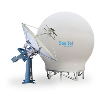
9497B-21 DUAL C/QUAD KU-BAND TVRO ANTENNA
Sea Tel Inc doing business as Cobham SATCOM
FOR SEA TEL MODEL
Sea Tel Europe
Unit 1, Orion Industrial Centre
Wide Lane, Swaythling
Southampton, UK S0 18 2HJ
Tel: 44 (0)23 80 671155
Fax: 44 (0)23 80 671166
Web:
Document. No. 132642 Revision A1
www.cobham.com\seatel
Advertisement
Table of Contents
Troubleshooting

Subscribe to Our Youtube Channel
Related Manuals for Sea Tel 9497B-21


Summary of Contents for Sea Tel 9497B-21
- Page 1 Tel: (925) 798-7979 Southampton, UK S0 18 2HJ Fax: (925) 798-7986 Tel: 44 (0)23 80 671155 Web: : www.cobham.com\seatel Fax: 44 (0)23 80 671166 Web: www.cobham.com\seatel Sea Tel Inc doing business as Cobham SATCOM March 7, 2011 Document. No. 132642 Revision A1...
- Page 2 All Rights Reserved. The information contained in this document is proprietary to Sea Tel, Inc.. This document may not be reproduced or distributed in any form without prior consent of Sea Tel, Inc. The information in this document is subject to change without notice. Copyright © 2010 Sea Tel, Inc is doing business as Cobham SATCOM.
- Page 4 Revision History ECO# Date Description August 17, 2010 Initial Production Release...
-
Page 5: Table Of Contents
Table of Contents INTRODUCTION ......................................1-1 1.1.................................. 1-1 ENERAL ESCRIPTION OF SYSTEM 1.2........................................... 1-1 URPOSE 1.3......................................1-1 YSTEM OMPONENTS 1.4..................................1-2 ENERAL SCOPE OF THIS MANUAL 1.5..................................1-2 UICK VERVIEW OF CONTENTS OPERATION ........................................2-1 2.1. - Page 6 Table of Contents 4.3.4. Preparing BDE Location ................................4-2 4.3.5. Installing The System Cables ..............................4-3 4.4................................. 4-3 REPARING NSTALLATION 4.4.1. Unpack Shipping Crates ................................4-3 4.4.2. Inspect / Inventory ..................................4-3 4.4.3. Prepare ADE Mounting Location ............................4-3 4.4.4.
- Page 7 ONFIGURATION 7.9.1. To configure the PCU; ................................7-25 7.9.2. MODEL CONFIGURATION NUMBERS ..........................7-25 7.10. A .................................. 7-26 NTENNA TOWING ROCEDURE 9497B-21 TECHNICAL SPECIFICATIONS ..........................8-1 8.1. 9497 A ..................................... 8-1 NTENNA EFLECTOR 8.2........................................8-1 SSEMBLIES 8.2.1. TVRO-21 Dual C-Band / Quad Ku-Band Feed Assembly ..................8-1 8.3.
- Page 8 8.8.3. AC Power Cable (Pedestal & Rf Equipment) ........................8-4 8.8.4. Gyro Compass Interface Cable (Customer Furnished) .................... 8-5 8.8.5. Fiber Optic Transmitter (CFE Optional) ..........................8-5 MODEL 9497B-21 DRAWINGS ................................9-1 9.1. 9497B-21 S ..............................9-1 ODEL PECIFIC RAWINGS 9.2.
-
Page 9: Introduction
9497B-21 C/Ku-Band TVRO Introduction Introduction 1.1. General Description of system Your Series 00 system is a fully stabilized antenna that has been designed and manufactured so as to be inherently reliable, easy to maintain, and simple to operate. Except for start-ups, or when changing to operate with different transponders or satellites, the equipment essentially permits unattended operation. -
Page 10: General Scope Of This Manual
1.4. General scope of this manual This manual describes the Sea Tel Antenna (also called the Above Decks Equipment), its’ operation and installation. Refer to the manual provided with your Antenna Control Unit for its’ installation and operating instructions. 1.5. -
Page 11: Operation
9497B-21 C/Ku-Band TVRO Operation Operation 2.1. System Power-up Turn the Power switch on the louvered panel of the antenna pedestal ON. This will energize the antenna pedestal and the associated RF equipment. Turn the Power switch on rear panel of the Antenna Control Unit (ACU) ON. -
Page 12: Low Noise Block Converter Operation
Operation 9497B-21 C/Ku-Band TVRO be operated manually from the ACU for diagnostic or alignment purposes. Refer to the Antenna Control Unit manual for more operation information. 2.7. Low Noise Block Converter Operation There are no operating instructions or controls applicable to the LNB. This unit is energized whenever the matrix switch and satellite receiver(s) have AC power connected to them. -
Page 13: Basic System Information
9497B-21 C/Ku-Band TVRO Basic System Information Basic System Information This section provides you with some additional information about the satellites you will be using, basics of your Series antenna system and some of the other equipment within your system configuration. -
Page 14: Satellite Footprints
Basic System Information 9497B-21 C/Ku-Band TVRO satellite signal level required for your size of antenna (refer to the Specifications section of this manual) to provide suitable reception. This limits the number of satellites that can be used and the geographic areas where the ship can travel where the signal level is expected to be strong enough to continue providing uninterrupted reception. -
Page 15: Feed Assembly
9497B-21 C/Ku-Band TVRO Basic System Information operations of the antenna. The actual elevation pointing angle to the satellite is determined by your latitude & longitude and the longitude of the satellite. In general terms the elevation angle will be low when you are at a high latitudes and will increase as you get closer to the equator. -
Page 16: Components Of The System Configuration
Basic System Information 9497B-21 C/Ku-Band TVRO 3.3. Components of the System Configuration Figure 3-2 TVRO Simplified Block Diagram The following text provides a basic functional overview of the system components and component interconnection as referred to in the simplified block diagram for your Series antenna. Also, refer to the appropriate page of the System... -
Page 17: Antenna Ade Assembly
9497B-21 C/Ku-Band TVRO Basic System Information 3.3.1. Antenna ADE Assembly The Above Decks Equipment consists of an Antenna Pedestal inside a Radome assembly. The pedestal consists of a satellite antenna dish & feed with a linear, or a circular Low Noise Block converter (LNB) with polarization motor mounted on a stabilized antenna pedestal. -
Page 18: Above Decks Ac Power Supply
A matrix switch must be installed with all of the antenna IF coax cables connected to its’ LNB inputs. A coax cable (RG-6 OR greater) is connected from each matrix switch output to each satellite receiver. Sea Tel recommends that an ACTIVE Matrix be used in all installations. Matrix switches with 4, 8, 12 and 16 outputs are available. -
Page 19: Installation
9497B-21 C/Ku-Band TVRO Installation Installation This section contains instructions for unpacking, final assembly and installation of the equipment. It is highly recommended that final assembly and installation of the Antenna system be performed by trained technicians. Read this complete section before starting. -
Page 20: Site Selection Aboard Ship
Installation 9497B-21 C/Ku-Band TVRO 4.2. Site Selection Aboard Ship The radome assembly should be installed at a location aboard ship where: • The antenna has a clear line-of-sight to view as much of the sky (horizon to zenith at all bearings) as is practical. -
Page 21: Unpack Shipping Crates
9497B-21 C/Ku-Band TVRO Installation Prepare other locations throughout ship for any other equipment which is not co-located with the ACU. 4.3.5. Installing The System Cables Install appropriate cables from Below Decks Equipment to the ADE Location(s). The cables must be routed from the above-decks equipment group through the deck and through various ship spaces to the vicinity of the below-decks equipment group. - Page 22 Installation 9497B-21 C/Ku-Band TVRO WARNING: Assure that all nut & bolt assemblies are tightened according the tightening torque values listed below: SAE Bolt Size Inch Pounds Metric Bolt Size Kg-cm 1/4-20 75.3 5/l6-18 3/8-16 1/2-13 Place the radome base frame...
- Page 23 9497B-21 C/Ku-Band TVRO Installation NOTE: Unless otherwise indicated, all nuts and bolts should be assembled with Loctite 242 or its equivalent. WARNING: Assure that all nut & bolt assemblies are tightened according the tightening torque values listed below: SAE Bolt Size...
- Page 24 Installation 9497B-21 C/Ku-Band TVRO Open each seam wide enough to install a good bead of silicone caulk, apply Loctite to and then firmly tighten all of the bolts in that seam (smaller dual beads of caulking can be applied from outside and inside if you prefer).
- Page 25 9497B-21 C/Ku-Band TVRO Installation 12. Attach 4 radome lifting brackets (PN 122848), or other lifting arrangement, evenly spaced around the bottom of the lower panel assembly. 13. Insert a 1” bolt through a fender washer, down through the bottom flange of one of...
- Page 26 Installation 9497B-21 C/Ku-Band TVRO Only 2 people are required to sub- assemble the top of the radome. On a flat surface, adjoin 2 panels and loosely install a bolt/nut high, mid and low in the adjoined flange. Continue adjoining additional...
- Page 27 9497B-21 C/Ku-Band TVRO Installation Open each seam wide enough to install a good bead of silicone caulk, apply Loctite to and firmly tighten all of the bolts in that seam (Smaller dual beads of caulking can be applied from outside and inside if you prefer).
- Page 28 Installation 9497B-21 C/Ku-Band TVRO 15. Clean off excess caulking. 16. The upper section of the radome is now complete. 17. Place short pieces of 2”x4” boards under the perimeter of the radome top to raise it up off of the ground.
- Page 29 9497B-21 C/Ku-Band TVRO Installation WARNING: Assure that all nut & bolt assemblies are tightened according the tightening torque values listed below: SAE Bolt Size Inch Pounds Metric Bolt Size Kg-cm 1/4-20 75.3 5/l6-18 3/8-16 1/2-13 Hoist the lower section of the...
- Page 30 Installation 9497B-21 C/Ku-Band TVRO 4.5.5. Installing the Marine Air Conditioner If a marine air conditioner was purchased with t your system; Set the marine air conditioner on the base pan aligning the vents in the bottom of the air conditioner to the cutouts in the basepan (refer to drawing 123496).
- Page 31 9497B-21 C/Ku-Band TVRO Installation Install the struts on the dish using the hardware provided (this will require a ladder to reach the top strut mounting hole in the dish). Match the number sticker on the end of the strut to the number sticker near the mounting hole on the dish.
- Page 32 Installation 9497B-21 C/Ku-Band TVRO NOTE: Keep the reflector tied down until the ADE is lifted aboard and you are ready to balance the antenna. 10. Loop web straps under the Cross-Level Beam to prepare the Pedestal for lift. 11. Hoist the Pedestal Assembly up and into the bottom half of the radome.
- Page 33 9497B-21 C/Ku-Band TVRO Installation 4.5.7. Close the 144” Radome Assembly Refer to the Radome Assembly drawing for your system and the procedure below. Lift Upper section up over the dish & feed assembly and set it down onto the lower section.
-
Page 34: The Ade
Installation 9497B-21 C/Ku-Band TVRO Use wedges to lift the upper panels off of the lower panels about ½ inch. Install a good bead of caulking between the bottom of the upper panels and the top of the lower panels ghten all of the bolts in that seam... -
Page 35: Install Bde Equipment
9497B-21 C/Ku-Band TVRO Installation 4.6. Installing The ADE 4.6.1. Hoist WARNING: Hoisting with other than a webbed four-part sling may result in catastrophic crushing of the radome. Refer to the specifications and drawings for the fully assembled weight of your model Antenna/Radome and assure that equipment used to lift/hoist this system is rated accordingly. -
Page 36: Acu & Tms
Installation 9497B-21 C/Ku-Band TVRO Sea Tel recommends that separate, dedicated, AC Power be provided for the Marine Air Conditioner (Do NOT combine with the AC Power provided for the Antenna Pedestal and RF Equipment). This AC Power cable is routed into the Marine Air Conditioner and terminated to the AC terminals inside. -
Page 37: Setup
9497B-21 C/Ku-Band TVRO Setup Setup Below are basic steps to guide you in setting up the ACU for your specific antenna pedestal. Assure that the Antenna Pedestal (ADE) has been properly installed before proceeding. Refer to the Setup section of you ACU manual for additional parameter setting details. -
Page 38: Tx Polarity Setup
Setup 9497B-21 C/Ku-Band TVRO 5.5. TX Polarity Setup With the feed in the center of its polarization adjustment range, observe the transmit port polarity (vector across the short dimension of the transmit wave-guide). If the transmit polarity in the center of the travel range is vertical, use the following entries:... -
Page 39: Acu Factory Default Parameter Settings - Series 97B & 00B Antennas
9497B-21 C/Ku-Band TVRO Setup 5.7. ACU Factory Default Parameter Settings – Series 97B & 00B Antennas The following table shows the factory default parameters for the ACU interfaced to a Series 97B/00B Antenna. You may need to optimize some of these parameters. Refer to the individual parameter setting information in the Setup section of your ACU manual. - Page 40 Setup 9497B-21 C/Ku-Band TVRO This Page Intentionally Left Blank...
-
Page 41: Functional Testing
ACU / Antenna System Check Press RESET on the ACU front panel to initialize the system. Verify the display shows "SEA TEL INC - MASTER" and the ACU software version number. Wait 10 seconds for the display to change to "SEA TEL INC - REMOTE"... -
Page 42: Blockage Simulation Test
• When used as simple “BLOCKED” logic output for a single Sea Tel antenna, this output could be used to light a remote LED and/or sound a buzzer to alert someone that the antenna is blocked, and signal is lost. -
Page 43: Maintenance And Troubleshooting
Original Installation of the Series 00 system must be accomplished by or under the supervision of an authorized Sea Tel dealer for the Sea Tel Limited Warranty to be valid and in force. Should technical assistance be required to repair your system, the first contact should be to the agent/dealer you purchased the equipment from. -
Page 44: Azimuth & Elevation Drive
Maintenance and Troubleshooting 9497B-21 C/Ku-Band TVRO 7.2.4. Azimuth & Elevation Drive Refer to the Azimuth & Elevation Drive check procedure in the Functional Testing section of this manual. 7.2.5. Test Tracking Refer to the four quadrant Tracking check procedure in the Functional Testing section of this manual. -
Page 45: 400Mhz Modem Configuration
9497B-21 C/Ku-Band TVRO Maintenance and Troubleshooting 7.3. 400MHz Modem Configuration The 400MHz FSK modem PCB has a jumper block (located component side of PCB) that is used to configure it for Above Decks or Below Decks operation as well as to configure its’ serial communications protocol (RS232, RS422, or RS485). -
Page 46: Mh Zled Indicators
Maintenance and Troubleshooting 9497B-21 C/Ku-Band TVRO Below 2 Wire RS485 Decks (Half Duplex) 9-10 7.4. 400 MHz LED indicators For diagnostic purposes, the 400MHz FSK Modem Assemblies have an LED Indicator (located to the on the bottom left hand side of the Enclosure for BDE modems and directly underneath the Rotary Joint port on the 09 Series PCU). By observing the amount of amber colored flashes during power up, the modems configuration may be established. -
Page 47: Radio M&C
9497B-21 C/Ku-Band TVRO Maintenance and Troubleshooting 7.5.2. Radio M&C The RS-232, RS-422, or RS-485 (depending on configuration) Radio M&C signals pass from the BDE computer through the RF M&C port of the base modem and are modulated and demodulated. These M&C signals are diplexed with the Pedestal M&C signals before passing through to the above decks modem. -
Page 48: Troubleshooting 400Mhz Modem Communication Faults
Maintenance and Troubleshooting 9497B-21 C/Ku-Band TVRO 7.6. Troubleshooting 400MHz Modem Communication Faults 7.6.1. 400MHz Modem Queries: The 400MHz modem assemblies facilitates the use of line-based commands via the ACU’s front panel, its’ internal HTML page, or using remote diagnostic software such as DacRemP or ProgTerm. The use of these commands will aid in troubleshooting communication failures between the above decks and below decks modems. - Page 49 9497B-21 C/Ku-Band TVRO Maintenance and Troubleshooting 7.6.2.1. Using the ACU Front Panel Using the ACU’s Front Panel, navigate through the Setup menu to access the Remote Command Sub-Menu. Enter in the desired Modem Query then press the ENTER key. Observe and/or Record the displayed response.
-
Page 50: Isolating A 400 Mhz Modem Fault Procedure
Maintenance and Troubleshooting 9497B-21 C/Ku-Band TVRO Observe and/or Record the displayed response. Repeat as required until all desired modem queries are noted. 7.6.2.4. Using ProgTerm Open up ProgTerm and select the Tools Menu. Select “Modem Tools”. Select the desired modem location. - Page 51 9497B-21 C/Ku-Band TVRO Maintenance and Troubleshooting Tools suggested: Laptop or PC w/ an available comport and ProgTerm Ver. 1.35 or Later diagnostic software installed DacRemP Ver. 0.20 or Later 9 pin Serial cable Straight thru (1-1 Pin out) For Serial Based...
- Page 52 Maintenance and Troubleshooting 9497B-21 C/Ku-Band TVRO Rotary Joint (Receive channel) Verify continuity on the receive channel for its entire 360 degree range of motion. Replace rotary joint if any sector of it has failed. 7.6.3.1.3. BDE/ADE No Response: The Following possibly points of failures assumes LED illumination on both modems.
-
Page 53: Troubleshooting
9497B-21 C/Ku-Band TVRO Maintenance and Troubleshooting BDE Transmit or ADE Receive (PED M&C): 7.6.3.1.7. BDE Modem Tx Port Failure (Not transmitting at 452.5MHz) or ADE Modem Rx Port Failure (Not receiving at 452.50MHz) Install Spectrum Analyzer in line with the Rx IF coax path. -
Page 54: Series 97B-21/00B-21 Dual C-Band Or Quad Ku-Band Tvro Rf Flow
Maintenance and Troubleshooting 9497B-21 C/Ku-Band TVRO 7.7.2. Series 97B-21/00B-21 Dual C-Band OR Quad Ku-Band TVRO RF Flow Refer to the System Block Diagram in the Drawings section of this manual. The feed has a 24VDC motor to rotate the body of the OMT to optimize the linear polarization angle of the LNBs to the polarization angle of the signal coming from the targeted satellite. -
Page 55: Troubleshooting Using Dacremp
7.7.4. Troubleshooting using DacRemP While troubleshooting a Sea Tel 3-Axis Antenna System, you must classify the fault you are dealing with as a failure within one of 3 major system functions, Targeting, Stabilization, and Tracking. Should there be a failure with any one of these functions, your system will not operate properly. A few simple checks may help determine which fault (if any) that you are dealing with. -
Page 56: Antenna Loop Error Monitoring
Maintenance and Troubleshooting 9497B-21 C/Ku-Band TVRO Level cage alignment Verification (sensor DISPV (Ref) Targeting alignment) Stabilization Rate Sensor Output Verification DISPW (Rate) Stabilization Level and CL fine balance Verification DISPTC (Drive) Stabilization AZ Friction Torque Test DISPTC (Drive) Stabilization DishScan Drive/Phase... -
Page 57: Reference Sensor Monitoring
9497B-21 C/Ku-Band TVRO Maintenance and Troubleshooting • Cross-Level Axis physically moved CCW (down to the left.) and then CW (up to the right.) Elevation Axis physically moved CW. (reflector slightly pushed up) and then physically moved CCW. (reflector slightly pushed down.) At the end of chart recording shows •... - Page 58 Maintenance and Troubleshooting 9497B-21 C/Ku-Band TVRO • The normal trace display for the Tilt Sensor, after performing remote tilt calibration, will be ± 4 divisions from the red reference line. Any trace line average plotted above this is of concern and troubleshooting required.
-
Page 59: Open Loop Rate Sensor Monitoring
9497B-21 C/Ku-Band TVRO Maintenance and Troubleshooting 7.7.7. Open Loop Rate Sensor Monitoring The DacRemP DISPW graph chart provides a means for monitoring the output of the 3 solid state rate sensors (located inside the Level Cage Assembly) for diagnostic purposes. The rate sensors are the primary inputs to the PCU for stabilization. -
Page 60: Open Loop Motor Test
Maintenance and Troubleshooting 9497B-21 C/Ku-Band TVRO 7.7.8. Open Loop Motor Test The DacRemP Comm Diagnostics Window provides a means to enter in Remote Commands for driving each individual torque motor to test that motors functionality. By driving each axis and observing the resulting motion of the antenna, a coarse operational status of the motor and motor driver may be established. -
Page 61: To Read/Decode An Acu Error Code 0008 (Pedestal Function Error)
9497B-21 C/Ku-Band TVRO Maintenance and Troubleshooting input is corrupt, not stable or not consistently accurate the tracking errors will become large enough to cause the antenna to be mis-pointed off satellite. Satellite Reference Mode will uncouple the gyro reference from the azimuth rate sensor control loop. When operating in Satellite Reference Mode changes in ships gyro reading will not directly affect the azimuth control loop. - Page 62 Maintenance and Troubleshooting 9497B-21 C/Ku-Band TVRO Right mouse click on the icon. This will display a list box with the status of the above decks pedestal filtered into 3 sections. Items preceded with a check marks indicate a flagged status. See matrix below for further information on each state.
-
Page 63: Remote Gps Lat/Lon Position
9497B-21 C/Ku-Band TVRO Maintenance and Troubleshooting PCU Error Status (Word 3) Sensor Limit **Not a valid state** Stability Limit Indicates that the above decks equipment is mis-pointed from its intended target by more than 0.5°. (FCC Tx Mute Compliance) AZ Reference Error Indicates a failure to integrate one the reference inputs within the Azimuth Stabilization Loop. -
Page 64: Maintenance
Furuno default value is in Japan at 34.4N 135.2E (@3444,N,13521,E,,_). After acquiring a good fix at Sea Tel the string is @3800,N,12202,W,A^ for our 38N 122W Latitude and Longitude position. The status character tells you the status of the GPS. -
Page 65: To Adjust Tilt
9497B-21 C/Ku-Band TVRO Maintenance and Troubleshooting The “REMOTE BALANCE” parameter (located at the end of the Remote Parameters after REMOTE TILT) of the ACU. When enabled, Remote Balance Mode temporarily turns DishScan, Azimuth, Elevation and Cross-Level drive OFF. This function is required when trying to balance antenna systems that have a built-in brakes on the elevation and cross-level motors. - Page 66 Maintenance and Troubleshooting 9497B-21 C/Ku-Band TVRO Using DacRemP: Click on the icon in the Comm Diagnostics window. (Verify that DishScan is turned off by clicking the Error LED on main display panel, there should be a check mark next to Conscan/DishScan) (Steps 2-7 will require assistance to observe and operate antenna simultaneously) Step 2: At Antenna, If not already installed, place a circular level bubble on top lid of level cage.
-
Page 67: To Reset/Reinitialize The Antenna
9497B-21 C/Ku-Band TVRO Maintenance and Troubleshooting Using DacRemP: Click icon on the Remote Command window. (Verify ^0087 is displayed in the “Last Sent Command” window) This saves the new tilt bias settings in the PCU. Reset or re-initialize the antenna to verify that the Level cage is properly level with the new settings. -
Page 68: Antenna Stowing Procedure
The normal operating condition for the Sea Tel Antenna system is to remain powered up at all times. This ensures that the antenna remains actively stabilized to prevent physical damage to the antenna pedestal and reduce condensation and moisture in the radome to prevent corrosion. - Page 69 9497B-21 C/Ku-Band TVRO Maintenance and Troubleshooting Hook the other end hook of the nylon strap to the pedestal- mounting frame as shown in Figure 3. Use the ratchet of the strap to tighten nylon straps. As the straps are tightened, observe the vertical isolation canister assembly as shown in Figure 4.
- Page 70 Maintenance and Troubleshooting 9497B-21 C/Ku-Band TVRO This Page Intentionally Left Blank 7-28...
-
Page 71: 9497B-21 Technical Specifications
9497B-21 C/Ku-Band TVRO 9497B-21 Technical Specifications 9497B-21 Technical Specifications The technical specifications for your Series Above Decks Equipment subsystems are listed below: Refer to your ACU manual for its’ Specifications. 8.1. 9497 Antenna Reflector Type Hydro Formed Aluminum Parabola Diameter (D) 2.4 Meter (94 inches) -
Page 72: Stabilized Antenna Pedestal Assembly
9497B-21 Technical Specifications 9497B-21 C/Ku-Band TVRO 8.3. Stabilized Antenna Pedestal Assembly Type: Three-axis (Level, Cross Level and Azimuth) Stabilization: Torque Mode Servo Stab Accuracy: 0.3 degrees MAX, 0.15 degrees RMS in presence of specified ship motions (see below). LV & CL motors: Size 34 Brushless DC Servo motor with integrated brake. -
Page 73: Mh Z Base & Pedestal Unlimited Azimuth Modems (3 Channel )
Withstand relative average winds up to 100 MPH from any direction. Ingress Protection Rating All Sea Tel radomes have an IP rating of 56 NOTE: Radome panels can absorb up to 50% moisture by weight. Soaked panels will also have higher attenuation. -
Page 74: Environmental Conditions (Ade)
2, 4 or 6 cables are required dependant upon which feed/LNB configuration your antenna is fitted with. Due to the dB losses across the length of the RF coaxes at L-Band, Sea Tel recommends the following 75 ohm coax cable types (and their equivalent conductor size) for our standard pedestal installations:... -
Page 75: Gyro Compass Interface Cable (Customer Furnished)
9497B-21 C/Ku-Band TVRO 9497B-21 Technical Specifications 8.8.4. Gyro Compass Interface Cable (Customer Furnished) Type: Multi-conductor, Shielded Number of wires 4 Conductors for Step-By-Step Gyro, 5 Conductors for Synchro Wire Gauge: see Multi-conductor Cables spec above Insulation: 600 VAC 8.8.5. Fiber Optic Transmitter (CFE Optional) - Page 76 9497B-21 Technical Specifications 9497B-21 C/Ku-Band TVRO This Page Intentionally Left Blank...
-
Page 77: Model 9497B-21 Drawings
9.1. Model 9497B-21 Specific Drawings Drawing Title 128262-1_B System, Model 9497B-21 131858-2_B1 System Block Diagram – Model 9497B-21 132600-1_A General Assembly – Model 9497B-21 131859_A2 Antenna System Schematic – Model 9497B-21 9-10 128269-1_C Antenna Assembly, 2.4M, Dual C/Quad Ku... - Page 78 Model 9497B-21 Drawings 9497B-21 C/Ku-Band TVRO This Page Intentionally Left Blank...
- Page 79 DAC-2202, DVB RCVR, 9 WIRE IF (NOT SHOWN) 1 EA 131856-1 BELOW DECK KIT, 4CH, TVRO, 400MHZ (NOT SHOWN) 1 EA 128188-2 CUSTOMER DOC PACKET, 9497B-21, TVRO (NOT SHOWN) 1 EA 122539-1 SHIP STOWAGE KIT, XX97 (NOT SHOWN) 1 EA 114569...
- Page 81 A4 CABLE ASS'Y, RG-179 COAX, F TO F, 24 1 EA 127833-24BLU A4 CABLE ASS'Y, RG-179 COAX, F(M) TO SMA 1 EA 128385-60BLU CABLE ASS'Y, RG-179, COAX, SMA (RA) T SYSTEM BLOCK DIAGRAM, 9497B-21, TVRO, 400MHZ PROD FAMILY EFF. DATE DRAWING SHT 1 OF...
- Page 82 X2 HARNESS ASS'Y, 4 CH, RG-59, F(M) TO F 1 EA 111115-6 B1 CABLE ASS'Y, F(M)-F(M), 6 FT. 5 EA 109391 ADAPTER, F(F)-F(F) (BULLET), 0.84 IN SYSTEM BLOCK DIAGRAM, 9497B-21, TVRO, 400MHZ PROD FAMILY EFF. DATE DRAWING SHT 2 OF...
- Page 84 SINGLE LEVEL MFG BILL OF MATERIAL FIND QTY PART NO REV DESCRIPTION REFERENCE DESIGNATOR 1 EA 128286-1 PEDESTAL ASS'Y, 94/96/99 FOR 97B 1 EA 128515-2 A1 POWER ASS'Y, 220V, 45 IN. SHROUD, TVR 1 EA 132599-1 ELECT. EQ. FRAME ASS'Y, XX97B-21, TVR 1 EA 121655-1 H LABELS INSTALLATION 1 EA 123530-4...
- Page 85 REVISION HISTORY REV ECO# DATE DESCRIPTION 7397 7-26-10 ADDED NOTE 2, SBD COLUMN TO TABLE; RELEASED TO PRODUCTION, WAS X1 K.D.H. DASH DESCRIPTION NOTES: UNLESS OTHERWISE SPECIFIED XX97B-21, TVRO 131858 1. INSTALL ITEM 10 PER SEATEL SPEC. 127315. XX97B-20, TVRO WHEN BUILDING FOR PEDESTAL UPGRADE KITS, XX97B-1 &...
- Page 87 WASHER, FLAT, 1/4, S.S. 4 EA 114586-623 SCREW, HEX HD, 3/8-16 x 1, S.S. 8 EA 114580-031 WASHER, FLAT, 3/8, S.S. 4 EA 114583-031 NUT, HEX, 3/8-16, S.S. ANTENNA ASS'Y, 9497B-21 TVRO PROD FAMILY EFF. DATE DRAWING SHT 1 OF COMMON 8/18/2010...
-
Page 89: Drawings
SINGLE LEVEL MFG BILL OF MATERIAL FIND QTY PART NO REV DESCRIPTION REFERENCE DESIGNATOR 1 EA 116286-5 OMT, DUAL BAND, 4-PORT 2 EA 110256-2 WAVEGUIDE FILTER, WR-229, 3.7-4.2GHz 2 EA 114540 B1 LNB, C-BAND 1 EA 123648-1 D SCALAR PLATE ASS'Y, C/KU-BAND, RX ONL 1 EA 132463-1 LNBF, QUAD, KU, INVERTO, MODIFIED 1 EA 113648-1... - Page 91 SINGLE LEVEL MFG BILL OF MATERIAL FIND QTY PART NO REV DESCRIPTION REFERENCE DESIGNATOR 1 EA 109119-17 F3 RADOME FAB ASS'Y, 144 INCH, WHITE/SID 12 EA 117762-1 SILICONE ADHESIVE, WHT RTV 122, 10.1 NOT SHOWN 1 EA 124818-3 HARDWARE KIT, MULTI-PANEL RADOME, 144 RADOME ASS'Y, 144 INCH, WHITE/SIDE ACCESS PROD FAMILY EFF.
- Page 92 USE SILICON ADHESIVE TO SEAL VERTICAL AND HORIZONTAL EDGES OF ALL PANELS, RADOME CAP, AND BASE PAN UNDER PANELS. APPLY ADHESIVE PER SEA TEL SPEC 121730 TO ALL THREADED FASTENERS AT TIME OF FINAL ASSEMBLY AND TORQUE TO SEA TEL SPEC. 122305.
- Page 93 RADOME CAP BASE PAN FAB 204X TOP RAOME PANEL DETAIL A SCALE 1 : 8 DETAIL C SCALE 1 : 8 RADOME PANEL 102X P/N: 131731-1 KIT, RADOME PANEL TO BASE FRAME, 75 IN P/N: 131729-2 KIT, RADOME CAP, 126, 144 IN BOTTOM RADOME PANEL DETAIL B SCALE 1 : 8...
- Page 94 SINGLE LEVEL MFG BILL OF MATERIAL FIND QTY PART NO REV DESCRIPTION REFERENCE DESIGNATOR 1 EA 123724-1 D RADOME BASE FRAME ASS'Y, 75 IN, STEEL 1 EA 123726-1 B2 RADOME BASE PAN FAB, WHITE 1 EA 123728-2 A1 RADOME PAN ACCESS ASS'Y, WHITE 6 EA 114586-540 SCREW, HEX HD, 1/4-20 x 1-1/4, S.S.
- Page 95 REMOVE -2 & -6 FR DASH TABLE. UPDATE HARDWARE KIT. ADD NOTE 2, 3 & 4. ADD BASE CROSS VIEW AND SHT 2. 71 72 73 63 62 EXTERNAL AC/ NO AC (BASE CROSS) NOTES: UNLESS OTHERWISE SPECIFIED INSTALLED WITH ITEM 2 AT SEA TEL. NO AC CONFIG. SHOWN USE DRAWING INCONJUNCTION WITH P/N: 131733-1 IN P/N: 124822-1.
- Page 96 71 72 73 74 INTERNAL AC (SPIDER MOUNTING BASE) SIZE SCALE: DRAWING NUMBER 123723 2 OF 2 SHEET NUMBER...
- Page 99 SINGLE LEVEL MFG BILL OF MATERIAL FIND QTY PART NO REV DESCRIPTION REFERENCE DESIGNATOR 1 EA 123907-14569 A3 BELT, TIMING, 1/5 PITCH, 145 GROOVES, 1 EA 123907-17269 A1 BELT, TIMING, 1/5 PITCH, 172 GROOVES, 1 EA 116430-17525 B1 BELT, TIMING, .080 PITCH, 175 GROOVES BELT KIT, XX97B / XX00B PROD FAMILY EFF.
- Page 100 SINGLE LEVEL MFG BILL OF MATERIAL FIND QTY PART NO REV DESCRIPTION REFERENCE DESIGNATOR 0 EA COMMENT SEE COMMENTS INCLUDE DWG #121730 /KIT 1 EA 127903-1 D EL MOTOR ASS'Y, WITH BRAKE, 9797B-76 1 EA 127901-1 A1 MOTOR ASS'Y, CROSS LEVEL, 9797B-76 1 EA 125081-2 F1 AZ TRAIN MOTOR ASS'Y, XX07, LH TERMI 1 EA 122532-1...
- Page 101 SINGLE LEVEL MFG BILL OF MATERIAL FIND QTY PART NO REV DESCRIPTION REFERENCE DESIGNATOR 1 EA 127513-1 PCU ENCLOSURE ASS'Y, XX97B, STD 1 EA 130854-1 C1 MODEM ASS'Y, 400MHZ FSK, 4CH, ADE, RS 1 EA 130854-2 C1 MODEM ASS'Y, 400MHZ FSK, 4CH,BDE, RS 1 EA 122208-1 Q LEVEL CAGE ASS'Y, SIDE EXIT, 080 P., 1 EA 116024-3...
- Page 103 SINGLE LEVEL MFG BILL OF MATERIAL FIND QTY PART NO REV DESCRIPTION REFERENCE DESIGNATOR 1 EA 116880 G PANEL MACHINING, RACK, BASE MUX 1 EA 130854-2 MODEM ASS'Y, 400MHZ FSK, 4CH,BDE, RS 1 EA 118429 O BRACKET, CONNECTOR 1 EA 128001-8BLU A1 CABLE ASS'Y, RG-179 COAX, F(M) TO SMA 5 EA 114178 O ADAPTER, F(F)-F(F) (BULLET), 1.10 IN...
- Page 104 REVISION HISTORY REV ECO# DATE DESCRIPTION NOTES: UNLESS OTHERWISE SPECIFIED 1. APPLY ADHESIVE PER SEATEL SPEC. 121730. 2. TORQUE THREADED FASTENERS PER SEATEL SPEC. 122305. 3 IDENTIFY PER SEATEL SPEC. 122930 APPROX. WHERE SHOWN. 4. ROUTE ALL HARNESS AND CABLE ASSEMBLIES PER SEATEL SPEC.
Need help?
Do you have a question about the 9497B-21 and is the answer not in the manual?
Questions and answers