Table of Contents
Advertisement
Quick Links
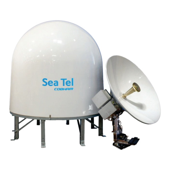
BROADBAND-AT-SEA VSAT ANTENNA SYSTEM
Sea Tel, Inc.
4030 Nelson Avenue
Concord, CA 94520
Tel: (925) 798-7979
Fax: (925) 798-7986
Web:
http://www.cobham.com/seatel
Sea Tel Inc is also doing business as Cobham Antenna Systems
May 3, 2013
INSTALLATION MANUAL
FOR SEA TEL 6012-71 C-BAND
Sea Tel Europe
Unit 1, Orion Industrial Centre
Wide Lane, Swaythling
Southampton, UK S0 18 2HJ
Tel: 44 (0)23 80 671155
Fax: 44 (0)23 80 671166
Web:
http://www.cobham.com/seatel
Document. No. 139107 Revision A
Advertisement
Table of Contents

Related Manuals for Sea Tel 6012-71 C-BAND


Summary of Contents for Sea Tel 6012-71 C-BAND
-
Page 1: Installation Manual
Southampton, UK S0 18 2HJ Fax: (925) 798-7986 Tel: 44 (0)23 80 671155 Web: http://www.cobham.com/seatel Fax: 44 (0)23 80 671166 Web: http://www.cobham.com/seatel Sea Tel Inc is also doing business as Cobham Antenna Systems May 3, 2013 Document. No. 139107 Revision A... - Page 2 Copyright © 2013 Sea Tel Inc All Rights Reserved. The information contained in this document is proprietary to Sea Tel, Inc.. This document may not be reproduced or distributed in any form without prior written consent of Sea Tel, Inc. The information in this document is subject to change without notice.
- Page 3 F: +1 (925) 798-7986 R&TTE Declaration of Conformity Sea Tel Inc. declares under our sole responsibility that the products identified below are in conformity with the requirements of: DIRECTIVE 1999/5/EC of the European Parliament and of the Council of 9 March 1999 on Radio equipment and Telecommunication Terminal Equipment and the mutual recognition of their conformity.
- Page 4 2009 version of FCC 47 C.F.R. § 25.221. Sea Tel hereby declares that the antennas listed below will meet the off-axis EIRP spectral density requirements of § 25.221 (a)(1)(i) with and N value of 1, when the following Input Power spectral density limitations are met: 1.5 Meter C Band, Models 6006, 6009, and 6012 are limited to -10 dBW/4kHz...
-
Page 5: Table Of Contents
Table of Contents 6012-71 Installation Manual 1. SERIES 12 KU-BAND SYSTEM CONFIGURATION(S) ......................1-1 1.1......................................1-1 YSTEM ABLES 1.2................................... 1-1 THER NPUTS TO THE YSTEM 1.3....................................1-1 YSTEM OMPONENTS 1.4. AMIP™) S : ................ 1-2 NTENNA ODEM NTERFACE ROTOCOL PECIFICATION... - Page 6 ARGET A DIFFERENT SATELLITE 11. OPTIMIZING CROSS-POL ISOLATION ............................11-1 11.1. O ..............................11-1 PTIMIZING ROSS SOLATION 12. SERIES 6012-71 C-BAND TECHNICAL SPECIFICATIONS ................... 12-1 12.1. 6012-71 S ..................................12-1 PECIFICATIONS 12.2. C ........................................12-10 ABLES 12.2.1. Antenna L-Band IF Coax Cables (Customer Furnished) .................. 12-10 13.
-
Page 7: Series 12 Ku-Band System Configuration(S)
Series 12 Ku-Band System Configuration(s) 6012-71 Installation Manual Series 12 Ku-Band System Configuration(s) The Series 12 Ku-Band Stabilized Antenna system is to be used for Transmit/Receive (TX/RX) satellite communications. It is comprised of two major groups of equipment: the Above Decks Equipment (ADE) and the Below Decks Equipment (BDE). There will also be interconnecting cables between the ADE &... -
Page 8: Open Antenna-Modem Interface Protocol (Openamip™) Specification
(proper option files) and the MXP/ICU (setup parameters) are compatible for the intended satellite(s). 1.4.2. Interface requirements: 1.4.2.1. Hardware Sea Tel Media Xchange Point (MXP) Any Satellite modem manufacturer that is compatible with OpenAMIP CAT5 Patch cable 1.4.2.2. Software Sea Tel MXP software version (latest). -
Page 9: Utilized Openamip Tm Commands
Set keep alive in seconds (0 = off) “a 5” i s1 s2 Set Antenna Vendor (s1) and device (s2) 2 parameters: “i Sea Tel DAC-2202” s b1 b2 Antenna Status: 2 parameters: “s 1 1” b1 is functional status and b2 is Tx allowed... - Page 10 6012-71 Installation Manual Series 12 Ku-Band System Configuration(s) This Page Intentionally Left Blank...
-
Page 11: Site Survey
Site Survey 6012-71 Installation Manual Site Survey There are three objective of the site survey. The first is to find the best place to mount the antenna and the BDE. The second is to identify the length and routing of the cables and any other items or materials that are required to install the system. The third is to identify any other issues that must be resolved before or during the installation. -
Page 12: Mounting Foundation
The height of the pedestal should be kept as short as possible, taking into account recommendations given in other Sea Tel Guidelines. The minimum height of the pedestal above a flat deck or platform to allow access into the radome for maintenance should be 0.6 meters (24 inches). -
Page 13: Mounting Height
2.5. Mast Configurations Sea Tel recommends mounting the ADE in a location that has both a clear line-of-sight to the target satellites in all potential azimuth/elevation ranges and sufficient support against vibration excitement. If possible, mounting the ADE pedestal directly to ship deckhouse structures or other box stiffened structures is preferred. However, in many cases, this imposes limits on the antenna system’s clear line-of-sight. -
Page 14: Vertical Masts
6012-71 Installation Manual Site Survey 2.5.1. Vertical Masts Vertical masts are a very ancient and common mast design. In essence, it is the mast derived from the sailing mast and adapted for mounting the ever-increasing array of antennae which ships need to communicate with the world. -
Page 15: Truss Mast
For every 100 kilograms of ADE weight over 250 kilograms, the depth of the platform stiffeners should be increased by 50 millimeters and thickness by 2 millimeters. Sea Tel does not have a recommended arrangement for a truss mast – the variability of truss mast designs means that each installation needs to be evaluated separately. -
Page 16: Ade/Bde Coaxial Cables
6012-71 Installation Manual Site Survey 2.8.1. ADE/BDE Coaxial Cables The first concern with the coaxial cables installed between the ADE & BDE is length. This length is used to determine the loss of the various possible coax, Heliax or fiber-optic cables that might be used. You should always provide the lowest loss cables to provide the strongest signal level into the satellite modem. -
Page 17: Grounding
Site Survey 6012-71 Installation Manual 2.9. Grounding All metal parts of the ADE shall be grounded to bare metal that is common to the hull of the ship. This is most commonly accomplished by attaching a ground wire/cable from the upper base plate ground point to a ground stud on the mounting pedestal/stanchion/mast near the base of the radome. - Page 18 6012-71 Installation Manual Site Survey This Page Intentionally Left Blank...
-
Page 19: Installation
Installation 6012-71 Installation Manual Installation Your antenna pedestal comes completely assembled in its radome. This section contains instructions for unpacking, final assembling and installing of the equipment. It is highly recommended that trained technicians install the system. The installation instructions for your system are below. 3.1. -
Page 20: Installing The Ade
6012-71 Installation Manual Installation 3.3. Installing the ADE The antenna pedestal is shipped completely assembled in its radome. Please refer to the entire Site Survey chapter of this manual. Base Hatch Access - Mounting the radome directly on the deck or platform prevents access to the hatch in the base of the radome unless an opening is designed into the mounting surface to allow such entry. -
Page 21: Grounding The Pedestal
Braid is the conductor of choice where flexibility is required. Sea Tel uses braid to cross axes of the antenna pedestal and to connect various subassemblies together. -
Page 22: Removing The Shipping/Stow Restraints Prior To Power-Up
6012-71 Installation Manual Installation 3.5. Removing the Shipping/Stow Restraints PRIOR to Power-Up The order the restraints are removed is not critical. CAUTION: There are three shipping/stow restraints on this antenna pedestal that MUST be removed, before energizing the antenna, for normal operation. 3.5.1. -
Page 23: Removing The El Shipping/Stow Restraint
Installation 6012-71 Installation Manual 3.5.2. Removing the EL Shipping/Stow Restraint The EL shipping/stow restraint is formed by a stow pin-bolt mounted through a bracket and is engaged into a hole/slot in the elevation driven sprocket when the dish is at zenith (90 degrees elevation). - Page 24 6012-71 Installation Manual Installation Remove the washer from the stow pin-bolt and thread one of the two hex nuts onto the bolt and tighten. Put one of the washers onto the stow pin-bolt and insert it into the bracket toward the elevation driven sprocket.
-
Page 25: Removing The Cl Shipping/Stow Restraint
Assure that the Gyro Compass output is turned OFF when handling and connecting wiring to the MXP. CAUTION - Allow only an authorized dealer to install or service the Sea Tel System components. Unauthorized installation or service can be dangerous and may... -
Page 26: Connecting The Below Decks Equipment
6012-71 Installation Manual Installation 3.7. Connecting the Below Decks Equipment Connect this equipment as shown in the System Block Diagram. Install the equipment in a standard 19 inch equipment rack or other suitable location. Optional slide rails are available. 3.7.1. Connecting the ADE AC Power Cable Connect the AC Power cable that supplies power to the ADE to a suitably rated breaker or UPS. -
Page 27: Other Bde Connections
Installation 6012-71 Installation Manual 3.7.3.8. J9 A/B Serial Computer RJ-45 Serial M&C connection. 3.7.3.9. J10C Modem RJ-45 Serial M&C connection to Satellite Modem Console Port. 3.7.3.10. J10D OBM RJ-45 Serial M&C connection to Out of Band Management equipment, if used. 3.7.3.11. - Page 28 6012-71 Installation Manual Installation • If this is a Dual Antenna installation configuration, you will have to balance the TX levels of the two antennas while online with the NOC (refer to procedure in the Dual Antenna Arbitrator manual). • It is strongly recommended that you download, and save, the system INI file (contains all of the system parameters for the ICU and the MXP).
-
Page 29: Configuring A Computer For The Mxp
Configuring a Computer for the MXP 6012-71 Installation Manual Configuring a Computer for the MXP The first thing you need to do is to configure your computer so that it will display the MXP screens. Follow these instructions to accomplish that. Connect a LAN cable to the back of your computer. - Page 30 6012-71 Installation Manual Configuring a Computer for the MXP From your computer desktop, click the Control Panel button. NOTE: The following displayed screen captures are form Window 7 OS, Your screens may differ, refer to your PC manual for changing network adapter settings. Click on “View network status and tasks”.
- Page 31 Configuring a Computer for the MXP 6012-71 Installation Manual Click on “Properties”. Double-Click on “Internet Protocol Version 4 (IPv4)”. 10. Click on “Use the following IP address:...
- Page 32 6012-71 Installation Manual Configuring a Computer for the MXP 11. In the IP Address boxes, enter “10.1.1.102” (This is for the IP address of your computer). NOTE: You could use 101, 102, 103, etc. as long as it is not the same as the address of the MXP, which is “10.1.1.100”...
- Page 33 17. Open your browser, and enter the URL: “10.1.1.100”. 18. At the log in screen enter the user name (Dealer, SysAdmin, or User). Contact Sea Tel Service for the password. 19. After you log in you will see the System Status...
- Page 34 6012-71 Installation Manual Configuring a Computer for the MXP This Page Intentionally Left Blank...
-
Page 35: Setup - Ship's Gyro Compass
Setup – Ship’s Gyro Compass 6012-71 Installation Manual Setup – Ship’s Gyro Compass The Ships Gyro Compass connection provides true heading (heading of the ship relative to true North) input to the system. This allows the ICU to target the antenna to a “true” Azimuth position to acquire any desired satellite. After targeting, this input keeps the antenna stabilized in Azimuth (keeps it pointed at the targeted satellite Azimuth). -
Page 36: If There Is No Ships Gyro Compass
6012-71 Installation Manual Setup – Ship’s Gyro Compass Click Save, at the bottom left area of the screen. 5.2. If there is NO Ships Gyro Compass Without heading input to the system the MXP will NOT be able to easily target, or stay stabilized ON, a “true” azimuth pointing angle. - Page 37 Setup – Ship’s Gyro Compass 6012-71 Installation Manual Turn on SAT REF Mode. (It must be turned on.) This combination of settings will cause “No Gyro” Search pattern to be use to find the desired satellite (refer to the setup – Searching chapter).
- Page 38 6012-71 Installation Manual Setup – Ship’s Gyro Compass This Page Intentionally Left Blank...
-
Page 39: Setup - Satellite Configuration
The satellite selection will in turn control the hardware on the antenna pedestal to select the correct TX & RX hardware and the correct tracking settings. Sea Tel provides quad-band LNBs as standard on the Series 12 Ku-Band antennas. Access the Satellite Configuration screen. - Page 40 6012-71 Installation Manual Setup – Satellite Configuration Enter the known skew for this satellite in degrees, leave at zero if this satellite is not skewed. 10. Select the desired type of search pattern to use for this satellite. 11. Select desired TX Polarity from the drop down menu.
- Page 41 Setup – Satellite Configuration 6012-71 Installation Manual 13. Assure that reflector is set to “Primary”. 14. Select Cross-Pol LNB (XPol) or Co-Pol LNB (CoPol) as is appropriate for this satellite. 15. Click the Save button to save this satellite. 16. Repeat as necessary for all of the satellites that the system may need to use as the ship travels.
- Page 42 6012-71 Installation Manual Setup – Satellite Configuration This Page Intentionally Left Blank...
-
Page 43: Setup - Home Flag
Setup – Home Flag 6012-71 Installation Manual Setup – Home Flag Home Flag is used to calibrate the relative azimuth value of the antenna to the bow line of the ship. This assures that the encoder input increments/decrements from this initialization value so that the encoder does not have to be precision aligned. When the antenna is pointed in-line with the bow (parallel to the bow) the “Relative”... -
Page 44: You Observe "Home" Pointing Is Left Of The Bow-Line
6012-71 Installation Manual Setup – Home Flag 7.1.1. You Observe “Home” Pointing is LEFT of the Bow-line: In this example, I observe that the Home position is short of the bow line. I estimate that it is about 45 degrees away. I target my desired satellite and record the Calculated Azimuth to be 180.5. -
Page 45: Entering A Large Value As Home Flag
Setup – Home Flag 6012-71 Installation Manual 7.1.3. Entering a large value as Home Flag If the amount of offset is greater than +/-5 degrees, enter it as Home Flag. If it is within +/-5 degrees, you could enter it in AZ TRIM, however, the amount of this error will cause you blockage zone(s) to be off by this amount &... -
Page 46: Entering A Small Value As Az Trim
6012-71 Installation Manual Setup – Home Flag 7.1.1. Entering a small value as AZ TRIM If the amount of offset is greater than +/-5 degrees, enter it as Home Flag. If it is within +/-5 degrees, you should enter it in AZ TRIM. Access the Reflector Configuration screen Use Auto Trim, or enter the small... -
Page 47: Setup - Blockage Zones
Setup – Blockage Zones 6012-71 Installation Manual Setup – Blockage Zones The Blockage Zones function inhibits the antenna from transmitting within certain pre-set zones. To set up the blockage zones go to the System Configuration screen. Enter a name for this particular blockage zone to help you identify it (ie “Mast”... - Page 48 6012-71 Installation Manual Setup – Blockage Zones This Page Intentionally Left Blank...
-
Page 49: Setup - Calibrating Targeting
Setup – Calibrating Targeting 6012-71 Installation Manual Setup – Calibrating Targeting In this chapter you will learn how to optimize the targeting of the antenna to taget on or near a desired satellite (within +/-1 degree). 9.1. AUTO TRIM The Auto Trim function will automatically calculate and set the required Azimuth and Elevation trim offset parameters required to properly calibrate the antennas display to the mechanical angle of the antenna itself, while peaked ON satellite. - Page 50 6012-71 Installation Manual Setup – Calibrating Targeting To activate the Auto Trim function go to the Reflector Configuration screen. Click on the Auto Trim button. When Auto Trim completes and enters the trim values for Azimuth and Elevation, Click SAVE...
-
Page 51: Manually Calibrating Targeting
Setup – Calibrating Targeting 6012-71 Installation Manual 9.2. Manually Calibrating Targeting Access the Satellite Search screen Assure that your Ship Latitude & Longitude (under ship position) and Heading (in the banner) settings in the MXP are correct. Target the desired satellite by selecting it from the drop down list. - Page 52 6012-71 Installation Manual Setup – Calibrating Targeting 10. Enter the Elevation Trim in the EL field. 11. Enter the Azimuth Trim in the AZ field. 12. Click Save. 13. Re-target the satellite several times to verify that targeting is now driving the antenna to a position that is within +/- 1.0 degrees of where the satellite signal is located.
-
Page 53: Quick Start Operation
Quick Start Operation 6012-71 Installation Manual Quick Start Operation If your system has been set up correctly, and if the ship has not moved since the system was used last, the system should automatically acquire the satellite from a cold (power-up) start. Once the satellite has been acquired, the modem then should achieve lock and you should be able to use the system. - Page 54 6012-71 Installation Manual Quick Start Operation Not finding a signal greater than Threshold, the bar graph will stay red and the antenna will reach the end of the prescribed search pattern. The antenna will retarget and the cycle will repeat (Search Delay timeout, conduct search pattern followed by retarget).
-
Page 55: If Satellite Signal Is Found But Network Lock Is Not Achieved
Quick Start Operation 6012-71 Installation Manual 10.3. If satellite signal is found but network lock is NOT achieved: The Tracking LED will flash for a short period of time (Search Delay) followed by the Search LED coming The ICU will automatically move the antenna in the selected Search pattern until it receives a signal value that is greater than the threshold... -
Page 56: T Otarget A Different Satellite
6012-71 Installation Manual Quick Start Operation If the Latitude & Longitude values are not correct, access the Communication Interfaces screen and enter the ships Latitude & Longitude position in the fields provided. Click Save. If the Heading value is not correct, enter the correct value in the lower left field of the Communication Interfaces screen. - Page 57 Quick Start Operation 6012-71 Installation Manual When you make that selection you will see the temporary message: Acquiring Satellite Signal…Please Wait Shortly after that you will see the temporary message: Satellite Signal Found. Modem Lock: LOCKED 10-5...
- Page 58 6012-71 Installation Manual Quick Start Operation This Page Intentionally Left Blank 10-6...
-
Page 59: Optimizing Cross-Pol Isolation
Optimizing Cross-Pol Isolation 6012-71 Installation Manual Optimizing Cross-Pol Isolation Now that all of the other setup items have been checked and changed as necessary, it is time to contact the NOC to arrange for cross-pol isolation testing and whatever other commissioning the NOC asks for. Read this procedure thoroughly before you are asked to begin. - Page 60 6012-71 Installation Manual Optimizing Cross-Pol Isolation Double check with the NOC to assure that cross-pol is still optimized. Conduct any other testing as directed by the NOC (ie P1dB compression). 11-2...
-
Page 61: Series 6012-71 C-Band Technical Specifications
Series 6012-71 C-Band Technical Specifications 6012-71 Installation Manual Series 6012-71 C-Band Technical Specifications The specifications of your antenna system are below. 12.1. 6012-71 Specifications Above Decks Equipment System Weight (ADE) M AX Weight 362-9 kg / 800 Lbs (81" Radome) - Page 62 Pitch 10° Fixed Relative Azimuth (Heading) 0, 45 and 90° with respect to roll input Mounting Height Sea Tel recommends you do not exceed tangential accelerations of 0.5G (See below chart) Antenna Reflector C-Band Type Spun Aluminum axis symmetric reflector Diameter 1.47 m / 58"...
- Page 63 Series 6012-71 C-Band Technical Specifications 6012-71 Installation Manual Norsat 3000 Series C-Band LNB Sea Tel Part Number: 124556-1 Gain (typical) 58 dBm Noise temperature maximum 15K to 35K Power requirements +15 to +24 V supplied through center conductor of IF cable...
- Page 64 6012-71 Installation Manual Series 6012-71 C-Band Technical Specifications Power Supply (ADE) A/C Input Voltage 85-264 VAC, 47-63Hz, single phase Voltage 24 VDC, 150W Wattage 150W (total) Current Capacity 13.0A (total) GPS (On Board) Waterproof IPX7 Operating Temperature -30°C to +60°C Storage Temperature -40°C to +60°C...
- Page 65 Series 6012-71 C-Band Technical Specifications 6012-71 Installation Manual Status LEDs PCU Status Diagnostic Status of the PCU Modem Status Configuration & Diagnostic Status of the Modem Integrated SCPC Receiver Tuning Range 950 to 1950 MHz in 1 KHz increments Input RF Level...
- Page 66 6012-71 Installation Manual Series 6012-71 C-Band Technical Specifications Radome Assembly (81 Inch) w/ base frame Type Standard Material DIVINYCELL H100 Size Diameter 2.05m / 80.8" Height 1.9m / 75" W/O base frame Base Frame Height 0.55m / 21.75 in Hatch Size 45.7 x 71.7cm / 18 x 28 inch...
- Page 67 Series 6012-71 C-Band Technical Specifications 6012-71 Installation Manual Shock (Bump) Peak Accel., m/s2 Duration, ms Number of Cycles 100 ea. direction Directional Changes Transit Conditions Drop (Transit Shock) Complies with ISTA Standard Chemically Active Substances Environmental Condition Test Level Sea Salt...
- Page 68 6012-71 Installation Manual Series 6012-71 C-Band Technical Specifications MXP Box Connections Connections 4 Ethernet Port Back (RJ) 1 Ethernet Ports Internal (RJ) 1 Power Input 1 SMA Connector (RX from Rotary Joint to Diplexer) 1 F-Connector from Diplexer to Modem RX Port...
- Page 69 Series 6012-71 C-Band Technical Specifications 6012-71 Installation Manual BDE Environmental Conditions Temperature 0 to 40 degrees C Humidity Up to 100% @ 40 degrees C, Non-Condensing Power Requirements (MXP) 85-264 VAC, 47-63Hz, single phase, 100 Watts Power Requirements (DAC) 85-264 VAC, 47-63Hz, single phase, 160 Watts max...
-
Page 70: Cables
Antenna L-Band IF Coax Cables (Customer Furnished) Due to the loss across the length of the RF coaxes at L-Band, Sea Tel recommends the following 50 ohm coax cable types (and their equivalent conductor size) for our standard pedestal installations. Type N male... -
Page 71: Drawings
DRAWINGS 6012-71 Installation Manual DRAWINGS 13.1. 6012-71 C-Band Model Specific Drawings Drawing Title 138983-706_A System, 6012-71 in 81” Radome 13-3 138985-1_A System Block Diagram, 6012-71 13-5 138984_A Antenna Schematic, 6012-71 13-8 131790_A3 Pedestal Schematic, xx12 13-9 138986-1_A General Assembly 6012-71... - Page 72 6012-71 Installation Manual DRAWINGS This Page Intentionally Left Blank 13-2...
- Page 73 (NOT SHOWN) , 1 EA 137387-2 CUSTOMER DOC PACKET, SERIES 12 C-BAND (NOT SHOWN) , 1 EA 124766-1 DECAL KIT, 66-81 IN RADOME, SEA TEL (NOT SHOWN) , 1 EA 121711 A1 BALANCE WEIGHT KIT, BASIC, MEDIUM SYS (NOT SHOWN) ,...
- Page 74 Sea Tel - Strictly Confidential & Proprietary. Do Not Copy, Distribute or Disclose Without Prior 1:12 138983 Written Approval From Sea Tel. 6012-71 3rd ANGLE 1 OF 1 Copyright c Sea Tel, Inc 2011 - Unpublished Work FIRST USED: SHEET NUMBER PROJECTION...
- Page 75 SINGLE LEVEL MFG BILL OF MATERIAL FIND QTY PART NO REV DESCRIPTION REFERENCE DESIGNATOR 1 EA 138986-1 GENERAL ASS'Y, 6012-71 1 EA 131601-2 A1 ANTENNA ASS'Y, 6009-71, W/STI RADAR 1 EA 131559-2 FEED ASS'Y, 6009-71, W/STI RADAR FILT 1 EA 124556-1 A7 LNB, C-BAND PLL, NORSAT 3120N 1 EA 124571-X (REF ONLY) SSPB, C-BAND, MBUC, CODAN...
- Page 76 SINGLE LEVEL MFG BILL OF MATERIAL FIND QTY PART NO REV DESCRIPTION REFERENCE DESIGNATOR 1 EA 133014-1 FILTER, C-BAND, RX BP/RADAR REJECT 2 EA 113525 WAVEGUIDE ADAPTER, WR-137 TO N 1 EA 123699 ADAPTER, SWEPT 90 DEG, N(M) TO N(F), 1 EA 134725-1 ENCLOSURE ASS'Y, MXP 1 EA 134563-1...
- Page 80 SINGLE LEVEL MFG BILL OF MATERIAL FIND QTY PART NO REV DESCRIPTION REFERENCE DESIGNATOR 1 EA 138344-2 PEDESTAL ASS'Y, 6012, HD, DUAL BRIDGE 1 EA 138987-1 ELECT EQ FRAME ASS'Y, 6012-71 1 EA 131602-2 A2 ANTENNA INSTALL ASS'Y, 6009-71, STD 1 EA 113525 WAVEGUIDE ADAPTER, WR-137 TO N 1 EA 131645-1...
- Page 81 Sea Tel - Strictly Confidential & Proprietary. Do Not Copy, Distribute or Disclose Without Prior 1:10 138986 Written Approval From Sea Tel. DETAIL A 6012-71 3rd ANGLE 1 OF 2 Copyright c Sea Tel, Inc 2011 - Unpublished Work FIRST USED: SHEET NUMBER PROJECTION...
- Page 82 SIZE SCALE: DRAWING NUMBER 1:10 138986 2 OF 2 SHEET NUMBER...
- Page 83 SINGLE LEVEL MFG BILL OF MATERIAL FIND QTY PART NO REV DESCRIPTION REFERENCE DESIGNATOR 1 EA 123861 MOUNTING PLATE 2 EA 126288-17 UNISTRUT, 1-5/8 H-CHANNEL, 17 IN, AL 1 EA 134735-1 E2 ENCLOSURE ASS'Y, ICU 1 EA 138883-1 MOUNTING ASS'Y, TEE-BRIDGE PWR SPLITT 1 EA 131374-2 WEIGHT, COUNTER, 1-1/2 X 1-1/2 X 17 8 EA 126279-3...
- Page 84 Sea Tel - Strictly Confidential & Proprietary. Do Not Copy, Distribute or Disclose Without Prior 138877 Written Approval From Sea Tel. 6012-44 3rd ANGLE 1 OF 1 Copyright c Sea Tel, Inc 2011 - Unpublished Work FIRST USED: SHEET NUMBER PROJECTION...
- Page 85 SINGLE LEVEL MFG BILL OF MATERIAL FIND QTY PART NO REV DESCRIPTION REFERENCE DESIGNATOR 1 EA 123861 MOUNTING PLATE 2 EA 126492 BAR, CODAN BUC, INTERFACE 2 EA 126288-12 UNISTRUT, 1-5/8 H-CHANNEL, 12 IN, AL 1 EA 126502 BRACE, CROSS ANGLE, BUC MOUNTING, 9.0 1 EA 126501 D BRACE, CROSS ANGLE, BUC MOUNTING, 18.
- Page 86 Do Not Copy, Distribute or Disclose Without Prior 131558 Written Approval From Sea Tel. FURTHEST EXTENT OF THEIR RANGE IN THE 6009 DIRECTION SHOWN. 3rd ANGLE 1 OF 1 Copyright c Sea Tel, Inc 2011 - Unpublished Work FIRST USED: SHEET NUMBER PROJECTION...
- Page 87 SINGLE LEVEL MFG BILL OF MATERIAL FIND QTY PART NO REV DESCRIPTION REFERENCE DESIGNATOR 2 EA 108724-1 C2 PLATE, COUNTER WEIGHT, 3/4 X 7-1/4 X 1 EA 108724-3 C2 PLATE, COUNTER WEIGHT, 1/2 X 7-1/4 X 1 EA 118560 D WEIGHT, TRIM, 1 x 3.38 x 3, 2.8 LBS 1 EA 112573-2 D WEIGHT, TRIM, 1/2 x 2.75 x 3, 1.17 LB 3 EA 108519-3...
- Page 88 REVISION HISTORY REV ECO# DATE DESCRIPTION 7398 07/14/10 RELEASED TO PRODUCTION. NO PRIOR REVISION. PARTIAL EQUIPMENT FRAME SHOWN AS REFERENCE ONLY 69 68 50 58 DRAWN BY: UNLESS OTHERWISE SPECIFIED DIMENSIONS ARE IN INCHES. DETAIL A X.X = .050 DRAWN DATE: 07/14/10 X.XX = .020 Tel.
- Page 89 SINGLE LEVEL MFG BILL OF MATERIAL FIND QTY PART NO REV DESCRIPTION REFERENCE DESIGNATOR 1 EA 130306-1 A4 RADOME TOP FAB, 81 IN, TUNED, WHITE 1 EA 120881 HARDWARE KIT, 80.8 INCH RADOME 3 EA 117762-1 SILICONE ADHESIVE, WHT RTV 122, 10.1 RADOME ASS'Y, 81 IN, TUNED, WHITE PROD FAMILY EFF.
- Page 91 SINGLE LEVEL MFG BILL OF MATERIAL FIND QTY PART NO REV DESCRIPTION REFERENCE DESIGNATOR 1 EA 119707-1 BASE FRAME ASS'Y, 80.8 INCH, STEEL, 2 1 EA 124460-1 A3 RADOME BASE FAB, 80.8 INCH, WHITE, A/ 1 EA 123729-2 H A/C INSTALL ASS'Y, EXTERNAL, 81" BASE 1 EA 120191-2 C4 RADOME PAN ACCESS ASS'Y, WHITE 5 EA 124903-1...
- Page 95 Procedure, General Strain Relief Installation Purpose. To define the installation procedure for installing strain reliefs in the base pan of the radome. Scope. This installation procedure applies to fiberglass base pans used in Sea Tel’s 75”, 81” and 110” base frames. Tools/materials.
- Page 96 Procedure, General Strain Relief Installation Sealing the hole edges CAUTION: Cut edges can allow water and/or ice ingress and weaken the fiberglass laminate or structural foam. It is essential to seal all cut edges thoroughly with fiberglass resin to preserve the base pans structural strength. CAUTION: Fiberglass paste or RTV silicone sealant will not wick into and seal the fiberglass strands as well as fiberglass resin, ONLY use fiberglass resin (such as TAP PLASTICS MARINE VINYL ESTER, or equivalent) for sealing the cut edges.
- Page 97 SINGLE LEVEL MFG BILL OF MATERIAL FIND QTY PART NO REV DESCRIPTION REFERENCE DESIGNATOR 1 EA 109258-8 G2 STRAIN RELIEF 1 EA 124904 LOCKNUT 1 EA 124905 SEALING RING 1 EA 124354-1 A1 RUBBER STOPPER 1 EA 114580-033 WASHER, FLAT, 1/2, S.S. STRAIN RELIEF ASS'Y PROD FAMILY EFF.
- Page 98 REVISION HISTORY ECO# DATE DESCRIPTION 1-9-06 RELEASED TO PRODUCTION, WAS REV X3. 5266 8-7-06 ADD NOTE 3. 5872 10-11-07 DELETED ADHESIVE APPLICATION NOTE, NOTE 2 RE-WRITTEN. 5-7-10 CORRECTED MODEL, UPDATED TITLE BLOCK. FIBERGLASS RADOME BASE OUTSIDE RADOME NOTES: UNLESS OTHERWISE SPECIFIED DISCARD RUBBER BUSHING AND PLASTIC RETAINING RING FROM STRAIN RELIEF AT ASSEMBLY.
- Page 99 SINGLE LEVEL MFG BILL OF MATERIAL FIND QTY PART NO REV DESCRIPTION REFERENCE DESIGNATOR 1 EA 138633-4 BDE CABLE KIT, 4012GX (MXP) 1 EA 136872 A1 BRACKET ASS'Y, CONNECTOR, RACK MOUNT BELOW DECK KIT, 4012GX (MXP) PROD FAMILY EFF. DATE DRAWING SHT 1 OF COMMON...
Need help?
Do you have a question about the 6012-71 C-BAND and is the answer not in the manual?
Questions and answers