
Related Manuals for Avalue Technology ECM-SKLH


Summary of Contents for Avalue Technology ECM-SKLH
- Page 1 ECM-SKLH Intel® Skylake H Processor 3.5” Micro Module User’s Manual Ed – 02 November 2016 Part No. E2047392801R...
- Page 2 Disclaimer Avalue Technology Inc. reserves the right to make changes, without notice, to any product, including circuits and/or software described or contained in this manual in order to improve design and/or performance. Avalue Technology assumes no responsibility or liability for the...
- Page 3 Applications that are described in this manual are for illustration purposes only. Avalue Technology Inc. makes no representation or warranty that such application will be suitable for the specified use without further testing or modification.
- Page 4 A product returned without proof of the purchase date is not eligible for warranty service. Write the RMA number visibly on the outside of the package and ship it prepaid to your dealer. 4 ECM-SKLH User’s Manual...
-
Page 5: Table Of Contents
Battery connector (JBAT) ......................28 2.3.19 Audio connector (JAUDIO) ......................28 Signal Description – Audio connector (JAUDIO) ..............28 2.3.19.1 3.BIOS Setup ........................29 Introduction ......................30 Starting Setup ......................30 Using Setup ......................31 Getting Help ......................32 ECM-SKLH User’s Manual... - Page 6 3.6.3.2.2 USB Configuration ......................... 60 3.6.3.2.3 HD Audio Configuration ......................60 3.6.4 Security ............................61 3.6.4.1 Secure Boot menu ......................... 62 3.6.5 Boot .............................. 63 3.6.6 Save and exit ..........................64 3.6.6.1 Save Changes and Reset ...................... 64 6 ECM-SKLH User’s Manual...
- Page 7 Install Chipset Driver ....................66 Install ME Driver ...................... 67 Install VGA Driver ....................68 Install Audio Driver (For Realtek ALC233) .............. 69 Install Ethernet Driver ....................70 Install RST Driver ....................72 5. Mechanical Drawing ....................74 ECM-SKLH User’s Manual...
-
Page 8: Getting Started
1.2 Packing List Before you begin installing your single board, please make sure that the following materials have been shipped: 1 x 3.5” ECM-SKLH Micro Module 1 x DVD-ROM contains the followings: ... -
Page 9: Document Amendment History
User’s Manual 1.3 Document Amendment History Revision Date Comment January 2016 Avalue Initial Release September 2016 Avalue Update Setting Jumpers & Connectors ECM-SKLH User’s Manual... -
Page 10: Manual Objectives
We strongly recommend that you study this manual carefully before attempting to set up ECM-SKLH or change the standard configurations. Whilst all the necessary information is available in this manual we would recommend that unless you are confident, you contact your supplier for guidance. -
Page 11: System Specifications
Realtek ALC233 HD codec Supports 2.1-CH Audio Internal AMP, Class-D amplifier has 2 Watt (rms)/4Ω per channel output Audio Amp Line in, Line-Out, Mic in Ethernet 1 x Intel I210AT GbE controller LAN Chip 1 x Intel I219LM Gigabit Ethernet PHY ECM-SKLH User’s Manual 11... - Page 12 0°C ~ 60°C Temp. Storage Temp. -40°C ~ 75°C Operating 0% ~ 90% relative humidity, non-condensing Humidity Size (L x W) 5.7" x 4" (146mm x 101mm) Weight 0.44lbs (0.2kg) Note: Specifications are subject to change without notice. 12 ECM-SKLH User’s Manual...
-
Page 13: Architecture Overview-Block Diagram
User’s Manual 1.6 Architecture Overview—Block Diagram The following block diagram shows the architecture and main components of ECM-SKLH. ECM-SKLH User’s Manual 13... -
Page 14: Hardware Configuration
ECM-SKLH User’s Manual 2. Hardware Configuration 14 ECM-SKLH User’s Manual... -
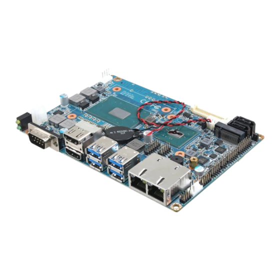
Page 15: Product Overview
User’s Manual 2.1 Product Overview ECM-SKLH User’s Manual 15... - Page 16 ECM-SKLH User’s Manual 16 ECM-SKLH User’s Manual...
-
Page 17: Jumper And Connector List
2 x 1 wafer, pitch 1.25 mm CPU fan connector 4 x 1 wafer, pitch 2.54 mm CPU_FAN System fan connector 4 x 1 wafer, pitch 2.54mm SYS_FAN Audio connector 8 x 2 header, pitch 2.00 mm JAUDIO ECM-SKLH User’s Manual 17... - Page 18 2 x 2 wafer, pitch 4.20 mm SATAPW1/2 SATA power header 1/2 2 x 1 wafer, pitch 2.00 mm Serial ATA connector 1/2 SATA1/2 M.2 KEY-B 2242 connector NGFF_B Full size Mini-PCI-e connector MPCIE SODIMM DDR4 SODIMM socket 18 ECM-SKLH User’s Manual...
-
Page 19: Setting Jumpers & Connectors
User’s Manual 2.3 Setting Jumpers & Connectors 2.3.1 AT/ ATX Input power select (JAT1) 2.3.2 Serial port 1 pin9 signal select (JRI) Ring* +12V * Default ECM-SKLH User’s Manual 19... -
Page 20: Clear Cmos (Jcmos)
ECM-SKLH User’s Manual 2.3.3 Clear CMOS (JCMOS) Protect* Clear CMOS * Default 2.3.4 LCD backlight brightness adjustment (JVR) DC Mode* PWM Mode * Default 20 ECM-SKLH User’s Manual... -
Page 21: Lcd Inverter Connector (Jbkl)
User’s Manual 2.3.5 LCD Inverter connector (JBKL) Signal VBRIGHT BKLEN +12V 2.3.6 CPU fan connector (CPU_FAN) Signal +12V EC_TACH0 FAN_PWM0 ECM-SKLH User’s Manual 21... -
Page 22: System Fan Connector (Sys_Fan)
ECM-SKLH User’s Manual 2.3.7 System fan connector (SYS_FAN) Signal +12V EC_TACH1 FAN_PWM1 2.3.8 Serial port 2 connector (JCOM2) Signal PIN PIN Signal COM_DCD# COM_RXD# COM_TXD COM_DTR# COM_DSR# COM_RTS# COM_CTS# COM_RI# 22 ECM-SKLH User’s Manual... -
Page 23: Serial Port 2 In Rs-422/485 Mode (J422_485)
Serial port 2 in RS-422/485 mode (J422_485) Signal PIN PIN Signal 485-422_TXDN 422_RXDN 485-422_TXDP 422_RXDP 2.3.10 General purpose I/O connector (JDIO) Signal PIN PIN Signal DIO_GP10 DIO_GP20 DIO_GP11 DIO_GP21 DIO_GP12 DIO_GP22 DIO_GP13 DIO_GP23 SMB_CLK_VCC 10 SMB_DATA_VCC ECM-SKLH User’s Manual 23... -
Page 24: Sata Power Header 1/2 (Satapw1/2)
ECM-SKLH User’s Manual 2.3.11 SATA Power header 1/2 (SATAPW1/2) Signal SATAPW1 2.3.12 Power connector (PWR) Signal PIN PIN Signal +12V +12V 24 ECM-SKLH User’s Manual... -
Page 25: On-Board Header For Usb2.0 (Jusb)
User’s Manual 2.3.13 On-board header for USB2.0 (JUSB) Signal PIN PIN Signal +5VSB USB_DN4 USB_DP4 USB_DP5 USB_DN5 +5VSB 2.3.14 LPC connector (JLPC) Signal PIN PIN Signal LPC_AD0 +3.3V LPC_AD1 PLTRST# LPC_AD LPC_LFRAME# LPC_AD03 CLK_PCI_JLPC SERIRQ +5VSB ECM-SKLH User’s Manual 25... -
Page 26: Lvds Connector (Jlvds)
ECM-SKLH User’s Manual 2.3.15 LVDS connector (JLVDS) Signal PIN PIN Signal +12V +12V LVDS_CLK2_N LVDS_CLK1_N LVDS_CLK2_P LVDS_CLK1_P LVDS_DATA7_N LVDS_DATA6_N LVDS_DATA7_P LVDS_DATA6_P LVDS_DATA5_N LVDS_DATA4_N LVDS_DATA5_P LVDS_DATA4_P LVDS_DATA3_N LVDS_DATA2_N LVDS_DATA3_P LVDS_DATA2_P LVDS_DATA1_N LVDS_DATA0_N LVDS_DATA1_P LVDS_DATA0_P LVDS_DDC_CLK LVDS_DDC_DATA +3.3V +3.3V 26 ECM-SKLH User’s Manual... -
Page 27: Miscellaneous Setting Connector (Jfp)
User’s Manual 2.3.16 Miscellaneous setting connector (JFP) Signal PIN PIN Signal PWR_BTN_IN_EC# RESET_BT +5VSB PWR_LED- HDD_LED# 2.3.17 SPI header (JSPI) Signal PIN PIN Signal +3.3VSB SPI_CS0# SPI_CLK SPI_SO SPI_SI HOLD# EC_SMCLK_DEBUG 10 EC_SMDAT_DEBUG ECM-SKLH User’s Manual 27... -
Page 28: Battery Connector (Jbat)
MIC1-R-IN MIC1-L-IN FRONT-JD LINE1-JD MIC1-JD HD_AGND SPK_L+ SPK_R+ SPK_L- SPK_R- 2.3.19.1 Signal Description – Audio connector (JAUDIO) Signal Signal Description LINE1-JD AUDIO IN (LINE_RIN/LIN)sense pin FRONT-JD AUDIO Out(ROUT/LOUT) sense pin MIC1-JD MIC IN (MIC_RIN/LIN) sense pin 28 ECM-SKLH User’s Manual... -
Page 29: Bios Setup
User’s Manual 3.BIOS Setup ECM-SKLH User’s Manual 29... -
Page 30: Introduction
If the message disappears before you respond and you still wish to enter Setup, restart the system to try again by turning it OFF then ON or pressing the "RESET" button on the system case. You may also restart by simultaneously pressing <Ctrl>, <Alt>, and <Delete> keys. 30 ECM-SKLH User’s Manual... -
Page 31: Using Setup
Note: Some of the navigation keys differ from one screen to another. To Display a Sub Menu Use the arrow keys to move the cursor to the sub menu you want. Then press <Enter>. A “” pointer marks all sub menus. ECM-SKLH User’s Manual 31... -
Page 32: Getting Help
Even a seemingly small change to the chipset setup has the potential for causing you to use the override. 32 ECM-SKLH User’s Manual... -
Page 33: Bios Setup
<Enter> to accept and enter the sub-menu. 3.6.1 Main Menu This section allows you to record some basic hardware configurations in your computer and set the system clock. ECM-SKLH User’s Manual 33... -
Page 34: System Language
Note: The BIOS setup screens shown in this chapter are for reference purposes only, and may not exactly match what you see on your screen. Visit the Avalue website (www.avalue.com.tw) to download the latest product and BIOS information. 34 ECM-SKLH User’s Manual... -
Page 35: Advanced Menu
3.6.2.1 Trusted Computing Item Options Description Enables or Disables BIOS support for security Disable, Security Device Support device. O.S. will not show Security Device. TCG Enable[Default] EFI protocol and INT1A interface will not be ECM-SKLH User’s Manual 35... -
Page 36: Apci Settings
Description Enable ACPI Auto Disabled[Default], Enables or Disables BIOS ACPI Auto Configuration Enabled Configuration. Enables or Disables System ability to Disabled Hibernate (OS/S4 Sleep State). This Enable Hibernation Enabled[Default], option may be not effective with some 36 ECM-SKLH User’s Manual... -
Page 37: It8528 Super Io Configuration
ACPI Low Power S0 Idle Enabled Idle Support. 3.6.2.3 IT8528 Super IO Configuration You can use this item to set up or change the IT8528 Super IO configuration for serial ports. Please refer to 3.6.2.3.1~ 3.6.2.3.2 for more information. ECM-SKLH User’s Manual 37... -
Page 38: Serial Port 1 Configuration
Set Parameters of Serial Port 1 (COMA). Serial Port 2 Configuration Set Parameters of Serial Port 2 (COMB). 3.6.2.3.1 Serial Port 1 Configuration Item Option Description Enabled[Default], Serial Port Enable or Disable Serial Port (COM). Disabled 3.6.2.3.2 Serial Port 2 Configuration 38 ECM-SKLH User’s Manual... -
Page 39: Amt Configuration
SPI device. Disabled[Default] OEMFLag Bit 1: Enable/Disable BIOS BIOS Hotkey Pressed Enabled, hotkey press. Disabled[Default] OEMFLag Bit 2: Enable/Disable MEBx MEBx Selection Screen Enabled, selection screen. Disabled[Default] OEMFlag Bit 15: Un-Configure ME without Un-Configure ME Enabled, password. ECM-SKLH User’s Manual 39... -
Page 40: Pch-Fw Configuration
Selects TPM device: PTT or dTPM. PTT – Enables PTT in SkuMgr dTPM 1.2 – dTPM 1.2[Default], TPM Device Selection Disables PTT in SkuMgr Warning! PTT/dTPM will be disabled and all data saved on it will be lost. 40 ECM-SKLH User’s Manual... -
Page 41: Firmware Update Configuration
User’s Manual 3.6.2.5.1 Firmware Update Configuration Item Option Description Disabled [Default], ME FW Image Re-Flash Enable/Disable Me FW Image Re-Flash function. Enabled 3.6.2.6 H/W Monitor ECM-SKLH User’s Manual 41... -
Page 42: Smart Fan Mode Configuration
Description Enabled, Smart Fan Function Enables or Disables Smart Fan. Disabled[Default] 3.6.2.6.1 Smart Fan Mode Configuration Item Option Description Manual Mode[Default]/, CPU Smart Fan Mode Select (Manual, Mode CPU Smart Fan Mode Mode 01/02/03/04/05 1~Mode 20). 42 ECM-SKLH User’s Manual... -
Page 43: S5 Rtc Wake Settings
Enable or disable System wake on alarm event. Select Disabled[Default], Fixed Time, system will wake on the hr::min::sec specified. Wake system from S5 Fixed Time Select Dynamic Time, System will wake on the current time Dynamic Time + Increase minute(s). ECM-SKLH User’s Manual 43... - Page 44 Wake up hour 0-23 3pm. Select 0-23 For example enter 3 for 3am and 15 for Wake up minute 0-23 3pm. Select 0-23 For example enter 3 for 3am and 15 for Wake up second 0-23 3pm. 44 ECM-SKLH User’s Manual...
-
Page 45: Serial Port Console Redirection
Select Dynamic Time, System Dynamic Time[Default] will wake on the current time + Increase minute(s). Wake up minute increase 1-5. 3.6.2.8 Serial Port Console Redirection Item Options Description Disabled[Default], Console Redirection Console Redirection Enable or Disable. Enabled ECM-SKLH User’s Manual 45... -
Page 46: Cpu Configuration
Use the CPU configuration menu to view detailed CPU specification and configure the CPU. Item Options Description Enabled for Windows XP and Linux (OS Disabled, optimized for Hyper- Threading Hyper-threading Enabled[Default] Technology) and Disabled for other OS (OS not optimized for Hyper- Threading 46 ECM-SKLH User’s Manual... -
Page 47: Intel Txt Configuration
Max Battery Max Non-Turbo Select the performance state that the BIOS Boot performance mode Performance[Default] will set before OS handoff. Turbo Performance Disabled[Default], Enables or Disables Intel® TXT(LT) Intel TXT(LT) Support Enabled support. 3.6.2.10 Intel TXT Configuration ECM-SKLH User’s Manual 47... -
Page 48: Sata Configuration
Aggressive LPM Support Disabled state. Enabled[Default] Port 0/1/2/3 Enable or Disable SATA Port. Disabled, Hard Disk Drive [Default] Identify the SATA port is connected to Solid SATA Device Type Solid State Drive State Drive or Hard Disk Drive. 48 ECM-SKLH User’s Manual... -
Page 49: Network Stack Configuration
Enable/Disable UEFI Network Stack. Disabled[Default] Item Options Description Enabled[Default] Network Stack Enable/Disable UEFI Network Stack. Disabled Enable Ipv4 PXE Boot Support. If disabled Enabled[Default] Ipv4 PXE Support Disabled IPV4 PXE boot option will not be created. ECM-SKLH User’s Manual 49... -
Page 50: Csm Configuration
Wait time to press ESC key to abort the PXE PXE boot wait time boot. Number of times presence of media will be Media detect count checked. 3.6.2.13 CSM Configuration Item Options Description Enabled CSM Support Enable/Disable CSM Support. Disabled[Default] 50 ECM-SKLH User’s Manual... - Page 51 Legacy[Default] Do not launch Controls the execution of UEFI and Legacy Video UEFI Video OpROM. Legacy[Default] Do not launch Determines OpROM execution policy for Other PCI devices UEFI devices other than Network, Storage, or Legacy[Default] Vide. ECM-SKLH User’s Manual 51...
-
Page 52: Usb Configuration
Mass storage device emulation type. ‘AUTO’ Auto[Default] Floppy enumerates devices according to their media Mass Storage Devices Forced FDD format. Optical drives are emulated as ‘CDROM’, drives with no media will be Hard Disk CD-ROM emulated according to a drive type. 52 ECM-SKLH User’s Manual... -
Page 53: Chipset
User’s Manual 3.6.3 Chipset 3.6.3.1 System Agent (SA) Configuration Item Option Description Enabled[Default] VT-d VT-d capability. Disabled Enabled[Default] GMM Device (B0:D8:F0) Enable/Disable SA GMM Device. Disabled ECM-SKLH User’s Manual 53... -
Page 54: Graphics Configuration
Port1-EDP to LVDS (Chrotel 7511) CH7511 EDID Panel Option 800x480 18/1 Panel EDID Option. 1920x1080 18/2 1280x1024 24/2 1440x900 18/2 1600x1200 24/2 1366x768 24/1 1920x1080 24/2 1680x1050 24/2 Backlight brightness (%) Select LVDS back light PWM duty. 50%[Default] 54 ECM-SKLH User’s Manual... -
Page 55: Dmi/Opi Configuration
300 Hz 400 Hz 500 Hz 700 Hz LVDS Back Light PWM Select LVDS back light PWM Frequency Frequency. 3.6.3.1.2 DMI/OPI Configuration Item Option Description Auto[Default] Gen1 DMI Max Link Speed Set DMI Speed Gen1/Gen2/Gen3. Gen2 Gen3 ECM-SKLH User’s Manual 55... -
Page 56: Memory Configuration
SA GV disabled, MR only runs tasks from Fixed High Low or High point. Enabled[Default] MRC default[Default] System Agent Geyserville. Set frequency for SA GV Low Freq /1067/1200/1333/1400/1600 low point. Default 1067 for LPDDR3/DDR3, /1800/1867 1333 for DDR4. 56 ECM-SKLH User’s Manual... -
Page 57: Gt- Power Management Control
User’s Manual 3.6.3.1.4 GT- Power Management Control Item Option Description Enabled[Default] RC6 (Render Standby) Check to enable render standby support. Disabled 3.6.3.2 PCH-IO Configuration ECM-SKLH User’s Manual 57... -
Page 58: Pci Express Configuration
Serial IRQ Mode Configure Serial IRQ Mode. Continuous[Default] 3.6.3.2.1 PCI Express Configuration Item Option Description Disabled Enable/Disable the control of Active State DMI Link ASPM Control Enabled[Default] Power Management on SA side of the DMI Link. 58 ECM-SKLH User’s Manual... - Page 59 PCI Express L1 Substates settings. L1.2 L1.1 & L1.2[Default], Auto[Default] Gen1 PCIe Speed Select PCI Express port speed. Gen2 Gen3 Detect Non-Compliance PCI Express Disabled[Default], Detect Non-Compliance Device Device. If enable, it will take more time at Enabled POST time. ECM-SKLH User’s Manual 59...
-
Page 60: Usb Configuration
Disabled[Default], and root ports for faster enumeration. Option to disable Compliance Mode. Default FALSE[Default], XHCI Disable Compliance Mode is FALSE to not disable Compliance Mode. TRUE Set TRUE to disable Compliance Mode. 3.6.3.2.3 HD Audio Configuration 60 ECM-SKLH User’s Manual... -
Page 61: Security
Disabled[Default] Audio DSP Enable/Disable Audio DSP. Enabled Disabled[Default] Disconnects SDI2 signal to hide/disable iDisplay Audio Disconnect Enabled iDisplay Audio Code. 3.6.4 Security Administrator Password Set setup Administrator Password User Password Set User Password ECM-SKLH User’s Manual 61... -
Page 62: Secure Boot Menu
1.System running in User mode Secure Boot Enabled with enrolled Platform Key(PK) 2.CSM function is disabled. Secure Boot mode selector. ‘Custom’ Mode enables users to Standard Secure Boot Mode Custom[Default] change Image Execution policy and manage Secure Boot Keys. 62 ECM-SKLH User’s Manual... -
Page 63: Boot
Enables or disables boot with initialization of a Disabled[Default] Fast Boot minimal set of devices required to launch active Enabled boot option. Has no effect for BBS boot options. Boot Option #1/2 Set the system boot order. ECM-SKLH User’s Manual 63... -
Page 64: Save And Exit
This option restores all BIOS settings to the factory default. This option is useful if the controller exhibits unpredictable behavior due to an incorrect or inappropriate BIOS setting. 3.6.6.4 Launch EFI Shell from filesystem device Attempts to Launch EFI Shell application (Shellx64.efi) from one of the available filesystem devices. 64 ECM-SKLH User’s Manual... -
Page 65: Drivers Installation
User’s Manual 4. Drivers Installation Note: Installation procedures and screen shots in this section are for your reference and may not be exactly the same as shown on your screen. ECM-SKLH User’s Manual 65... -
Page 66: Install Chipset Driver
Windows 10 operation system. If the warning message appears while the installation Step 3. Click Install. process, click Continue to go on. Step 4. Setup completed. Step1. Click Next. Step 2. Click Accept. 66 ECM-SKLH User’s Manual... -
Page 67: Install Me Driver
If the warning message appears while the installation Step 3. Click Next to continue installation. process, click Continue to go on. Step 4. Click Finish to complete setup. Step1. Click Next to start installation. Step 2. Click Next. ECM-SKLH User’s Manual 67... -
Page 68: Install Vga Driver
Windows 10 operation system. Step 3. Click Next. Step 1. Click Next to continue installation. Step 4. Click Next. Step 5. Click Finish to complete setup. Step 2. Click Yes to accept license agreement. 68 ECM-SKLH User’s Manual... -
Page 69: Install Audio Driver (For Realtek Alc233)
\Driver_Audio\Realtek\ALC233\ECM-SKLH_Audio. Note: The installation procedures and screen shots in this section are based on Windows 10 operation system. Step 1. Click Next to continue setup. Step 2. Click Finish to complete the setup. ECM-SKLH User’s Manual 69... -
Page 70: Install Ethernet Driver
Note: The installation procedures and screen shots in this section are based on Windows 10 operation system. Step 3. Click Next. Step 4. Click Next. Step 1. Click Next. Step 5. Click Yes. Step 2. Click Next to proceed. 70 ECM-SKLH User’s Manual... - Page 71 User’s Manual Step 6. Click Install. Step 7. Click Finish to complete the setup. ECM-SKLH User’s Manual 71...
-
Page 72: Install Rst Driver
Note: The installation procedures and screen shots in this section are based on Windows 10 operation system. Step 3. Click Next. Step 1. Click Next to continue installation. Step 4. Click Next. Step 2. Click Next. Step 5. Click Next. 72 ECM-SKLH User’s Manual... - Page 73 User’s Manual Step 6. Click Next. Step 7. Click Finish to complete the setup. ECM-SKLH User’s Manual 73...
-
Page 74: Mechanical Drawing
ECM-SKLH User’s Manual 5. Mechanical Drawing 74 ECM-SKLH User’s Manual... - Page 75 User’s Manual Unit: mm ECM-SKLH User’s Manual 75...
Need help?
Do you have a question about the ECM-SKLH and is the answer not in the manual?
Questions and answers