
Related Manuals for Avalue Technology ECM-A50M B1


Summary of Contents for Avalue Technology ECM-A50M B1
- Page 1 ECM-A50M B1 3.5” AMD eOntario Module User’s Manual Ed –07 January 2019 Part No. E2047351804R...
- Page 2 Disclaimer Avalue Technology Inc. reserves the right to make changes, without notice, to any product, including circuits and/or software described or contained in this manual in order to improve design and/or performance. Avalue Technology assumes no responsibility or liability for the...
- Page 3 Applications that are described in this manual are for illustration purposes only. Avalue Technology Inc. makes no representation or warranty that such application will be suitable for the specified use without further testing or modification.
- Page 4 A product returned without proof of the purchase date is not eligible for warranty service. Write the RMA number visibly on the outside of the package and ship it prepaid to your dealer. 4 ECM-A50M B1 User’s Manual...
-
Page 5: Table Of Contents
General purpose I/O connector (JDIO) ..........34 2.4.18 Miscellaneous setting connector (JFP) ..........35 2.4.19 Keyboard & Mouse connector (JKBMS) ..........35 2.4.20 Low pin count interface connector (JLPC) ..........36 2.4.21 SPI connector (JSPI) ................36 ECM-A50M B1 User’s Manual 5... - Page 6 SB SATA Configuration ........... 62 3.6.3.3.2 SB USB Configuration ............. 63 3.6.3.3.3 SB HD Azalia Configuration ..........63 3.6.4 Boot ....................... 64 3.6.5 Security ....................65 3.6.5.1 Administrator Password ............65 3.6.5.2 User Password ................ 65 6 ECM-A50M B1 User’s Manual...
- Page 7 Boot override ................71 4. Drivers Installation....................... 72 Install Audio Driver (For Realtek ALC892)............ 73 Install Ethernet Driver (For Realtek 8111E) ..........74 Install Display Driver (For AMD Fusion Accelerated Processors) ....75 5. Mechanical Drawing ....................76 ECM-A50M B1 User’s Manual 7...
-
Page 8: Getting Started
— 1 x Serial ATA cable (7-pin, standard) — 1 x Serial ATA cable (15-pin, 2P/2.0mm) — 1 x Flat Cable 9P(M)-Dupont 10P/2.0mm 17cm 4 x D-sub Jack Screws DIP AUX-032 A1 W/Audio/4USB 8 ECM-A50M B1 User’s Manual... -
Page 9: Document Amendment History
ECM-A50M B1 User’s Manual 1.3 Document Amendment History Revision Date Comment B1 1 February 2012 Avalue Initial Release B1 2 January 2019 Avalue Update 2.3 Jumper and Connector List ECM-A50M B1 User’s Manual 9... -
Page 10: Manual Objectives
ECM-A50M B1 User’s Manual 1.4 Manual Objectives This manual describes in details Avalue Technology ECM-A50M Single Board. We have tried to include as much information as possible but we have not duplicated information that is provided in the standard IBM Technical References, unless it proved to be necessary to aid in the understanding of this board. -
Page 11: System Specifications
Display LCD Interface Dual channel 18/24-bit LVDS (transfer through DDI) TV-out Built-in Touch Screen (Optional) Chipset PenMount 6000 Touch Screen With 9-pin 2.0mm box header (can be selected to support 4/5/8-wire touch screen) Interface Audio ECM-A50M B1 User’s Manual 11... - Page 12 Power Type AT/ATX Operating Temp. 0 to 60C Storage Temp. -20~-80°C Operating Humidity 0%~90% relative humidity, non-condensing Size (L x W) 146 mm x 101 mm Weight Note: Specifications are subject to change without notice. 12 ECM-A50M B1 User’s Manual...
-
Page 13: Architecture Overview-Block Diagram
ECM-A50M B1 User’s Manual 1.6 Architecture Overview—Block Diagram The following block diagram shows the architecture and main components of ECM-A50M ECM-A50M B1 User’s Manual 13... -
Page 14: Hardware Configuration
ECM-A50M B1 User’s Manual 2. Hardware Configuration 14 ECM-A50M B1 User’s Manual... -
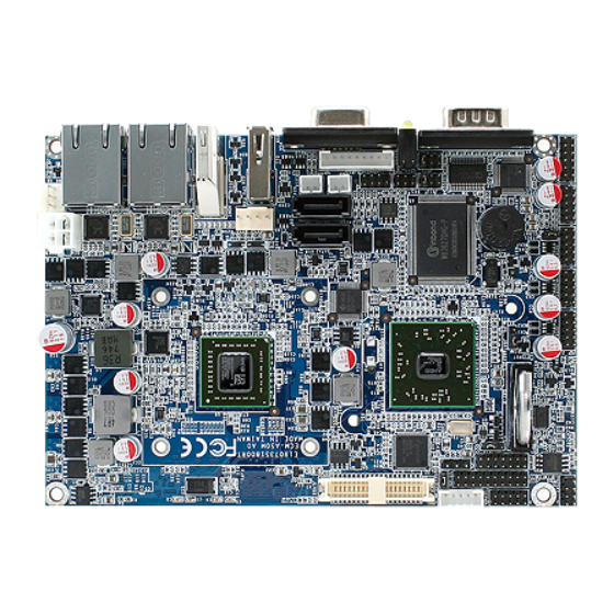
Page 15: Product Overview
ECM-A50M B1 User’s Manual 2.1 Product Overview ECM-A50M B1 User’s Manual 15... - Page 16 ECM-A50M B1 User’s Manual 16 ECM-A50M B1 User’s Manual...
-
Page 17: Installation Procedure
Window must be entered and configured correctly to match the particular system configuration. 7. If TFT panel display is to be utilized, make sure the panel voltage is correctly set before connecting the display cable and turning on the power. ECM-A50M B1 User’s Manual 17... -
Page 18: Main Memory
ECM-A50M provides one 204-pin DDR3 SODIMM socket, supports up to 4GB DDR3 1066/1333 SDRAM SODIMM (Rear side) Make sure to unplug the power supply before adding or removing DIMMs or other system components. Failure to do so may cause severe damage to board and components. 18 ECM-A50M B1 User’s Manual... - Page 19 (2) Static electricity can damage the electronic components of the computer or optional boards. Before proceeding, ensure that you are discharged of static electricity by briefly touching a grounded metal object. ECM-A50M B1 User’s Manual 19...
-
Page 20: Jumper And Connector List
AT/ ATX power Input selector 3 x 1 header, pitch 2.0 mm JDEEPS5 ErP power saving mode selector 2 x 1 header, pitch 2.0 mm JTSEL Touch Selector 2 x 1 header, pitch 2.0 mm 20 ECM-A50M B1 User’s Manual... - Page 21 SATA1 power connector 2 x 1 wafer, pitch 2.0 mm SATA2_PWR SATA2 power connector 2 x 1 wafer, pitch 2.0 mm Serial ATA connector 1 SATA1 SATA2 Serial ATA connector 2 SODIMM 204-pin DDR3 SODIMM connector ECM-A50M B1 User’s Manual 21...
- Page 22 ECM-A50M B1 User’s Manual USB connector 6 VGA connector D-sub 15-pin, female 22 ECM-A50M B1 User’s Manual...
-
Page 23: Setting Jumpers & Connectors
ECM-A50M B1 User’s Manual 2.4 Setting Jumpers & Connectors 2.4.1 Clear CMOS (JBAT1) Protect* Clear CMOS * Default 2.4.2 Serial port 1 (COM1) signal selector (JRI1) Ring* +12V * Default ECM-A50M B1 User’s Manual 23... -
Page 24: Serial Port 2 (Com2) Signal Selector (Jri2)
ECM-A50M B1 User’s Manual 2.4.3 Serial port 2 (COM2) signal selector (JRI2) Ring* +12V * Default 2.4.4 Power connector (DCIN) Signal PIN PIN Signal VIN=12V VIN=12V 24 ECM-A50M B1 User’s Manual... -
Page 25: At/ Atx Power Input Selector (Jat/Atx)
ECM-A50M B1 User’s Manual 2.4.5 AT/ ATX power Input selector (JAT/ATX) * Default 2.4.6 +V5A connector in ATX (PWR_SB) Signal PSON +V5A ECM-A50M B1 User’s Manual 25... -
Page 26: Signal Description -At/Atx Mode & Input Power Type
ATX mode. AT Mode (JAT/ATX) Use ATX type power input, and set the board in AT mode. ATX Type (PWR_SB) ATX Mode (JAT/ATX) Use ATX type power input, and set the board in ATX mode. 26 ECM-A50M B1 User’s Manual... -
Page 27: Erp Power Saving Mode Selector (Jdeeps5)
2.4.7.1 ErP Power saving mode selector setting details Settings Description DEEPS5=0 System will not enter deep S5 state after AC power on, it remains in normal ACPI S5 state. System will enter deep S5 state 6 sec after AC power on. DEEPS5=1 ECM-A50M B1 User’s Manual 27... -
Page 28: Touch Selector (Jtsel)
4-WIRE 5-WIRE 8-WIRE JTOUCH (5~8) (4~8) (1~8) Right Sense Left Sense Bottom Sense Sense Top Sense Right Right Excite Left Left Excite Bottom Bottom Excite Top Excite * Default 2.4.9 Battery connector (BAT-WB) Signal VBAT 28 ECM-A50M B1 User’s Manual... -
Page 29: Cpu Fan Connector (Cpu_Fan)
ECM-A50M B1 User’s Manual 2.4.10 CPU fan connector (CPU_FAN) Signal +V12S SIO_FANI SIO_FANO ECM-A50M B1 User’s Manual 29... -
Page 30: Serial Port 1 In Rs-422/485 Mode (J422/485)
ECM-A50M B1 User’s Manual 2.4.11 Serial port 1 in RS-422/485 mode (J422/485) Signal PIN PIN Signal +V5S 422_RXDP 485-422_TXDP 422_RXDN 485-422_TXDN 2.4.12 Audio connector (JAUDIO) Signal PIN PIN Signal MIC1_JD LIN1_JD FRONT_JD MIC1_L MIC1_R LIN1_L LIN1_R FRONT_L FRONT_R 30 ECM-A50M B1 User’s Manual... -
Page 31: Lcd Backlight Brightness Adjustment (Jvr)
ECM-A50M B1 User’s Manual 2.4.13 LCD backlight brightness adjustment (JVR) DC Mode* PWM Mode * Default ECM-A50M B1 User’s Manual 31... -
Page 32: Lcd Inverter Connector (Jbkl)
VR signal controlled by JVR. Please see the JVR section for detailed circuitry information. 2.4.14.1 Signal Description – LCD Inverter Connector (JBKL) Signal Signal Description Vadj = 0.75V ~ 4.25V (Recommended: 4.7KΩ, >1/16W) BRIADJ BKLEN LCD backlight ON/OFF control signal 32 ECM-A50M B1 User’s Manual... -
Page 33: Serial Port 2 Connector (Jcom2)
Serial port 2 connector (JCOM2) Signal PIN PIN Signal 2.4.16 Touch connector (JTOUCH) Signal 4-Wire 5-Wire 8-Wire TGND Top Excite Bottom Bottom Excite Left Left Excite Right Right Excite CSENSE Sense Top Sense Bottom Sense Left Sense Right Sense ECM-A50M B1 User’s Manual 33... -
Page 34: General Purpose I/O Connector (Jdio)
ECM-A50M B1 User’s Manual 2.4.17 General purpose I/O connector (JDIO) Signal Signal SMB_DATA_S SMB_CLK_S GP17 GP27 GP16 GP26 GP15 GP25 GP14 GP24 GP13 GP23 GP12 GP22 GP11 GP21 GP10 GP20 34 ECM-A50M B1 User’s Manual... -
Page 35: Miscellaneous Setting Connector (Jfp)
ECM-A50M B1 User’s Manual 2.4.18 Miscellaneous setting connector (JFP) Signal Signal CASEOPEN# +3.3V HD_LED# PWR_LED# 3.3V SYS_RST# EXT_PWRBTN# 2.4.19 Keyboard & Mouse connector (JKBMS) Signal Signal MS_CLK# MS_DAT# +VCC_KB KB_CLK# KB_DAT# ECM-A50M B1 User’s Manual 35... -
Page 36: Low Pin Count Interface Connector (Jlpc)
ECM-A50M B1 User’s Manual 2.4.20 Low pin count interface connector (JLPC) Signal PIN PIN Signal LPC_LDRQ# LPC_SERIRQ CLK_JLPC LPC_AD3 LPC_FRAME# LPC_AD2 A_RST# LPC_AD1 +3.3V LPC_AD0 2.4.21 SPI connector (JSPI) Signal Signal +3.3V SPI_CLK DI_R SPI_DO HOLD# 36 ECM-A50M B1 User’s Manual... -
Page 37: Lvds Connector (Jlvds)
ECM-A50M B1 User’s Manual 2.4.22 LVDS connector (JLVDS) Signal PIN PIN Signal +12V +12V LVDSB_CLK# LVDSA_CLK# LVDSB_CLK LVDSA_CLK LVDSB_DATA3# LVDSB_DATA2# LVDSB_DATA3 LVDSB_DATA2 LVDSB_DATA1# LVDSB_DATA0# LVDSB_DATA1 LVDSB_DATA0 LVDSA_DATA3# LVDSA_DATA2# LVDSA_DATA3 LVDSA_DATA2 LVDSA_DATA1# LVDSA_DATA0# LVDSA_DATA1 LVDSA_DATA0 LVDS_DDC_CLK LVDS_DDC_DATA +3.3V +3.3V ECM-A50M B1 User’s Manual 37... -
Page 38: Usb Connector 0 & 1/ 4 & 5/ 2 & 3 (Jusb1/2/3)
USB connector 0 & 1/ 4 & 5/ 2 & 3 (JUSB1/2/3) Signal PIN PIN Signal N1/ N3/ N5 P1/ P3/ P5 P0/ P2/P4 N0/ N2/N4 2.4.24 SATA1/2 Power connector (SATA1_PWR/ SATA2_PWR) SATA2_PWR SATA1_PWR Signal 38 ECM-A50M B1 User’s Manual... -
Page 39: Bios Setup
ECM-A50M B1 User’s Manual 3.BIOS Setup ECM-A50M B1 User’s Manual 39... -
Page 40: Introduction
If you do not press the keys at the correct time and the system does not boot, an error message will be displayed and you will again be asked to. Press F1 to Continue, DEL to enter SETUP 40 ECM-A50M B1 User’s Manual... -
Page 41: Using Setup
Note: Some of the navigation keys differ from one screen to another. To Display a Sub Menu Use the arrow keys to move the cursor to the sub menu you want. Then press <Enter>. A “” pointer marks all sub menus. ECM-A50M B1 User’s Manual 41... -
Page 42: Getting Help
Award and your systems manufacturer to provide the absolute maximum performance and reliability. Even a seemingly small change to the chipset setup has the potential for causing you to use the override. 42 ECM-A50M B1 User’s Manual... -
Page 43: Bios Setup
Note: BIOS setup screens shown in this chapter are for reference only, and may not exactly match what you see on your screen. Visit the Avalue website (www.avalue.com.tw) to download the latest product and BIOS information. ECM-A50M B1 User’s Manual 43... -
Page 44: Advanced Bios Settings
Item Options Description Disabled, Enable or disable Boot Option for Legacy Launch PXE OpROM Enabled Network Devices Disabled, Enable or disable Boot Option for Legacy Launch Storage OpROM Enabled Mass storage devices With Option ROM. 44 ECM-A50M B1 User’s Manual... -
Page 45: Pci Subsystem Settings
Enables or Disables VGA Palette registers VGA Palette Snoop Disabled Snooping. Enabled Enables or Disables PCI Device to Generate PERR# Generation Disabled PERR# Enabled Enables or Disables PCI Device to Generate SERR# Generation Disabled SERR# ECM-A50M B1 User’s Manual 45... -
Page 46: Pci Express Settings
Force L0s — Force L0s - Force all links to L0s State ASPM Support Auto — AUTO- BIOS auto configure: Disabled — DISABLE-Disables ASPM. Enabled If Enabled, allows generation of Extended Extended Synch Disabled Synchronization patterns. 46 ECM-A50M B1 User’s Manual... - Page 47 Status register. Value ranges from 1 to 100 In order to save power, software will disable Keep Link ON Unpopulated Links unpopulated PCI Express links, if this option is Disable Link set to “Disable Link” ECM-A50M B1 User’s Manual 47...
-
Page 48: Acpi Settings
Select the highest ACPI sleep state the Suspend Disabled, ACPI Sleep State system will enter, when the SUSPEND button S3 (Suspend to RAM) is pressed. Disabled, Enables or Disables Lock of Legacy Lock Legacy Resources Enabled Resources. 48 ECM-A50M B1 User’s Manual... -
Page 49: Cpu Configuration
Provided to adjust _PPC object PState 4 PState 5 PState 6 PState 7 Enabled Enable/disable No-execute page protection NX Mode Disable Link function. Enabled Enable/disable CPU Virtualisation SVM Mode Disable Link Enabled Disable Link Enable/disable C6 C6 Mode Auto ECM-A50M B1 User’s Manual 49... -
Page 50: Node 0 Information
ECM-A50M B1 User’s Manual 3.6.2.3.1 Node 0 Information 3.6.2.4 IDE Configuration 50 ECM-A50M B1 User’s Manual... -
Page 51: Usb Configuration
Mass storage device emulation type. “AUTO” Auto Floppy enumerates devices according to their media JetFlashTranscend 4GB 1100 Forced FDD format. Optical drives are emulated as “CDROM”, drives with no media will be Hard-disk CD-ROM emulated according to a drive type. ECM-A50M B1 User’s Manual 51... -
Page 52: H/W Monitor
The H/W Monitor shows the operating temperature, fan speeds and system voltages. Temperature SYSTIN temperature APUTIN temperature FCHTIN temperature Fan speed CPU Fan0 Speed Voltage CPUVCORE AVCC 3VCC V1P8 V1P5 APU_NB 3VSB APU_NB 52 ECM-A50M B1 User’s Manual... -
Page 53: Super Io Configuration
Please refer to 3.6.2.7.1 and 3.6.2.7.2 for more information. Item Option Description Power Off Restore on AC Power Set Restore on AC Power Loss Power On Loss for ATX Mode Last State ECM-A50M B1 User’s Manual 53... -
Page 54: Serial Port 0 Configuration
Auto IO=3F8h; IRQ=4, Use the change Settings option to IO=3F8h; IRQ=3,4,5,6,7,10,11,12 Change Settings change the serial port IO port IO=2F8h; IRQ=3,4,5,6,7,10,11,12 address and interrupt address. IO=3E8h; IRQ=3,4,5,6,7,10,11,12 IO=2E8h; IRQ=3,4,5,6,7,10,11,12 54 ECM-A50M B1 User’s Manual... -
Page 55: Serial Port 1 Configuration
IO=3F8h; IRQ=3,4,5,6,7,10,11,12 Change Settings change the serial port IO port IO=2F8h; IRQ=3,4,5,6,7,10,11,12 address and interrupt address. IO=3E8h; IRQ=3,4,5,6,7,10,11,12 IO=2E8h; IRQ=3,4,5,6,7,10,11,12 RS232, Change the Serial Port mode. Serial Port2 232/422/485 RS422, Select <RS232> or RS485 <RS422><RS485> mode ECM-A50M B1 User’s Manual 55... -
Page 56: Advanced Chipset Features
ECM-A50M B1 User’s Manual 3.6.3 Advanced Chipset Features 3.6.3.1 North Bridge 56 ECM-A50M B1 User’s Manual... -
Page 57: Gfx Configuration
Hotplug Mode Control Hotplug Server NB root port Hotplug mode control Hotplug Enhanced Hotplug Inboard MaxSpeed NB root port Pcie link speed, the Link Speed Pcie Gen1 link speed may be overwritten by Pcie Gen2 Pspp settings. ECM-A50M B1 User’s Manual 57... -
Page 58: Memory Configuration
32bit 256MB I/O to 64bit MMIO. 512MB Auto This option allows User to select 400MHz Memory Clock different Memory Clock. Default 533MHz value is 400MHz. 667MHz Cleared Memory Clear Memory clear functionality control Not cleared 58 ECM-A50M B1 User’s Manual... -
Page 59: Node 0 Information
ECM-A50M B1 User’s Manual 3.6.3.1.1 Node 0 Information View Memory Information related to Node 0 ECM-A50M B1 User’s Manual 59... -
Page 60: North Bridge Lvds Configuration
LVDS Option 8 1600x900 LVDS Option 9 1920x1024 LVDS Back Light PWM Select LVDS back light PWM duty 100% Note: LVDS Back Light PWM to function, LVDS has to be chosen as Output mode in DP0. 60 ECM-A50M B1 User’s Manual... -
Page 61: South Bridge
ECM-A50M B1 User’s Manual 3.6.3.3 South Bridge ECM-A50M B1 User’s Manual 61... -
Page 62: Sb Sata Configuration
Settings for combined Mode Combined Mode Option SATA as secondary Option Enabled Enables or disables SATA ESP SATA ESP on PORT0/1/2/3/4/5 Disabled on PORT0/1/2/3/4/5 SATA Power on Enabled Settings for SATA Power on PORT0/1/2/3/4/5 Power down PORT0/1/2/3/4/5 62 ECM-A50M B1 User’s Manual... -
Page 63: Sb Usb Configuration
Enabled Enables or disables USB PORT USB PORT 0/1/2/3/4/5/6/7/8 Disabled 0/1/2/3/4/5/6/7/8 USB Device Wakeup From S3 Enabled Enables or disables USB Device or S4 Disabled Wakeup From S3 or S4 3.6.3.3.3 SB HD Azalia Configuration ECM-A50M B1 User’s Manual 63... -
Page 64: Boot
Enables or Disables Quiet Boot Quiet Boot Disabled Option Enables or Disables boot with Enabled initialization of a minimal set of Fast Boot Disabled devices required to launch active boot option. Has no effect for BBS boot options 64 ECM-A50M B1 User’s Manual... -
Page 65: Security
If only the User's password is set, then this is a power on password and must be entered to boot or enter the BIOS setup program. In the BIOS setup program, the User will have Administrator rights. By default, no password is specified. ECM-A50M B1 User’s Manual 65... -
Page 66: Save & Exit
ECM-A50M B1 User’s Manual 3.6.6 Save & Exit 3.6.6.1 Save Changes and Exit Use the save changes and reset option to save the changes made to the BIOS options and to exit the BIOS configuration setup program. 66 ECM-A50M B1 User’s Manual... -
Page 67: Discard Changes And Exit
Use the Discard changes and Exit option to exit the system without saving the changes made to the BIOS configuration setup program. 3.6.6.3 Save Changes and Reset Any changes made to BIOS settings are stored in NVRAM. The setup program then exits and reboots the controller. ECM-A50M B1 User’s Manual 67... -
Page 68: Discard Changes And Reset
Any changes made to BIOS settings during this session of the BIOS setup program are discarded. The setup program then exits and reboots the controller. 3.6.6.5 Save Changes Changes made to BIOS settings during this session are committed to NVRAM. The setup program remains active, allowing further changes. 68 ECM-A50M B1 User’s Manual... -
Page 69: Discard Changes
The BIOS setup continues to be active. 3.6.6.7 Restore Defaults This option restores all BIOS settings to the factory default. This option is useful if the controller exhibits unpredictable behavior due to an incorrect or inappropriate BIOS setting. ECM-A50M B1 User’s Manual 69... -
Page 70: Save As User Defaults
This option saves a copy of the current BIOS settings as the User Defaults. This option is useful for preserving custom BIOS setup configurations. 3.6.6.9 Restore as user defaults This option restores all BIOS settings to the user defaults. This option is useful for restoring previously preserved custom BIOS setup configurations. 70 ECM-A50M B1 User’s Manual... -
Page 71: Boot Override
If BIOS setup options have been changed and saved, a reboot will be required and the boot override selection will not be valid. ECM-A50M B1 User’s Manual 71... -
Page 72: Drivers Installation
ECM-A50M B1 User’s Manual 4. Drivers Installation Note: Installation procedures and screen shots in this section are for your reference and may not be exactly the same as shown on your screen. 72 ECM-A50M B1 User’s Manual... -
Page 73: Install Audio Driver (For Realtek Alc892)
If the warning message appears while the installation process, click Continue to go on. Step 2. Select Next to the next step. Step 1. Locate 「\Audio\Realtek \ALC892\setup.exe」. Step 3. Select Next to the next step. ECM-A50M B1 User’s Manual 73... -
Page 74: Install Ethernet Driver (For Realtek 8111E)
Continue to go on. Step 3. Click Install to run the installation. Step 1. Locate 「Realtek\8111E」and choose your system OS. Step 4. Click Finish to complete installation Step 2. Click Next. 74 ECM-A50M B1 User’s Manual... -
Page 75: Install Display Driver (For Amd Fusion Accelerated Processors)
Continue to go on. Step 4. Click Next. Step 2. Choose language, Click Next. Step 5. Click Accept to continue setup. Step 3. Click Install to begin installation. Step 6. Installing. ECM-A50M B1 User’s Manual 75... -
Page 76: Mechanical Drawing
ECM-A50M B1 User’s Manual 5. Mechanical Drawing 76 ECM-A50M B1 User’s Manual... - Page 77 ECM-A50M B1 User’s Manual Unit: mm ECM-A50M B1 User’s Manual 77...
- Page 78 ECM-A50M B1 User’s Manual Unit: mm 78 ECM-A50M B1 User’s Manual...
Need help?
Do you have a question about the ECM-A50M B1 and is the answer not in the manual?
Questions and answers