
Related Manuals for Avalue Technology EAX-H110KP


Summary of Contents for Avalue Technology EAX-H110KP
- Page 1 EAX-H110KP Intel® 7th Generation Core™ Processor ATX Motherboard With Intel® H110 Chipset User’s Manual Ed –11 October 2018 Part No. E2047AK1100R...
- Page 2 Disclaimer Avalue Technology Inc. reserves the right to make changes, without notice, to any product, including circuits and/or software described or contained in this manual in order to improve design and/or performance. Avalue Technology assumes no responsibility or liability for the...
- Page 3 Applications that are described in this manual are for illustration purposes only. Avalue Technology Inc. makes no representation or warranty that such application will be suitable for the specified use without further testing or modification.
- Page 4 A product returned without proof of the purchase date is not eligible for warranty service. Write the RMA number visibly on the outside of the package and ship it prepaid to your dealer. 4 EAX-H110KP User’s Manual...
-
Page 5: Table Of Contents
2.3.19 SPI connector (JSPI1) ........................30 2.3.20 Speaker connector (JSPK1) ......................30 2.3.21 Audio connector (JAUDIO) ......................31 2.3.22 Miscellaneous setting connector (JFP1)..................31 2.3.23 CPU fan connector (CPUFAN1) ....................32 2.3.24 System fan connector 1 (SYSFAN1) ..................... 32 EAX-H110KP User’s Manual... - Page 6 NCT6106D H/W Monitor ......................53 3.6.2.5.1 Smart Fan Mode Configuration ..................... 53 3.6.2.6 Serial Port Console Redirection .................... 55 3.6.2.6.1 COM1 ............................ 55 3.6.2.7 Intel TXT Configuration ......................57 3.6.2.8 Intel RC ACPI Settings ......................57 6 EAX-H110KP User’s Manual...
- Page 7 Launch EFI Shell from filesystem device ................... 80 4. Drivers Installation....................... 81 Install Chipset Driver ....................82 Install VGA Driver ....................83 Install SOL Driver ....................84 Install Audio Driver (For Realtek ALC892 HD Audio) ..........85 Install LAN Driver ....................86 EAX-H110KP User’s Manual...
- Page 8 EAX-H110KP User’s Manual Install RST Driver ....................87 5. Mechanical Drawing ....................89 8 EAX-H110KP User’s Manual...
-
Page 9: Getting Started
1.2 Packing List Before you begin installing your single board, please make sure that the following materials have been shipped: 1 x EAX-H110KP motherboard 2 x SATA cables 1 x I/O Shield ... -
Page 10: Document Amendment History
EAX-H110KP User’s Manual 1.3 Document Amendment History Revision Date Comment October 2018 Avalue Initial Release 10 EAX-H110KP User’s Manual... -
Page 11: Manual Objectives
We strongly recommend that you study this manual carefully before attempting to set up EAX-H110KP or change the standard configurations. Whilst all the necessary information is available in this manual we would recommend that unless you are confident, you contact your supplier for guidance. -
Page 12: System Specifications
Ethernet 1 x Intel® I219LM Gigabit Ethernet PHY LAN Chip 1 x Intel® I211AT PCI-e Gigabit Ethernet Internal I/O Connectors 1 x 1 x 4 pin, pitch 2.54mm CPU fan connector with smart fan function supported 12 EAX-H110KP User’s Manual... - Page 13 1 x 5 pin, pitch 2.54mm connector for +3.3S Level SMBus 1 x 2 x 4 pin, pitch 2.00mm connector for BIOS SPI 1 x 2 x 5 pin, pitch 2.0mm connector for LPC Onboard buzzer EAX-H110KP User’s Manual 13...
- Page 14 80x70mm) Weight 0.60 kg BIOS Support: OS Support Win7 64bit CSM mode (Only at Intel® LGA1151 Socket Supports 6th Generation) (listed in accordance Win10 64bit UEFI with Intel document) Intel® LGA1151 Socket Supports 6th Generation CPU 14 EAX-H110KP User’s Manual...
-
Page 15: Architecture Overview-Block Diagram
If BIOS setting is configured as TWO PCIe x2, BIOS must reset the mainboard during the first boot after AC power off. 1.6 Architecture Overview—Block Diagram The following block diagram shows the architecture and main components of EAX-H110KP. EAX-H110KP User’s Manual 15... -
Page 16: Hardware Configuration
EAX-H110KP User’s Manual 2. Hardware Configuration 16 EAX-H110KP User’s Manual... -
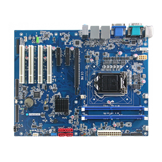
Page 17: Product Overview
User’s Manual 2.1 Product Overview EAX-H110KP User’s Manual 17... -
Page 18: Jumper And Connector List
SYSFAN1 4 x 1 wafer, pitch 2.54mm function supported) 3 x 1 wafer, pitch 2.54mm SYSFAN2 System fan connector 2 JFP1 Miscellaneous setting connector 5 x 2 header, pitch 2.54 mm DIMM1/3 288-pin DDR4 DIMM socket 18 EAX-H110KP User’s Manual... - Page 19 2 x 4 wafer, pitch 4.20mm ATX12V1 Power connector SATA1~4 Serial ATA connector 1~4 HDMI1 HDMI connector DP connector VGA connector VGA1 S/PDIF connector 1 x 4 header, pitch 2.54mm JSPDIF1 SMBus connector 5 x 1 header, pitch 2.54mm JSMB1 EAX-H110KP User’s Manual 19...
-
Page 20: Setting Jumpers & Connectors
EAX-H110KP User’s Manual 2.3 Setting Jumpers & Connectors 2.3.1 Serial port 1 pin9 signal select (JRI1) Ring* +12V * Default 2.3.2 Serial port 2 pin9 signal select (JRI2) Ring* +12V * Default 20 EAX-H110KP User’s Manual... -
Page 21: Serial Port 3 Pin9 Signal Select (Jri3)
User’s Manual 2.3.3 Serial port 3 pin9 signal select (JRI3) Ring* +12V * Default 2.3.4 AT/ATX Power Mode Select (JATATX1) * Default EAX-H110KP User’s Manual 21... -
Page 22: Clear Cmos (Jcmos1)
EAX-H110KP User’s Manual 2.3.5 Clear CMOS (JCMOS1) Protect* Clear CMOS * Default 2.3.6 COM2 RS485/422 connector (JCOM2B) Signal PIN PIN Signal 485TX- 422RX- 485TX+ 422RX+ 22 EAX-H110KP User’s Manual... -
Page 23: Com2 Rs485/422 Connector (Jcom3B)
User’s Manual 2.3.7 COM2 RS485/422 connector (JCOM3B) Signal PIN PIN Signal 485TX-_C 422RX-_C 485TX+_C 422RX+_C 2.3.8 Serial Port2 connector (JCOM2A) Signal PIN PIN Signal NRXDB NDCDB# NDTRB# NTXDB NDSRB# NCTSB# NRTSB# JNRIB# EAX-H110KP User’s Manual 23... -
Page 24: Serial Port 3/4/5/6 Connector (Jcom3-6)
Signal PIN PIN Signal NDCDC# NRXDC NTXDC NDTRC# NDSRC# NRTSC# NCTSC# JNRIC# NDCDD# NRXDD NTXDD NDTRD# NDSRD# NRTSD# NCTSD# NRID# NDCDE# NRXDE NTXDE NDTRE# NDSRE# NRTSE# NCTSE# NRIE# NDCDF# NRXDF NTXDF NDTRF# NDSRF# NRTSF# NCTSF# NRIF# 24 EAX-H110KP User’s Manual... -
Page 25: Serial Port 3/4/5/6 Connector (Jcom7-10)
Signal PIN PIN Signal COM_DCD#_7 COM_RXD_7 COM_TXD_7 COM_DTR#_7 COM_DSR#_7 COM_RTS#_7 COM_CTS#_7 COM_RI#_7 COM_DCD#_8 COM_RXD_8 COM_TXD_8 COM_DTR#_8 COM_DSR#_8 COM_RTS#_8 COM_CTS#_8 COM_RI#_8 COM_DCD#_9 COM_RXD_9 COM_TXD_9 COM_DTR#_9 COM_DSR#_9 COM_RTS#_9 COM_CTS#_9 COM_RI#_9 COM_DCD#_10 COM_RXD_10 COM_TXD_10 COM_DTR#_10 COM_DSR#_10 COM_RTS#_10 COM_CTS#_10 COM_RI#_10 EAX-H110KP User’s Manual 25... -
Page 26: General Purpose I/O Connector (Jdio1)
EAX-H110KP User’s Manual 2.3.11 General purpose I/O connector (JDIO1) Signal PIN PIN Signal SMB_CLK_9555 17 18 SMB_DATA_9555 2.3.12 ATX Power connector (ATXPWR1) Signal PIN PIN Signal +3.3V +3.3V -12V +3.3V PSON# ATX_PWRGD +5VSB +12V +12V +3.3V 26 EAX-H110KP User’s Manual... -
Page 27: Power Connector (Atx12V1)
User’s Manual 2.3.13 Power connector (ATX12V1) Signal PIN PIN Signal +12V +12V +12V +12V 2.3.14 SMBus connector (JSMB1) Signal SMB_CLK_MAIN SMB_DATA_MAIN SMB_ALERT#_MAIN +3.3V EAX-H110KP User’s Manual 27... -
Page 28: Usb Connector 2 (Jusb2)
EAX-H110KP User’s Manual 2.3.15 USB connector 2 (JUSB2) Signal USBVCC5 USB_R_DN5 USB_R_DP5 2.3.16 USB connector 4 (JUSB4) Signal Signal USBVCC_9A USBVCC_9A USB_R_DN10 USB_R_DN9 USB_R_DP10 USB_R_DP9 28 EAX-H110KP User’s Manual... -
Page 29: Battery Connector (Jbat1)
User’s Manual 2.3.17 Battery connector (JBAT1) Signal +3.3V 2.3.18 LPC connector (JLPC1) Signal PIN PIN Signal LPC_AD0_R +3.3V LPC_AD1_R BUF_PLT_RST# LPC_AD2_R LPC_FRAME#_R LPC_AD3_R LPC_CLK LPC_SERIRQ_R EAX-H110KP User’s Manual 29... -
Page 30: Spi Connector (Jspi1)
EAX-H110KP User’s Manual 2.3.19 SPI connector (JSPI1) Signal PIN PIN Signal +3.3V SSPI_CS0#_R SSPI_SCLK_R SSPI_SO_R SSPI_SI_R SSPI_HOLD#0 2.3.20 Speaker connector (JSPK1) Signal LSPK+ LSPK- RSPK+ RSPK - 30 EAX-H110KP User’s Manual... -
Page 31: Audio Connector (Jaudio)
User’s Manual 2.3.21 Audio connector (JAUDIO) Signal PIN PIN Signal MIC2_L MIC2_R ACZ_DET#_R LINE2_RIN MIC2_JD LINE2_LIN LINE_JD 2.3.22 Miscellaneous setting connector (JFP1) Signal PIN PIN Signal HDD_LED+ PWR_LED+ HDD_LED- PWE_LED- RSET_BTN# PWRBTN# EAX-H110KP User’s Manual 31... -
Page 32: Cpu Fan Connector (Cpufan1)
EAX-H110KP User’s Manual 2.3.23 CPU fan connector (CPUFAN1) Signal CPUFANOUT CPUFANIN +12V 2.3.24 System fan connector 1 (SYSFAN1) Signal SYSFANOUT1 SYSFANIN1 +12V 32 EAX-H110KP User’s Manual... -
Page 33: System Fan Connector 2 (Sysfan2)
User’s Manual 2.3.25 System fan connector 2 (SYSFAN2) Signal SYS_FAN_IN_2 +12V 2.3.26 PS/2 keyboard & mouse connector (JKBMS1) Signal KBCK KBDT MSDT +5V_KBMS MSCK EAX-H110KP User’s Manual 33... -
Page 34: S/Pdif Connector (Jspdif1)
EAX-H110KP User’s Manual 2.3.27 S/PDIF connector (JSPDIF1) Signal SPDIF_O 2.3.28 External Speaker connector (JBZ1) Signal HDA_SPKR 34 EAX-H110KP User’s Manual... -
Page 35: Lpt Connector (Jlpt1)
PTD1 PT_PAR_INIT# PTD2 PT_SLIN# PTD3 PTD4 PTD5 PTD6 PTD7 ACK# BUSY SLCT 2.3.30 Auxiliary Panel connector (JAUXP1) Signal PIN PIN Signal SMB_CLK_MAIN CASEOPEN# ERROR_LED SMB_DATA_MAIN ERROR_LED# FRONT_LAN1_ACT 13 FRONT_LAN1_LINK100# 16 FRONT_LAN1_LINK1000# FRONT_LAN2_ACT 17 FRONT_LAN2_LINK100# 20 FRONT_LAN2_LINK1000# EAX-H110KP User’s Manual 35... -
Page 36: Bios Setup
EAX-H110KP User’s Manual 3.BIOS Setup 36 EAX-H110KP User’s Manual... -
Page 37: Introduction
If you do not press the keys at the correct time and the system does not boot, an error message will be displayed and you will again be asked to. Press F1 to Continue, DEL to enter SETUP EAX-H110KP User’s Manual 37... -
Page 38: Using Setup
Note: Some of the navigation keys differ from one screen to another. To Display a Sub Menu Use the arrow keys to move the cursor to the sub menu you want. Then press <Enter>. A “” pointer marks all sub menus. 38 EAX-H110KP User’s Manual... -
Page 39: Getting Help
BIOS Vendor and your systems manufacturer to provide the absolute maximum performance and reliability. Even a seemingly small change to the chipset setup has the potential for causing you to use the override. EAX-H110KP User’s Manual 39... -
Page 40: Bios Setup
<Enter> to accept and enter the sub-menu. 3.6.1 Main Menu This section allows you to record some basic hardware configurations in your computer and set the system clock. 40 EAX-H110KP User’s Manual... -
Page 41: System Language
Note: The BIOS setup screens shown in this chapter are for reference purposes only, and may not exactly match what you see on your screen. Visit the Avalue website (www.avalue.com.tw) to download the latest product and BIOS information. EAX-H110KP User’s Manual 41... -
Page 42: Advanced Menu
3.6.2.1 Trusted Computing Item Options Description Enables or Disables BIOS support for security Disabled device. O.S. will not show Security Device. Security Device Support Enabled[Default], TCG EFI protocol and INT1A interface will not be available. 42 EAX-H110KP User’s Manual... -
Page 43: Apci Settings
Enable/Disable system waked up by Ring Disabled Wake Up by Ring signal from S3(Sleep). S4(Hibernate) and Enabled[Default], S5(Soft Off) States. Enable/Disable USB Power delivery in S3 USB Standby Power Disabled (Sleep), S4 (Hibernate) and S5 (Soft Off) Delivery Enabled[Default], States. EAX-H110KP User’s Manual 43... -
Page 44: S5 Rtc Wake Settings
Dynamic_Time:System will wake on the Dynamic Time current time + Increase minute(s). Item Options Description Disabled[Default], Enable or disable System wake on RTC alarm Wake system from S5 Fixed Time event. Fixed Time:System will wake on the 44 EAX-H110KP User’s Manual... -
Page 45: Super Io Configuration
+ Increase minute(s). Wake up minute increase 3.6.2.4 Super IO Configuration You can use this item to set up or change the Super IO configuration for serial ports. Please refer to 3.6.2.6.1~ 3.6.2.6.7 for more information. EAX-H110KP User’s Manual 45... - Page 46 Set Parameters of Serial Port 7 (COMG). Serial Port 8 Configuration Set Parameters of Serial Port 8 (COMH). Serial Port 9 Configuration Set Parameters of Serial Port 9 (COMI). Serial Port 10 Configuration Set Parameters of Serial Port 10 (COMJ). 46 EAX-H110KP User’s Manual...
-
Page 47: Serial Port 1 Configuration
Enable or Disable Serial Port (COM). Enabled[Default] 3.6.2.4.2 Serial Port 2 Configuration Item Option Description Disabled, Serial Port Enable or Disable Serial Port (COM). Enabled[Default] UART 232 422 485 RS232[Default] Set COM Port as RS232, RS422 or RS485 mode. EAX-H110KP User’s Manual 47... -
Page 48: Serial Port 3 Configuration
RS422 RS485 3.6.2.4.3 Serial Port 3 Configuration Item Option Description Disabled, Serial Port Enable or Disable Serial Port (COM). Enabled[Default] RS232[Default] UART 232 422 485 RS422 Set COM Port as RS232, RS422 or RS485 mode. RS485 48 EAX-H110KP User’s Manual... -
Page 49: Serial Port 4 Configuration
3.6.2.4.4 Serial Port 4 Configuration Item Option Description Disabled, Serial Port Enable or Disable Serial Port (COM). Enabled[Default] 3.6.2.4.5 Serial Port 5 Configuration Item Option Description Disabled, Serial Port Enable or Disable Serial Port (COM). Enabled[Default] EAX-H110KP User’s Manual 49... -
Page 50: Serial Port 6 Configuration
EAX-H110KP User’s Manual 3.6.2.4.6 Serial Port 6 Configuration Item Option Description Disabled, Serial Port Enable or Disable Serial Port (COM). Enabled[Default] 3.6.2.4.7 Parallel Port Configuration Item Option Description Disabled, Parallel Port Enable or Disable Parallel Port (LPT/LPTE). Enabled[Default] 50 EAX-H110KP User’s Manual... -
Page 51: Serial Port 7 Configuration
3.6.2.4.8 Serial Port 7 Configuration Item Option Description Disabled, Serial Port Enable or Disable Serial Port (COM). Enabled[Default] 3.6.2.4.9 Serial Port 8 Configuration Item Option Description Disabled, Serial Port Enable or Disable Serial Port (COM). Enabled[Default] EAX-H110KP User’s Manual 51... -
Page 52: Serial Port 9 Configuration
3.6.2.4.10 Serial Port 9 Configuration Item Option Description Disabled, Serial Port Enable or Disable Serial Port (COM). Enabled[Default] 3.6.2.4.11 Serial Port 10 Configuration Item Option Description Disabled, Serial Port Enable or Disable Serial Port (COM). Enabled[Default] 52 EAX-H110KP User’s Manual... -
Page 53: Nct6106D H/W Monitor
3.6.2.5.1 Smart Fan Mode Configuration Item Option Description Manual Mode Mode 01 Mode 02 Avalue Smart Fan Mode Select: Mode 01 to Mode CPU Fan Mode Mode 03 20 Or Manual(No Smart Fan) Mode 04 Mode 05 Mode 06 EAX-H110KP User’s Manual 53... - Page 54 Avalue Smart Fan Mode Select: Mode 01 to Mode SYS FAN Mode Mode 10 20 Or Manual(No Smart Fan) Mode 11 Mode 12 Mode 13 Mode 14 Mode 15 Mode 16 Mode 17 Mode 18 Mode 19 Mode 20 54 EAX-H110KP User’s Manual...
-
Page 55: Serial Port Console Redirection
3.6.2.6 Serial Port Console Redirection Item Options Description Disabled[Default], Console Redirection Console Redirection Enable or Disable. Enabled Legacy Console Redirection Legacy Console Redirection Settings Settings Disabled[Default], Console Redirection Console Redirection Enable or Disable. Enabled 3.6.2.6.1 COM1 EAX-H110KP User’s Manual 55... - Page 56 With this mode enabled only text will be sent. Recorder Mode Enabled This is to capture Terminal data. Disabled[Default] Enables or disables extended terminal Resolution 100×31 Enabled resolution. VT100[Default] LINUX XTERMR6 Putty KeyPad Select FunctionKey and KeyPad on Putty. ESCN VT400 56 EAX-H110KP User’s Manual...
-
Page 57: Intel Txt Configuration
User’s Manual 3.6.2.7 Intel TXT Configuration 3.6.2.8 Intel RC ACPI Settings Item Option Description Auto[Default] Enabled-OS Controlled ASPM, Native ASPM Enabled Disabled-BIOS Controlled ASPM Disabled EAX-H110KP User’s Manual 57... -
Page 58: Cpu Configuration
Number of cores to enable in each processor Active Processor Cores package. Enabled for Windows XP and Linux(OS Disabled optimized for Hyper-Threading Technology) and Hyper-Threading Enabled[Default], Disabled for other OS (OS not optimized for Hyper-Threading Technology). 58 EAX-H110KP User’s Manual... -
Page 59: Cpu-Power Management Control
Enable or Disable Package C-State UnDemotion. Disabled, 0:Disable;1:Enable;<b>2:Auto</b> Package C-State Un-demotion Enabled (Auto:Enabled for Skylake; Disabled for Auto[Default] Kabylake) Auto[Default] Maximum Package C State Limit Setting. Cpu Package C State Limit Cpu Default Default: Leaves to Factory default EAX-H110KP User’s Manual 59... -
Page 60: Pch-Fw Configuration
EAX-H110KP User’s Manual value.Auto :Initializes to deepest available Package C State Limit. C0/C1 3.6.2.10 PCH-FW Configuration Item Options Description Disabled, When Disabled ME will be put into ME Temporarily ME State Enabled[Default] Disabled Mode. 60 EAX-H110KP User’s Manual... -
Page 61: Firmware Update Configuration
Me FW Image Re-Flash Enable/Disable Me FW Image Re-Flash function. Enabled 3.6.2.11 Network Stack Configuration Item Options Description Disabled[Default] Network Stack Enable/Disable UEFI Network Stack. Enabled Disabled[Default] Ipv4 PXE Support Enable/Disable IPv4 PXE boot support. If disabled, IPv4 Enabled EAX-H110KP User’s Manual 61... -
Page 62: Csm Configuration
Ip6 Configuration Policy Set IP6 Configuration Policy Manual PXE boot wait time Wait time to press ESC key to abort the PXE boot. Media detect count Number of times presence of media will be checked. 3.6.2.12 CSM Configuration 62 EAX-H110KP User’s Manual... -
Page 63: Usb Configuration
Legacy[Default] Do not launch Determines OpROM execution policy for Other PCI devices UEFI devices other than Network, Storage, or Legacy[Default] Video. 3.6.2.13 USB Configuration The USB Configuration menu helps read USB information and configures USB settings. EAX-H110KP User’s Manual 63... - Page 64 Mass storage device emulation type. ‘AUTO’ Auto[Default] Floppy enumerates devices according to their media format. Optical drives are emulated as ‘CDROM’, Mass Storage Devices Forced FDD Hard Disk drives with no media will be emulated according CD-ROM to a drive type. 64 EAX-H110KP User’s Manual...
-
Page 65: Chipset
User’s Manual 3.6.3 Chipset 3.6.3.1 System Agent (SA) Configuration Item Option Description Disabled VT-d VT-d capability. Enabled[Default] EAX-H110KP User’s Manual 65... -
Page 66: Memory Configuration
Item Option Description Auto[Default] IGFX Select which of IGFX/PEG/PCI Graphics device should Primary Display be Primary Display Or select SG for Switchable Gfx. Auto[Default] Disabled Internal Graphics Keep IGFX enabled based on the setup options. Enabled 66 EAX-H110KP User’s Manual... -
Page 67: Dmi/Opi Configuration
User’s Manual 3.6.3.1.3 DMI/OPI Configuration 3.6.3.1.4 PEG Port Configuration Item Option Description Disabled Enable Root Port Enabled Enable or Disable the Root Port. Auto[Default] Auto[Default] Gen1 Max Link Speed Configure PEG 0:1:0 Max Speed. Gen2 Gen3 EAX-H110KP User’s Manual 67... -
Page 68: Peg Port Feature Configuration
Program PCIe ASPM after OpROM after OpROM. Disabled: PCIe ASPM will be Enabled programmed before OpROM. 3.6.3.1.4.1 PEG Port Feature Configuration Item Option Description Disabled[Default] Detect Non-Compliance PCI Express Device Detect Non-Compliance Device Enabled in PEG. 68 EAX-H110KP User’s Manual... -
Page 69: Pch-Io Configuration
User’s Manual 3.6.3.2 PCH-IO Configuration Item Option Description Enabled[Default] Enable/Disable onboard I219 Network Interface PCH LAN Controller Disabled Controller. Enabled[Default] Enable/Disable integrated LAN(I219) to wake the Wake on LAN Enable Disabled system. 3.6.3.2.1 PCI Express Configuration EAX-H110KP User’s Manual 69... -
Page 70: Pci-E #5: Pci-E X4 Slot#1
L0sL1 links to L0s State AUTO – BIOS auto ASPM configure DISABLE – Disables ASPM Disabled[Default] Disabled[Default] L1.1 L1 Substates PCI Express L1 Substates settings. L1.2 L1.1 & L1.2 Gen1 PCIe Speed Configure PCIe Speed. Gen2[Default] 70 EAX-H110KP User’s Manual... -
Page 71: Extra Options
Device. If enable, it will take more time at Enabled POST time. Prefetchable Memory Range for this Root Prefetchable Memory Bridge. Reseved Memory Alignment Reseved Memory Alignment(0-31 bits) Prefetchable Memory Alignment Prefetchable Memory Alignment (0-31 bits) EAX-H110KP User’s Manual 71... -
Page 72: Pci-E #7: Pci-E X4 Slot#2(Only X2 Width)
L0s State AUTO – BIOS auto ASPM configure DISABLE – Disables ASPM. L0sL1 Auto Disabled[Default] L1.1 L1 Substates PCI Express L1 Substates settings. L1.2 L1.1 & L1.2 Gen1 PCIe Speed Configure PCIe Speed. Gen2 [Default] 72 EAX-H110KP User’s Manual... -
Page 73: Extra Options
Device. If enable, it will take more time at Enabled POST time. Prefetchable Memory Range for this Root Prefetchable Memory Bridge. Reseved Memory Alignment Reseved Memory Alignment(0-31 bits) Prefetchable Memory Alignment Prefetchable Memory Alignment (0-31 bits) EAX-H110KP User’s Manual 73... -
Page 74: Pci-E Port 9:Lan(I211At)
PCI-E Port 9:LAN(I211AT) Item Option Description Enabled[Default], PCI-E Port 9:LAN2(I211AT) Control the PCI Express Root Port. Disabled 3.6.3.2.1.4 PCI-E Port 10:PCI-to-PCI Bridge Item Option Description Disabled PCI-E Port10:PCIe-to-PCI Bridge Control the PCI Express Root Port. Enabled[Default], 74 EAX-H110KP User’s Manual... -
Page 75: Sata And Rst Configuration
State Drive or Hard Disk Drive. Disabled SATA4 Port Enable or Disable SATA Port. Enabled[Default], Hard Disk Drive[Default] Identify the SATA port is connected to Solid SATA Device Type Solid State Drive State Drive or Hard Disk Drive. EAX-H110KP User’s Manual 75... -
Page 76: Hd Audio Configuration
HDA will be unconditionally disabled Enabled = HDA will HD Audio Enabled, be unconditionally enabled Auto = HDA will be enabled if Auto[Default] present, disabled otherwise. 11 dB 14 dB[Default], Amplifier Gain Select Amplifier Gain(dB). 19 dB 25 dB 76 EAX-H110KP User’s Manual... -
Page 77: Security
User’s Manual 3.6.4 Security Administrator Password Set setup Administrator Password User Password Set User Password 3.6.4.1 Secure Boot EAX-H110KP User’s Manual 77... -
Page 78: Key Management
OEM-defined factory default Secure Boot keys Allow the image to run in Secure Boot mode. Enroll SHA256 Hash Enroll Efi Image certificate of a PE image into Authorized Signature Database(db) Restore DB defaults Restore DB variable to factory defaults 78 EAX-H110KP User’s Manual... -
Page 79: Boot
Number of seconds to wait for setup activation Setup Prompt Timeout key. 65535(0xFFFF) means indefinite waiting. On[Default] Bootup NumLock State Select the keyboard NumLock state Disabled[Default] Quiet Boot Enables or disables Quiet Boot option Enabled Boot Option #1 Sets the system boot order. EAX-H110KP User’s Manual 79... -
Page 80: Save And Exit
Reset the system setup without saving any changes. 3.6.6.3 Restore Defaults Restore/Load Default values for all the setup options. 3.6.6.4 Launch EFI Shell from filesystem device Attempts to Launch EFI Shell application (Shell.efi) from one of the available filesystem devices. 80 EAX-H110KP User’s Manual... -
Page 81: Drivers Installation
User’s Manual 4. Drivers Installation Note: Installation procedures and screen shots in this section are for your reference and may not be exactly the same as shown on your screen. EAX-H110KP User’s Manual 81... -
Page 82: Install Chipset Driver
Windows 10 operation system. If the warning message appears while the installation process, click Continue to go on. Step 3. Click Install. Step1. Click Next. Step 4. Complete setup. Step 2. Click Accept. 82 EAX-H110KP User’s Manual... -
Page 83: Install Vga Driver
Windows 10 operation system. Step 3. Click Next. Step 1. Click Next to continue installation. Step 4. Click Next. Step 2. Step 5. Click Finish to complete setup. Click Yes to accept license agreement. EAX-H110KP User’s Manual 83... -
Page 84: Install Sol Driver
Note: The installation procedures and screen shots in this section are based on Windows 10 operation system. Step 3. Click Next Step 4. Click Finish to complete the setup Step 1. Click Next to continue setup. Step 2. Click Next. 84 EAX-H110KP User’s Manual... -
Page 85: Install Audio Driver (For Realtek Alc892 Hd Audio)
Windows 10 operation system. If the warning message appears while the installation process, click Continue to go on. Step2. installing Step1. Click Next to Install. Step 3. Select Finish to complete Installation. EAX-H110KP User’s Manual 85... -
Page 86: Install Lan Driver
Note: The installation procedures and screen shots in this section are based on Windows 10 operation system. Step 3. Click Next. Step 1. Click Install Drivers and Software. Step 4. Click Next. Step 2. Click Next. Step 5. Click Install. 86 EAX-H110KP User’s Manual... - Page 87 Note: The installation procedures and screen shots in this section are based on Windows 10 operation system. Step 2. Click Next. Step 1. Click Next to continue installation. Step 3. Click Next. EAX-H110KP User’s Manual 87...
- Page 88 EAX-H110KP User’s Manual Step 4. Click Next. Step 6. Click Finish to complete setup. Step 5. Click Next. 88 EAX-H110KP User’s Manual...
- Page 89 User’s Manual 5. Mechanical Drawing EAX-H110KP User’s Manual 89...
- Page 90 EAX-H110KP User’s Manual Unit: mm 90 EAX-H110KP User’s Manual...
- Page 91 User’s Manual Unit: mm EAX-H110KP User’s Manual 91...
Need help?
Do you have a question about the EAX-H110KP and is the answer not in the manual?
Questions and answers