Table of Contents

Related Manuals for Avalue Technology EPI-QM87


Summary of Contents for Avalue Technology EPI-QM87
- Page 1 EPI-QM87 Intel® 4 Generation Core™ i7/i5/i3 Processor EPIC Module with Intel® QM87 Chipset User’s manual Ed – 26 February 2014 Copyright Notice Copyright 2014 Avalue Technology Inc., ALL RIGHTS RESERVED. Part No. E2047382800R...
- Page 2 Disclaimer Avalue Technology Inc. reserves the right to make changes, without notice, to any product, including circuits and/or software described or contained in this manual in order to improve design and/or performance. Avalue Technology assumes no responsibility or liability for the...
- Page 3 Applications that are described in this manual are for illustration purposes only. Avalue Technology Inc. makes no representation or warranty that such application will be suitable for the specified use without further testing or modification.
- Page 4 (such as your sales receipt) in a shippable container. A product returned without proof of the purchase date is not eligible for warranty service. 5. Write the RMA number visibly on the outside of the package and ship it prepaid to your dealer. 4 EPI-QM87 User’s Manual...
-
Page 5: Table Of Contents
EC SMB Reserve connector (JECDEG) ................. 30 2.4.17 5VSB connector in ATX (PWR_SB) ..................30 2.4.18 IrDA connector (JIR) ........................ 31 2.4.19 SPI connector (JSPI) ....................... 31 2.4.20 LVDS connector (JLVDS) ......................32 2.4.21 Touch panel connector (JTOUCH) ..................33 EPI-QM87 User’s Manual 5... - Page 6 3.6.2.13 Intel RC Drivers Version Detail ................56 3.6.3 Chipset ........................... 56 3.6.3.1 PCH-IO Configuration ..................57 3.6.3.1.1 PCI Express Configuration ................58 3.6.3.1.1.1 PCI Express Root Port 1 ................... 58 3.6.3.1.2 USB Configuration ................... 59 6 EPI-QM87 User’s Manual...
-
Page 7: User's Manual Epi-Qm87 User's Manual
Install USB 3.0 Driver (For Intel QM87) ............... 71 Install Display Driver (For Intel QM87) ..............72 Install Audio Driver (For Realtek ALC892) ............73 Install Ethernet Driver (For Intel I210AT and I217LM) ......... 74 5. Mechanical Drawing ....................75 EPI-QM87 User’s Manual 7... -
Page 8: Getting Started
Before you begin installing your single board, please make sure that the following materials have been shipped: 1 x EPI-QM87 EPIC Module 1 x Quick Installation Guide for EPI-QM87 1 x DVD-ROM contains the followings: — User’s Manual (this manual in PDF file) —... -
Page 9: Document Amendment History
User’s Manual 1.3 Document Amendment History Revision Date Comment February 2014 Initial Release EPI-QM87 User’s Manual 9... -
Page 10: Manual Objectives
We strongly recommend that you study this manual carefully before attempting to interface with EPI-QM87 series or change the standard configurations. Whilst all the necessary information is available in this manual we would recommend that unless you are confident, you contact your supplier for guidance. -
Page 11: System Specifications
Realtek ALC892 HD codec support 5.1 channel Audio Interface Mic-In, Line-In and Line-Out Built-in Touch screen (optional) Chipset PenMount 6000 Touch screen With 9-pin 2.0mm Box Header (can be selected to support 4/5/8 wire touch screen) interface EPI-QM87 User’s Manual 11... - Page 12 Single power ATX Support S0, S3, S4, S5 ACPI ACPI 3.0 Compliant Operating Temp. 0°C ~60°C Storage Temp. -40°C ~75°C Operating Humidity 0%~90% relative humidity, non-condensing Size (L x W) 4.5" x 6.5" (115mm x 165mm) Weight 0.41 lbs (0.18 Kg) 12 EPI-QM87 User’s Manual...
-
Page 13: Architecture Overview - Block Diagram
User’s Manual 1.6 Architecture Overview – Block Diagram The following block diagram shows the architecture and main components of EPI-QM87. EPI-QM87 User’s Manual 13... -
Page 14: Hardware Configuration
EPI-QM87 2. Hardware Configuration 14 EPI-QM87 User’s Manual... -
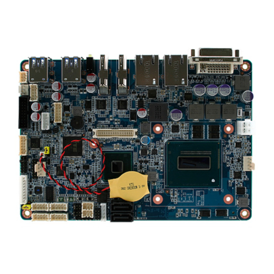
Page 15: Product Overview
User’s Manual 2.1 Product Overview EPI-QM87 User’s Manual 15... - Page 16 EPI-QM87 16 EPI-QM87 User’s Manual...
-
Page 17: Installation Procedure
Note: Make sure the heat sink and the CPU top surface are in total contact to avoid CPU overheating problem that would cause the system to hang or unstable EPI-QM87 User’s Manual 17... -
Page 18: Main Memory
EPI-QM87 2.2.1 Main Memory EPI-QM87 provides one 204-pin DDR3L SODIMM socket, supports up to 8GB 1.35V DDR3L 1333/1600 SDRAM. SODIMM (Rear side) Make sure to unplug the power supply before adding or removing SODIMMs or other system components. Failure to do so may cause severe damage to both the board and the components. - Page 19 (2) Static electricity can damage the electronic components of the computer or optional boards. Before starting these procedures, ensure that you are discharged of static electricity by touching a grounded metal object briefly. EPI-QM87 User’s Manual 19...
-
Page 20: Jumper And Connector List
Serial port 1 - Ring, +5V, +12V power JRI1/2 3 x 2 header, pitch 2.00mm selector Touch panel connector 3 x 1 header, pitch 2.54mm JTOUCH_SEL LCD Backlight brightness adjustment 3 x 1 header, pitch 2.00mm 20 EPI-QM87 User’s Manual... - Page 21 SATA2 System Fan connector 4 x 1 wafer, pitch 2.54mm SYS_FAN USB1 USB 3.0 connector 0 & 1 USB2 USB 3.0 connector 2 & 3 JECDEG EC SMB Reserve connector 2 x 1 header, pitch 2.00mm EPI-QM87 User’s Manual 21...
-
Page 22: Setting Jumpers & Connectors
EPI-QM87 2.4 Setting Jumpers & Connectors 2.4.1 Clear CMOS (JBAT) RTC Working* RTC Reset *Default 2.4.2 Serial port 1/2 - Ring, +5V, +12V power selector (JRI1/2) Ring* +12V JRI2 JRI1 * Default 22 EPI-QM87 User’s Manual... -
Page 23: At/Atx Mode Selector, Front Panel & Led Settings (Jfp)
AT/ATX mode selector, Front panel & LED settings (JFP) Signal PWBT 1, 2 RST# 3, 4 PWR-LED 5, 6 *Default HDD-LED 7, 8 Short: AT MODE 9, 10 Open: ATX MODE CASE_OPEN# 11, 12 2.4.4 Touch panel connector (JTOUCH_SEL) 4/ 8W * Default EPI-QM87 User’s Manual 23... -
Page 24: Lcd Backlight Brightness Adjustment (Jvr)
EPI-QM87 2.4.5 LCD Backlight brightness adjustment (JVR) PWM mode* DC Mode * Default 2.4.6 Battery connector (BAT) Signal +3.3V 24 EPI-QM87 User’s Manual... -
Page 25: Audio Connector (Jaudio)
User’s Manual 2.4.7 Audio connector (JAUDIO) Signal Signal FRONT-L-OUT FRONT-R-OUT LINE1-L-IN LINE1-R-IN MIC1-L-IN MIC1-R-IN LINE1_JD FRONT_JD MIC1_JD 2.4.7.1 Signal Description – Audio connector (JAUDIO) Signal Signal Description LINE1_JD Jack detection for line1 MIC1_JD Jack detection for mic1 EPI-QM87 User’s Manual 25... -
Page 26: Cpu Fan Connector (Cpu_Fan)
EPI-QM87 2.4.8 CPU fan connector (CPU_FAN) Signal +12V EC_TACH0 FAN_PWM0 2.4.9 System fan connector (SYS_FAN) Signal +12V EC_TACH1 FAN_PWM1 26 EPI-QM87 User’s Manual... -
Page 27: Ps/2 Keyboard & Mouse Connector (Jkbms)
User’s Manual 2.4.10 PS/2 keyboard & mouse connector (JKBMS) Signal Signal KBCK KBDT KBVCC MSCK MSDT 2.4.11 SATA power connector (SATA_PWR) Signal EPI-QM87 User’s Manual 27... -
Page 28: Serial Port 1/ 2 Connector (Jcom1/ Jcom2)
TXD_2 DTR#_2 DCD#_2 RXD_2 2.4.13 Serial port 3/ 4 connector (JCOM3/ JCOM4) JCOM3 Signal Signal NRIC# NRTSC# NCTSC# NDSRC# NTXDC NDTRC# NDCDC# NRXDC JCOM4 Signal Signal NRID# NRTSD# NCTSD# JCOM4 JCOM3 NDSRD# NTXDD NDTRD# NDCDD# NRXDD 28 EPI-QM87 User’s Manual... -
Page 29: Serial Port 1/2 Rs-422-485 Mode (J422_1 / J422_2)
COM1/2 in BIOS setting 2.4.15 LCD Inverter Connector (JBKL) Signal +12V BKLEN VBRIGHT 2.4.15.1 Signal Description – LCD Inverter Connector (JBKL) Signal Signal Description Vadj = 0.75V ~ 4.25V (Recommended: 4.7KΩ, >1/16W) VBRIGHT BKLEN LCD backlight ON/OFF control signal EPI-QM87 User’s Manual 29... -
Page 30: Ec Smb Reserve Connector (Jecdeg)
EPI-QM87 2.4.16 EC SMB Reserve connector (JECDEG) Signal EC_SMCLK_DEBUG EC_SMDAT_DEBUG 2.4.17 5VSB connector in ATX (PWR_SB) Signal PSON_ATX# +ATX5VSB 30 EPI-QM87 User’s Manual... -
Page 31: Irda Connector (Jir)
User’s Manual 2.4.18 IrDA connector (JIR) Signal IR_TX IR_RX 2.4.19 SPI connector (JSPI) Signal Signal +3.3V SPI_CS0# SPI_CLK SPI_SO SPI-SI HOLD# SPI_WP# EPI-QM87 User’s Manual 31... -
Page 32: Lvds Connector (Jlvds)
EPI-QM87 2.4.20 LVDS connector (JLVDS) Signal PIN PIN Signal +12V +12V LVDS_CLK2_N LVDS_CLK1_N LVDS_CLK2_P LVDS_CLK1_P LVDS_DATA7_N LVDS_DATA6_N LVDS_DATA7_P LVDS_DATA6_P LVDS_DATA5_N LVDS_DATA4_N LVDS_DATA5_P LVDS_DATA4_P LVDS_DATA3_N LVDS_DATA2_N LVDS_DATA3_P LVDS_DATA2_P LVDS_DATA1_N LVDS_DATA0_N LVDS_DATA1_P LVDS_DATA0_P +3.3V +3.3V 32 EPI-QM87 User’s Manual... -
Page 33: Touch Panel Connector (Jtouch)
User’s Manual 2.4.21 Touch panel connector (JTOUCH) Signal SENSE TOUCH_GND 4-WIRE 5-WIRE 8-WIRE Right Sense Left Sense Bottom Sense Sense Top Sense Right Right Excite Left Left Excite Bottom Bottom Excite Top Excite EPI-QM87 User’s Manual 33... -
Page 34: General Purpose I/O Connector (Jdio)
EPI-QM87 2.4.22 General purpose I/O connector (JDIO) Signal PIN PIN Signal DIO_GP10 DIO_GP20 DIO_GP11 DIO_GP21 DIO_GP12 DIO_GP22 DIO_GP13 DIO_GP23 SMB_DATA_9555 10 SMB_CLK_9555 2.4.23 Power connector (PWR) Signal Signal +DC_IN +DC_IN 34 EPI-QM87 User’s Manual... -
Page 35: Usb 2.0 Connector (Jusb1)
USB_PN_Z_13 USB_PP_Z_12 USB_PP_Z_13 Note: Wrong USB cable configuration with USB devices might damage USB devices 2.4.25 USB 2.0 connector (JUSB2) Signal Signal USBVCC4 USB3_RXN5_L USBVCC5 USB3_RXP5_L USB3_RXN6_L USB3_RXP6_L USB3_TXN5_L USB3_TXP5_L USB3_TXN6_L USB3_TXP6_L USB_PN_Z_8 USB_PP_Z_8 USB_PN_Z_10 USB_PP_Z_10 EPI-QM87 User’s Manual 35... -
Page 36: Bios Setup
EPI-QM87 3. BIOS Setup 36 EPI-QM87 User’s Manual... -
Page 37: Introduction
OFF then ON or pressing the "RESET" button on the system case. You may also restart by simultaneously pressing <Ctrl>, <Alt>, and <Delete> keys. Remove all storage can also enter the BIOS Setup Utility. EPI-QM87 User’s Manual 37... -
Page 38: Using Setup
Note: Some of the navigation keys differ from one screen to another. To Display a Sub Menu Use the arrow keys to move the cursor to the sub menu you want. Then press <Enter>. A “” pointer marks all sub menus. 38 EPI-QM87 User’s Manual... -
Page 39: Getting Help
BIOS Vendor and your systems manufacturer to provide the absolute maximum performance and reliability. Even a seemingly small change to the chipset setup has the potential for causing you to use the override. EPI-QM87 User’s Manual 39... -
Page 40: Bios Setup
Note: The BIOS setup screens shown in this chapter are for reference purposes only, and may not exactly match what you see on your screen. Visit the Avalue website (www.avalue.com.tw) to download the latest product and BIOS information. 40 EPI-QM87 User’s Manual... -
Page 41: Advanced Menu
User’s Manual 3.6.2 Advanced Menu This section allows you to configure your CPU and other system devices for basic operation through the following sub-menus. 3.6.2.1 APCI Settings EPI-QM87 User’s Manual 41... -
Page 42: S5 Rtc Wake Settings
Select PWRON After PWR-Fail. Former-Sts 3.6.2.2 S5 RTC Wake Settings Item Options Description Enable or disable System wake on alarm Disabled[Default], Wake system with Fixed Time event. When enabled, System will wake on the Enabled hr::min::sec specified. 42 EPI-QM87 User’s Manual... -
Page 43: Trusted Computing
O.S will not show Security Device. Security Device Support Enabled TCG EFI protocol and INT1A interface will not be available. 3.6.2.4 CPU Configuration Use the CPU configuration menu to view detailed CPU specification and configure the CPU. EPI-QM87 User’s Manual 43... - Page 44 Configure Short/Long latency for C6. Long Disabled CPU C7 Report CPU C7 Enable/Disable CPU C7 report to OS. CPU C7s[Default] Short C7 Latency Configure Short/Long latency for C7. Long[Default] C0/C1 Package C State limit Package C State limit. 44 EPI-QM87 User’s Manual...
-
Page 45: Sata Configuration
RAID Default[Default] Indicates the maximum speed the SATA Gen1 SATA Controller Speed Gen2 controller can support. Gen3 Enabled[Default] Port 0/1/4 Enable or Disable SATA Port. Disabled Enabled Hut Plug Designates this port as Hot Pluggable. Disabled[Default] EPI-QM87 User’s Manual 45... -
Page 46: Software Feature Mask Configuration
3.6.2.5.1 Software Feature Mask Configuration Item Option Description Enabled[Default] Enable or disable RAID0 RAID0 Disabled feature. Enabled[Default] Enable or disable RAID1 RAID1 Disabled feature. Enabled[Default] Enable or disable RAID10 RAID10 Disabled feature. 3.6.2.6 Intel(R) Rapid Start Technology Configuration 46 EPI-QM87 User’s Manual... -
Page 47: Pch-Fw Configuration
Enable or disable Intel® Rapid Intel® Rapid Start Technology Disabled[Default] Start Technology. 3.6.2.7 PCH-FW Configuration Item Options Description Disabled[Default] MDES BIOS Status Code Enable/Disable MDES BIOS Status Code. Enabled Firmware Update Configuration Configure Management Engine Technology Parameters. EPI-QM87 User’s Manual 47... -
Page 48: Firmware Update Configuration
EPI-QM87 3.6.2.7.1 Firmware Update Configuration Item Options Description Enable/Disable Me FW Image Re-Flash Disabled[Default] Me FW Image Re-Flash function. Enabled 3.6.2.8 AMT Configuration Intel AMT allows hardware-based remote management, security, power-management, and remote-configuration features. 48 EPI-QM87 User’s Manual... -
Page 49: Usb Configuration
Enable/Disable USB Mass Storage Driver USB Mass Storage Driver Support Disabled Support. Mass storage device emulation type. ‘AUTO’ Auto[Default] Mass Storage Devices Floppy enumerates devices according to their media Forced FDD format. Optical drives are emulated as EPI-QM87 User’s Manual 49... -
Page 50: Hardware Monitor
The following system temperature, fan speed and voltage are monitored. Temperature: System Temperature CPU Thermistor Temperature Fan Speed: System Fan Speed CPU Fan speed Voltage: VCORE +12V +5VSB AVCC 3VCC VSB3 VBAT 50 EPI-QM87 User’s Manual... -
Page 51: Super Io Configuration
User’s Manual 3.6.2.11 Super IO Configuration You can use this item to set up or change the Super IO configuration. Please refer to 3.6.2.11.1~4 for more information. 3.6.2.11.1 Serial Port 1 Configuration EPI-QM87 User’s Manual 51... -
Page 52: Serial Port 2 Configuration
IO=2F8h; IRQ=3 IO=3F8h; IRQ=3,4,5,6,7,9,10,11,12 Select an optimal setting for Change Settings IO=2F8h; IRQ=3,4,5,6,7,9,10,11,12 super IO device. IO=3E8h; IRQ=3,4,5,6,7,9,10,11,12 IO=2E8h; IRQ=3,4,5,6,7,9,10,11,12 Change the Serial Port Normal[Default] Device Mode mode. Select <High Speed> High Speed or <Normal mode> mode. 52 EPI-QM87 User’s Manual... -
Page 53: Serial Port 3 Configuration
IO=2F0h; IRQ=3,4,5,6,7,10,11,12 IO=2E0h; IRQ=3,4,5,6,7,10,11,12 Serial Port Function Mode[Default] IR Mode,Pusle 1.6us, Full Duplex Change the Serial Port Device Mode IR Mode,Pusle 1.6us, Half Duplex mode. IR Mode,Pusle 3/16Bit Timer, Full Duplex IR Mode,Pusle 3/16Bit Timer, Half Duplex EPI-QM87 User’s Manual 53... -
Page 54: Serial Port 4 Configuration
3.6.2.11.4 Serial Port 4 Configuration Item Option Description Enabled[Default], Enable or Disable Serial Port Serial Port Disabled (COM) Auto[Default] IO=2E8h; IRQ=10 IO=3E8h; IRQ=3,4,5,6,7,10,11,12 Select an optimal setting for Change Settings IO=2E8h; IRQ=3,4,5,6,7,10,11,12 super IO device. IO=2F0h; IRQ=3,4,5,6,7,10,11,12 IO=2E0h; IRQ=3,4,5,6,7,10,11,12 54 EPI-QM87 User’s Manual... -
Page 55: Network Stack
User’s Manual 3.6.2.12 Network Stack Item Option Description Enabled Network stack Enable/Disable UEFI network stack. Disabled[Default] Enable Ipv4/6 PXE Boot Support. If Enabled Ipv4/6 PXE Support disabled IPV4/6 PXE boot option will not Disabled[Default] be created. EPI-QM87 User’s Manual 55... -
Page 56: Intel Rc Drivers Version Detail
EPI-QM87 3.6.2.13 Intel RC Drivers Version Detail 3.6.3 Chipset 56 EPI-QM87 User’s Manual... -
Page 57: Pch-Io Configuration
PCH Azalia Configuration PCH Azalia Configuration settings. Disabled PCH LAN Controller Enable or disable onboard NIC. Enabled[Default] Disabled 1-2 Seconds Select a minimum assertion width SLP_S4 Assertion Width 2-3 Seconds of the SLP_S4# signal. 3-4 Seconds 4-5 Seconds[Default] EPI-QM87 User’s Manual 57... -
Page 58: Pci Express Configuration
PCI Express Root Port 1 PCI Express Root Port 1 Settings. PCI Express Root Port 6 PCI Express Root Port 6 Settings. PCI Express Root Port 7 PCI Express Root Port 7 Settings. 3.6.3.1.1.1 PCI Express Root Port 1 58 EPI-QM87 User’s Manual... -
Page 59: Usb Configuration
Select PCI Express port speed. Gen2 3.6.3.1.2 USB Configuration Item Option Description Smart Auto[Default] Mode of operation of xHCI xHCI Mode Disabled controller. Disabled[Default] Control each of the USB ports USB Ports Per-Port Disable Control Enabled (0~13) disabling. EPI-QM87 User’s Manual 59... -
Page 60: Pch Azalia Configuration
Control Detection of the Azalia device. Deisabled = Azalia will be Disabled unconditionally disabled Enabled = Azalia will be unconditionally Azalia Enabled Enabled Auto = Azalia will be enabled if present, disabled Auto[Default] otherwise. 3.6.3.2 System Agent (SA) Configuration 60 EPI-QM87 User’s Manual... -
Page 61: Graphics Configuration
User’s Manual 3.6.3.2.1 Graphics Configuration 3.6.3.2.1.1 Graphics Configuration Item Option Description Graphics turbo IMON current Graphics Turbo IMON Current 14 ~31[Default] values (14 -31) EPI-QM87 User’s Manual 61... -
Page 62: Lcd Control
Secondary Primary IGFX Boot Display LVDS boot display selection will appear based on your selection. VGA modes will be HDMI-2 supported only on primary display. Panel Scaling Auto[Default] Select the LCD panel scaling option used 62 EPI-QM87 User’s Manual... - Page 63 Select LVDS back light PWM duty. 100% 200 Hz[Default] 300 Hz 400 Hz 500 Hz 700 Hz LVDS Back Light PWM 1 kHz Select LVDS back light PWM Frequency. Frequency 2 kHz 3 kHz 5 kHz 10 kHz 20 kHz EPI-QM87 User’s Manual 63...
-
Page 64: Memory Configuration
EPI-QM87 3.6.3.2.2 Memory Configuration 3.6.4 Boot Item Option Description Number of seconds to wait for setup activation key. Setup Prompt Timeout 1~ 65535 65535(0xFFFF) means indefinite waiting. Bootup NumLock State On[Default] Select the Keyboard NumLock 64 EPI-QM87 User’s Manual... -
Page 65: Csm Parameters
Controls the execution of UEFI Launch Storage OpROM policy UEFI only and Legacy Storage OpROM. Legacy only[Default] Do not launch Controls the execution of UEFI Launch Video OpROM policy UEFI only and Legacy Video OpROM. Legacy only[Default] EPI-QM87 User’s Manual 65... -
Page 66: Security
For PCI devices other than UEFI OpROM[Default] Other PCI device ROM priority Network, Mass storage or Video Legacy OpROM defines which OpROM to launch. 3.6.5 Security Administrator Password Set setup Administrator Password User Password Set User Password 66 EPI-QM87 User’s Manual... -
Page 67: Save And Exit
The setup program then exits and reboots the controller. 3.6.6.3 Restore Defaults This option restores all BIOS settings to the factory default. This option is useful if the controller exhibits unpredictable behavior due to an incorrect or inappropriate BIOS setting. EPI-QM87 User’s Manual 67... -
Page 68: Drivers Installation
EPI-QM87 4. Drivers Installation Note: Installation procedures and screen shots in this section are for your reference and may not be exactly the same as shown on your screen. 68 EPI-QM87 User’s Manual... -
Page 69: Install Chipset Driver (For Intel Qm87)
If the warning message appears while the installation Step 3. Click Next. process, click Continue to go on. Step1. Click Next. Step 4. Click Next. Step 2. Click Yes. Step 5. Click Finish to complete setup. EPI-QM87 User’s Manual 69... -
Page 70: Install Me Driver (For Intel Qm87)
Step 3. Click Next to proceed setup. appears while the installation process, click Continue to go on. Step1. Click Next to start installation. Step 4. Click Finish to complete setup. Step 2. Click Yes to accept license agreement. 70 EPI-QM87 User’s Manual... -
Page 71: Install Usb 3.0 Driver (For Intel Qm87)
Step 3. Click Next to continue installation. process, click Continue to go on. Step 4. Click Next to continue installation. Step1. Click Next to start installation. Step 2. Click Yes. Step 5. Click Finish to complete setup. EPI-QM87 User’s Manual 71... -
Page 72: Install Display Driver (For Intel Qm87)
Windows XP operation system. Step 3. Click Next. Step 4. Click Next. Step 1. Click Next to continue installation. Step 5. Click Finish to complete setup. Step 2. Click Yes to accept license agreement. 72 EPI-QM87 User’s Manual... -
Page 73: Install Audio Driver (For Realtek Alc892)
\Driver_Audio\Realtek\ALC892\EPI-QM87_Audio. Note: The installation procedures and screen shots in this section are based on Windows 2000 operation system. Step 1. Click Next to continue setup. Step 2. Click Finish to complete the setup. EPI-QM87 User’s Manual 73... -
Page 74: Install Ethernet Driver (For Intel I210At And I217Lm)
Step 3. Click Install to proceed. screen shots in this section are based on Windows XP operation system. Step 4. Click Finish to complete the setup. Step 1. Click Next. Step 2. Click Next to accept license agreement. 74 EPI-QM87 User’s Manual... -
Page 75: Mechanical Drawing
User’s Manual 5. Mechanical Drawing EPI-QM87 User’s Manual 75... - Page 76 EPI-QM87 Unit: mm 76 EPI-QM87 User’s Manual...
- Page 77 User’s Manual Unit: mm EPI-QM87 User’s Manual 77...
Need help?
Do you have a question about the EPI-QM87 and is the answer not in the manual?
Questions and answers