
Related Manuals for Lantech LES-2400-RPS


Summary of Contents for Lantech LES-2400-RPS
-
Page 1: User Manual
Lantech LES-2400-RPS 3-slot Modularized Fast Ethernet L2 + 2 Gigabit Copper / Mini-GBIC Combo Managed Switch User Manual v1.2 Apr-2011... -
Page 3: Table Of Contents
Contents 1. INTRODUCTION ...................... 1 Features ........................1 Software Features ......................2 Package Contents ......................5 Ethernet Switching Technology ..................6 2. HARDWARE DESCRIPTION ................... 7 Physical Dimensions ..................... 7 Front Panel ........................7 LED Indicators ......................8 Rear Panel ........................9 Desktop Installation .................... - Page 4 DHCP Server ......................23 TFTP ........................... 27 System Event Log....................... 30 SNTP Configuration ....................36 IP Security ........................40 User Authentication ....................42 Advanced Configuration ..................... 43 Port Statistics ......................45 Port Control ........................ 46 Port Trunk ........................48 Port Mirroring ......................52 Rate Limiting .......................
-
Page 5: Introduction
1. Introduction The 3-slot Modularized Fast Ethernet L2 plus + 2 Gigabit Copper / Mini-GBIC Combo Managed Switch is a modular Ethernet switch that can be used to build high-performance switched workgroup networks. This switch is a store-and-forward device that offers low latency for high-speed networking. The Switch is targeted at workgroup, department or backbone computing environments. -
Page 6: Software Features
Backpressure for half duplex High back-plane bandwidth 8.8Gbps Supports IEEE802.3ad Port trunk with LACP Broadcast storm filter supported IGMP supports for Multi Media application Supports IEEE 802.1p class of service Port security supported ... - Page 7 RFC 1215 Trap MIB RFC 1643 Ethernet like RMON1 Private MIB Cold/warm start trap, link down/link up trap, authorization SNMP Trap fail trap, fan fail trap. power event trap Supports IEEE802.3ad with LACP function. Up to 13 trunk Port Trunk groups, trunk member up to 4 ports and include 2 uplink ports IEEE802.1d spanning tree, IEEE 802.1w Rapid Spanning...
- Page 8 Per port support ingress rate limiting and egress rate shaping control. Bandwidth Control The rate limiting and rate shaping can be setting from 0~100Mbps Support IEEE802.1x User-Authentication and can report to RADIUS server. 802.1x Reject Authentication Accept Authorize ...
-
Page 9: Package Contents
Package Contents Unpack the contents of the 3 -slot intelligent chassis switch and verify them against the checklist below. 3-slot intelligent chassis switch Power Cord Four Rubber Feet RS-232 cable Rack-mounted kit User Manual (CD-ROM) 3-slot intelligent chassis switch Four Rubber Feet RS-232 Cable... -
Page 10: Ethernet Switching Technology
Ethernet Switching Technology Ethernet Switching Technology dramatically boosted the total bandwidth of a network, eliminated congestion problems inherent with CSMA/CD (Carrier Sense multiple access with Collision Detection) protocol, and greatly reduced unnecessary transmissions. This revolutionized networking. First, by allowing two-way simultaneous transmissions over the same port (Full-duplex) essentially doubled the bandwidth. -
Page 11: Hardware Description
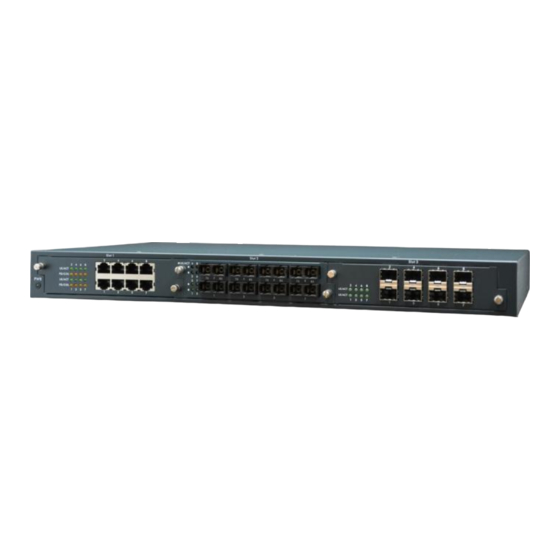
2. Hardware Description This Section mainly describes the hardware of the 3-slot intelligent chassis switch, and gives a physical and functional overview of the switch. Physical Dimensions The 3-slot intelligent chassis switch physical dimensions are 440mm(W) x 44mm(H) x 280mm(D). Front Panel The Front Panel of the 3-slot intelligent chassis switch supports up to 4 kinds of module. -
Page 12: Led Indicators
LED Indicators The LED Indicators gives real-time information of systematic operation status. The following tables describe definitions for LED indicators. Status Description Green The port is connecting with the device. LK/ACT Blinks The port is receiving or transmitting data. No device attached. Yellow The port is operating in Full-duplex mode. -
Page 13: Rear Panel
Rear Panel Equipped with a 3-pronged power plug for AC power input and a 14-pin dual-row connector for DC power input, the Ethernet switch allows users to supply AC power in the range of 100 to 240V/50-60Hz or DC power in the range of 12 to 48V for redundant supplying purposes. -
Page 14: Desktop Installation
Desktop Installation Set the Switch on a sufficiently large flat space with a power outlet nearby. The surface where you put your Switch should be clean, smooth, level and sturdy. Make sure there is enough clearance around the Switch to allow attachment of cables, power cord and allow air circulation. - Page 15 with the smaller bracket screws. Then attach the remaining bracket to the other side of the Switch. Attach mounting brackets with screws After attaching both mounting brackets, position the switch in the rack by lining up the holes in the brackets with the appropriate holes on the rack. Secure the Switch to the rack with a screwdriver and the rack-mounting screws.
-
Page 16: Power On
Power On Connect the 3-prong AC power cord or the 14-pin 2-row DC power cable to the power socket at the rear panel of the Ethernet switch. The Ethernet switch can work with AC power in the voltage range of 100-240V/50~60Hz or 12-48VDC. The AC and DC inputs can be used for redundant power supply. -
Page 17: Network Application
3. Network Application This section provides you a few samples of network topology in which the Switch is used. In general, the 3-slot intelligent chassis switch is designed as a segment switch. That is, with its large MAC address table (8K-entry) and high performance, it is ideal for interconnecting networking segments. -
Page 18: Connecting To The Switch
Connecting to the Switch The Console port is a female DB-9 connector that enables a connection to a PC or terminal for monitoring and configuring the Switch. Use the supplied RS-232 cable with a male DB-9 connector to connect a terminal or PC to the Console port. The Console configuration (out of band) allows you to set Switch for remote terminal as if the console terminal were directly connected to it. -
Page 19: Console Management
4. Console Management Login in the Console Interface When the connection between Switch and PC is ready, turn on the PC and run a terminal emulation program or Hyper Terminal and configure its communication parameters to match the following default characteristics of the console port: Baud Rate: 9600 bps Data Bits: 8 Parity: none... -
Page 20: Module Hot-Swapping
Console login screen Module Hot-Swapping The 3-slot Modularized Fast Ethernet L2 plus + 2 Gigabit Copper / Mini-GBIC Combo Managed Switch supports module hot-swapping. User can insert or pull the module out of the slot without powering down the switch. Once the module is not fully inserted, the LEDs on the module panel will all light on at the same time. -
Page 21: Web-Based Management
5. Web-Based Management This section introduces the configuration and functions of the Web-Based management. About Web-based Management Inside the CPU board of the switch, there exists an embedded HTML web site residing in flash memory. It offers advanced management features and allow users to manage the switch from anywhere on the network through a standard browser such as Microsoft Internet Explorer. -
Page 22: System Login
System Login Launch the Internet Explorer on the PC Key in ―http:// ―+‖ the IP address of the switch‖, and then Press ―Enter‖. The login screen will appear right after Key in the user name and password. The default user name and password are the same as ―root‖... -
Page 23: Main Interface
Main interface Main interface... -
Page 24: System Information
System Information Here you can view the system information and assign the system name and location to make this switch more easily identified on your network. System Name: Assign the name of the switch. The maximum length is 64 bytes. ... -
Page 25: Ip Configuration
IP Configuration DHCP Client: Enable or disable the DHCP client function. When the DHCP Client function is enabled, the industrial switch will be assigned an IP address from the network DHCP server. The default IP address will be replaced by the assigned IP address on DHCP server. - Page 26 IP configuration interface...
-
Page 27: Dhcp Server
DHCP Server DHCP is the abbreviation of Dynamic Host Configuration Protocol that is a protocol for assigning dynamic IP addresses to devices on a network. With dynamic addressing, a device can have a different IP address every time it connects to the network. In some systems, the device's IP address can even change while it is still connected. - Page 28 System configuration DHCP Server: This pull-down menu allows you to configure the switch to be the DHCP server on your local network. Low IP Address: Type in an IP address as the beginning of a range of the dynamic IP address.
- Page 29 Client Entries When the DHCP Server function is enabled, the system will collect the DHCP client information including the assigned IP address, the MAC address of the client device, the IP assigning type, states and lease time. DHCP Client Entries interface...
- Page 30 Port and IP Bindings As the figure shown below, the switch will assign the IP address to the connected client according to the Port-IP binding table. The user is allowed to fill each port with one particular IP address. When the device is connecting to the port and asks for IP assigning, the system will assign the IP address bound with the port to the device.
-
Page 31: Tftp
TFTP It provides the functions allowing the user to update the switch firmware via the Trivial File Transfer Protocol (TFTP) server. Before updating, make sure the TFTP server is ready and the firmware image is located on the TFTP server. Update Firmware ... - Page 32 Restore Configuration You can restore a previous backup configuration from the TFTP server to recover the settings. Before doing that, you must locate the image file on the TFTP server first for the switch to download back the flash image. ...
- Page 33 Backup Configuration You can back up the current configuration from flash ROM to the TFTP server for the purpose of recovering the configuration later. It helps you avoid wasting time on configuring the settings by backing up the entire configuration. ...
-
Page 34: System Event Log
System Event Log This page allows the user to decide whether to send the system event log, and select the mode which the system event log will be sent to client only, server only, or both client and server. What kind of event log will be issued to the client/server depends on the selection on the Event Configuration tab. - Page 35 Syslog Configuration interface...
- Page 36 System Event Log—SMTP Configuration Simple Mail Transfer Protocol (SMTP) is the standard for email transmissions across the network. You can configure the SMTP server IP address, sender mail account, password, and the recipient email account to which the e-mail alert will send. Besides, this page provides the authentication mechanism including authentication steps through which the client effectively logs in to the SMTP server during the process of sending e-mail alert.
- Page 37 SMTP Configuration interface...
- Page 38 System Event Log—Event Configuration The checkboxes and pull-down menus are not available unless the Syslog Client Mode on the Syslog Configuration tab and the E-mail Alert on the SMTP Configuration tab are enabled first. This tab mainly controls whether an event notification is to be sent to the Syslog/SMTP server.
- Page 39 Event Configuration interface...
-
Page 40: Sntp Configuration
SNTP Configuration SNTP (Simple Network Time Protocol) is a simplified version of NTP which is an Internet protocol used to synchronize the clocks of computers with some time reference. Because time usually just advances, the time on different node stations might be different. - Page 41 CST - Central Standard -6 hours 6 am MDT - Mountain Daylight MST - Mountain Standard -7 hours 5 am PDT - Pacific Daylight PST - Pacific Standard -8 hours 4 am ADT - Alaskan Daylight ALA - Alaskan Standard -9 hours 3 am HAW - Hawaiian...
- Page 42 JST - Japan Standard, +9 hours 9 pm USSR Zone 8 EAST - East Australian Standard GST +10 hours 10 pm Guam Standard, USSR Zone 9 IDLE - International Date Line NZST - New Zealand +12 hours Midnight Standard NZT - New Zealand ...
- Page 43 SNTP Configuration interface...
-
Page 44: Ip Security
IP Security IP security function allows the user to assign up to 10 specific IP addresses that have permission to manage the switch through the http and telnet services for securing switch management. The purpose of giving permission to limited IP addresses is to allow only the authorized personnel/device to do the management task on the switch. - Page 45 IP Security interface...
-
Page 46: User Authentication
User Authentication The User Authentication interface allows users to configure login user account and password for security reasons. User Name: The user account is root by default. Type in the User Name field with a new name as you wish. ... -
Page 47: Advanced Configuration
Advanced Configuration Broadcast Storm Filter This tab allows users to enable the broadcast storm filter for the specific packet type. Tick the checkboxes respectively to enable the filters. Flooded Unicast/Multicast Packets: When this check box is ticked, the switch will filter the packet type of Flooded Unicast/Multicast. - Page 48 Aging Time This tab is used to assign the aging time of the MAC table. Aging Time of MAC Table: Set the aging time on OFF, 150 sec, 300 sec, or 600 sec. When MAC table is not used within the aging time, the MAC address table will then be cleared.
-
Page 49: Port Statistics
Port Statistics The following chart provides the current statistics information which displays the real-time packet transfer states for each port. The user might use the information to plan and implement the network, or check and find the problem when the collision or heavy traffic occurs. -
Page 50: Port Control
Port Control In Port Control you can configure the settings of each port to control the connection parameters. Port: Scroll up/down the scroll bar and click on the port number to choose a particular port to be configured. State: Enable/disable the port. - Page 51 Port Control interface...
-
Page 52: Port Trunk
Port Trunk Port trunking is the combination of several ports or network cables to expand the connection speed beyond the limits of any one single port or network cable. Link Aggregation Control Protocol (LACP), which is a protocol running on layer 2, provides a standardized means in accordance with IEEE 802.3ad to bundle several physical ports together to form a single logical channel. - Page 53 The system allows a maximum of four ports to be aggregated in a trunk group. Having configured the parameters above, highlight the ports in the right list box to join the trunk group. Click the Add button and the ports highlighted in the right list box will be shifted to the left list box.
- Page 54 Aggregator Information When you have set the LACP aggregator, you will see the related information here. Port Trunk – Aggregator Information interface...
- Page 55 State Activity Having configured the LACP aggregator on the Aggregator Setting tab, you may want to change the state activity for the members of the LACP trunk group. You can tick/untick the checkbox beside the state label. If you remove the tick mark of the corresponding port and click the Apply button, the port state activity will change to Passive.
-
Page 56: Port Mirroring
Port Mirroring Port Mirroring is a method for monitoring of network traffic on switched networks. Traffic through ports can be monitored by one specific port, which means traffic going in or out the monitored (source) ports will be duplicated into the analysis (mirroring) port. -
Page 57: Rate Limiting
Rate Limiting You can respectively configure the ingress/egress rate for each port. Rate Limiting interface All the ports support packet ingress and egress rate control. InRate: Enter the port effective ingress rate (The default value is ―0‖). OutRate: Enter the port effective egress rate (The default value is ―0‖). ... -
Page 58: Vlan Configuration
VLAN Configuration A Virtual LAN (VLAN) is a logical network grouping that limits the broadcast domain, which allows you to isolate network traffic. Therefore only the members of the same VLAN will receive traffic from the ones among the same VLAN. Basically, creating a VLAN on a switch is logically equivalent of reconnecting a group of network devices to another Layer 2 switch;... - Page 59 VLAN – Port Based interface Click Add to create a new VLAN group (The VLAN groups can be up to 64). VLAN—Port Based Add interface Enter the group name and VLAN ID. Select the port number available in the left list...
- Page 60 box, and click the Add button to move the highlighted ports to the right list box. Or you can select any of the ports listed in the right field and click Remove to remove port(s) from the VLAN. When finished, click Apply to have the VLAN configuration take effect. ...
- Page 61 802.1Q VLAN When the VLAN operation mode is set on 802.1Q, all ports on the switch belong to the default VLAN of VID 1, which means they logically are regarded as members of the same broadcast domain. The valid VLAN ID is in the range of number between 1 and 4094. The amount of VLAN groups is up to 256 including the default VLAN that cannot be deleted.
- Page 62 After you have configured the three parameters, click the Apply button right beneath this area to finish creating an 802.1Q VLAN. 802.1q VLAN interface On the 802.1Q Configuration tab, click the Port pull-down menu to select a port you want to configure within the VLAN.
- Page 63 untagged frame gets into the access port, the switch inserts a four-byte tag in the frame. The contents of the last 12-bit of the tag is the untagged VID. When this frame is sent out through any of the access ports of the same PVID, the switch will remove the tag from the frame to recover it to what it was.
- Page 64 Access Link and Hybrid Link. Assign a number in the range between 1 and 4094. Tagged Vid: This field is available when the Link Type pull-down menu is set on Trunk Link and Hybrid Link. Assign a number in the range between 1 and 4094. ...
- Page 65 Group Configuration interface When finished, click Apply to have the modification take effect.
-
Page 66: Rapid Spanning Tree
Rapid Spanning Tree The Rapid Spanning Tree Protocol (RSTP) is an evolution of the Spanning Tree Protocol providing for faster spanning tree convergence after a topology change. The system also supports STP and will auto-detect the connected device running STP or RSTP. - Page 67 Bridge ID: This field displays the bridge ID by showing the MAC address of this switch. Root Priority: This field displays the numerical value indicating bridge priority of the switch. Generally, the switch with the lowest numerical value in the network is set as the root bridge.
- Page 68 Port Configuration This tab offers the interface for RSTP port configuration where you can assign parameters to each port. The rapid spanning tree protocol will have the port with the higher priority in forwarding state and block other ports to make certain that there is no loop in the LAN.
- Page 69 RSTP Port Configuration interface...
-
Page 70: Pro-Ring System
Pro-Ring System X-Ring provides a faster redundant recovery than Spanning Tree topology. The action is similar to STP or RSTP, but the algorithms not the same. In the X-Ring topology, every switch should enable X-Ring function and assign two member ports in the ring. Only one switch in the X-Ring group would be set as a master switch that would be blocked, called backup port, and another port is called working port. - Page 71 Enable Coupling Ring: To enable the coupling ring function. Marking the check box to enable the coupling ring function. Coupling port: Assign the member port. Control port: Set the switch as the master switch in the coupling ring. ...
-
Page 72: Snmp Configuration
SNMP Configuration Simple Network Management Protocol (SNMP) is the protocol developed to manage nodes (servers, workstations, routers, switches and hubs etc.) on an IP network. SNMP enables network administrators to manage network performance, find and solve network problems, and plan for network growth. Network management systems (NMS) learn of problems by receiving traps or change notices from network devices implementing SNMP. - Page 73 SNMP System Configuration interface...
- Page 74 Trap Configuration A trap manager is a management station that receives trap messages generated by the switch. If no trap manager is defined, no traps will be issued. To define a management station as a trap manager, assign an IP address, enter the SNMP community strings, and select the SNMP trap version.
- Page 75 SNMPV3 Configuration This tab allows users to configure the SNMPv3 settings for communications via SNMPv3. Context Table Configure the SNMPv3 context table. Assign the context name in the field. Click Apply to add the context name added or changed. User Table Configure the SNMPv3 user table.
- Page 76 SNMP V3 configuration interface Access Table Configure the SNMPv3 access table.
- Page 77 Context Prefix: In this filed type in the prefix letters of the context name that is assigned in the context table. Group Name: Type in the group name that is assigned in the group table. Security Level: Select a radio button to determine which security level is assigned to the group.
-
Page 78: Qos Configuration
QoS Configuration You can configure Qos mode, 802.1p priority [7-0] setting, Static Port Ingress Priority setting and TOS setting. Qos Mode: Click the pull-down menu to select the Qos policy rule. Disable QoS Priority: The default status of Qos Priority is disabled. ... - Page 79 QoS Configuration interface...
-
Page 80: Igmp Configuration
IGMP Configuration IGMP is the protocol used by IPv4 systems to report their IP multicast group memberships to neighboring multicast routers. IGMPv3 adds support for "source filtering", that is, the ability for a system to report interest in receiving packets only from specific source addresses, or from all but specific source addresses, sent to a particular multicast address. - Page 81 IGMP Configuration interface...
-
Page 82: Lldp
LLDP Link Layer Discovery Protocol (LLDP), a one way protocol, specified in the IEEE 802.1AB standard allows stations attached to the same IEEE 802 LAN to advertise their information to neighbors and store the information received from adjacent stations. Receivers on the same physical LAN will store the information distributed via LLDP in a standard Management Information Base (MIB) where the information can be accessed by a Network Management System (NMS) using a protocol like the Simple Network Management Protocol (SNMP). -
Page 83: 802.1X/Radius
802.1x/Radius 802.1x is an IEEE authentication specification that allows a client to connect to a wireless access point or wired switch but prevents the client from gaining access to the Internet until it provides authority, like a user name and password that are verified by a separate server. - Page 84 Port Configuration You can configure 802.1x authentication state for each port. The State provides Disable, Accept, Reject and Authorize. Use ―Space‖ key to change the state value. Reject: The specified port is required to be held in the unauthorized state. ...
- Page 85 Misc Configuration Quiet Period: Set the period during which the port doesn‘t try to acquire a supplicant. TX Period: Set the period the port waits for retransmitting the next EAPOL PDU during an authentication session. Supplicant Timeout: Set the period of time the switch waits for a supplicant response to an EAP request.
-
Page 86: Mac Address Table
MAC Address Table The MAC Address Table interface allows users to configure static MAC addresses, MAC filtering, multicast filtering and provides information of all MAC addresses on each port. Static MAC Address You can add a static MAC address that remains in the switch's address table regardless of whether the device is physically connected to the switch. - Page 87 MAC Filtering By filtering MAC address, the switch can easily filter pre-configured MAC addresses and reduce the un-safety. You can add or delete filtering MAC addresses. MAC Filtering interface MAC Address: Enter the MAC address to be filtered. VLAN ID: Type in the VLAN group ID the MAC address belongs.
- Page 88 All MAC Addresses This tab displays all MAC address entries learned or set. All MAC Address interface Port No: Click the pull-down menu to select a particular port to show its information. Current MAC Address: Information of the selected port will be displayed in this field.
- Page 89 Multicast Filtering Similar to broadcasts, multicasts are sent to all end stations on a LAN or VLAN. Multicasting filtering is the function which end stations can receive the multicast traffic if the connected ports had been included in the specific multicast groups. With multicast filtering, network devices only forward multicast traffic to the ports that are connected to the registered end stations.
-
Page 90: Access Control List
Access Control List The switch provides a 256-entry access control list (ACL) to check IPv4/non-IPv4 addresses and TCP/UDP port numbers of packets. Group Id: Type in the Group ID from 1 to 255 for the access control list being configured. - Page 91 Access Control List interface...
-
Page 92: Factory Default
Factory Default Click the Reset button to reset the switch back to factory defaults. Before resetting, you can tick the checkboxes to keep the current IP address and user name/password. Factory Default interface... -
Page 93: Save Configuration
Save Configuration Save all changes you have made in the system. To ensure the configurations you have made will be implemented the next time you power on the switch, remember to click the Save button to save the all configurations into the flash memory. Save Configuration interface... -
Page 94: System Reboot
System Reboot Reboot the switch under software control. Click the Reboot button to restart the system. System Reboot interface... -
Page 95: Troubleshooting
6. Troubleshooting This section is intended to help you solve the most common problems on the 3-slot intelligent chassis switch. Incorrect Connections The switch port can auto-detect straight or crossover cable when you link switch with other Ethernet devices. The RJ-45 connector should use correct UTP or STP cable; 10/100Mbps ports use 2-pair twisted cable and Gigabit 1000T ports use 4-pair twisted cable. -
Page 96: Diagnosing Led Indicators
Diagnosing LED Indicators The Switch can be easily monitored through panel indicators to assist in identifying problems, which describes common problems you may encounter and where you can find possible solutions. IF the power indicator does turn on when the power cord is plugged in, you may have a problem with power outlet, or power cord. -
Page 97: Technical Specifications
7. Technical Specifications This section provides the specifications of the 3-slot intelligent chassis switch as the table shown below. IEEE802.3 10BASE-T IEEE802.3u 100BASE-TX/100BASE-FX IEEE802.3z Gigabit SX/LX IEE802.3ab Gigabit 1000T IEEE802.3x Flow Control and Back pressure Standard IEEE802.3ad Port trunk with LACP IEEE802.1d Spanning tree protocol IEEE802.1w Rapid Spanning tree protocol IEEE802.1p Class of service... - Page 98 (Yellow) MINI GBIC: Link/Activity(Green), 1000Mbps (Green) RS-232 console: 1 x DB-9 female 10/100TX module: 8 x RJ-45 100FX (Multi /Single Mode) module: 8 x SC Connector 100SFP module: 8 x SFP Gigabit Copper + Mini-GBIC Combo: 2 x RJ-45 + 2 x Mini-GBIC ...
- Page 99 Redundant Power: DC 12 ~ 48V Ventilation 2 x DC cooling fans with auto-detect function -0 ℃ ~45 ℃ , 5%~95%RH Operating Temp. -40 ℃ ~70 ℃ , 5% ~ 95% RH Storage Temp. FCC Class A, CE Safety UL, cUL, CE/EN60950-1...
Need help?
Do you have a question about the LES-2400-RPS and is the answer not in the manual?
Questions and answers