Table of Contents
Advertisement
Quick Links
Advertisement
Table of Contents

Subscribe to Our Youtube Channel
Related Manuals for Lantech LGS-2404


Summary of Contents for Lantech LGS-2404
- Page 1 4 10/100/1000TX plus 4 Mini GBIC Managed Switch MODEL: LGS-2404 User Manual...
- Page 2 Notice This manual contents are based on the below table listing software kernel version, hardware version, and firmware version. If the switch functions have any different from the manual contents description, please contact the local sale dealer for more information. Firmware Version V1.03 Kernel Version...
-
Page 3: Fcc Warning
FCC Warning This Equipment has been tested and found to comply with the limits for a Class-A digital device, pursuant to Part 15 of the FCC rules. These limits are designed to provide reasonable protection against harmful interference in a residential installation. This equipment generates uses and can radiate radio frequency energy and, if not installed and used in accordance with the instructions, may cause harmful interference to radio communications. -
Page 4: Table Of Contents
Content FCC Warning....................... iii CE Mark Warning ......................iii Introduction........................1 Features ........................1 Software Feature ......................2 Package Contents ......................5 Hardware Description..................... 6 Physical Dimension ......................6 Front Panel ........................6 LED Indicators ......................7 Rear Panel........................7 Desktop Installation ......................8 Power On........................8 Network Application ....................... 9 Desktop Application ......................9 Segment Application.....................9 Console Management.................... - Page 5 TFTP Commands Set...................32 SystemLog, SMTP and Event Commands Set..........32 SNTP Commands Set ..................34 X-ring Commands Set ..................35 Web-Based Management ..................... 37 About Web-based Management .................37 Preparing for Web Management.................37 System Login......................38 System Information.....................39 IP Configuration ......................40 DHCP Server – System configuration.................41 DHCP Client –...
- Page 6 802.1Q Configuration ...................65 Group Configuration ..................65 Rapid Spanning Tree....................67 RSTP System Configuration................67 RSTP Per Port Configuration................68 SNMP Configuration ....................69 System Configuration ..................70 Trap Configuration....................71 SNMPV3 Configuration ..................72 Context Table..................72 User Profile ...................72 Group Table ..................74 Access Table..................74 MIBview Table..................74 QoS Configuration ......................75 QoS Policy and Priority Type................75 Port Base Priority....................76 COS Configuration ....................77...
- Page 7 Faulty or loose cables ................88 Non-standard cables ................88 Improper Network Topologies ...............89 Diagnosing LED Indicators ..................89 Technical Specifications....................90...
- Page 8 viii...
-
Page 9: Introduction
Introduction The 4 10/100/1000TX plus 4 Mini GBIC Managed Switch is a multi-port switch that can be used to build high-performance switched workgroup networks. It provides wire-speed, Gigabit Ethernet switching function that allows high-performance, low-cost connection. The Switches feature a store-and-forward switching and it can auto-learn and store source address on an 8K-entry MAC address table. -
Page 10: Software Feature
IEEE 802.1x user authentication Supports GVRP and MVR function Broadcast storm filter DHCP Client, Relay, Server Per port band width control SNTP and SMTP support Management IP address security MAC address security System log SNMP Trap support Configuration up-load and down-load TFTP firmware update SNMP/Web/ Telnet/CLI/Menu Driven management Software Feature... - Page 11 Support IEEE802.3ad with LACP function. Up Port Trunk with to 4 trunk groups and maximum group LACP member up to 4 ports. IEEE802.1d Spanning tree Spanning Tree IEEE802.1w Rapid spanning tree Port Based VLAN IEEE 802.1Q Tag VLAN (256 entries)/ VLAN ID (Up to 4K, VLAN ID can be assigned from 1 to 4096.) VLAN...
- Page 12 Broadcast/Multicast packet, Broadcast packet only and all of packet. The packet filter rate can be set from 100k to 250Mbps Support IEEE802.1x User-Authentication and can report to RADIUS server. Reject Login Security Accept Authorize Disable Provide IP management security function with IP Security 10 IP addresses.
-
Page 13: Package Contents
Package Contents Unpack the contents of the 4 10/100/1000TX plus 4 Mini GBIC Managed Switch and verify them against the checklist below. 4 10/100/1000TX plus 4 Mini GBIC Managed Switch Power Cord Four Rubber Feet RS-232 cable User Manual 4 10/100/1000TX plus 4 MINI GBIC Four Rubber Pads Power Cord Managed Switch... -
Page 14: Hardware Description
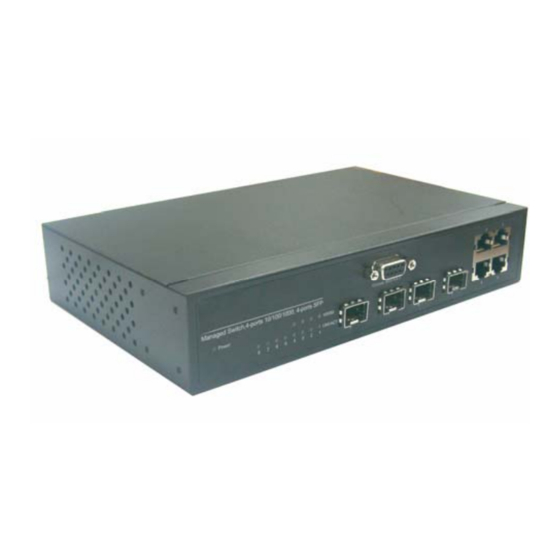
Hardware Description This section mainly describes the hardware of the 4 10/100/1000TX plus 4 Mini GBIC Managed Switch. Physical Dimension The physical dimensions of the 4 10/100/1000TX plus 4 Mini GBIC Managed Switch is 217mm(W) x 140mm(D) x 43mm(H) Front Panel The Front Panel of the 4 10/100/1000TX plus 4 Mini GBIC Managed Switch consists of 4x auto-sensing 10/100/1000Mbps Ethernet RJ-45 ports (automatic MDI/MDIX), 4 Mini GBIC ports, and the LED indicators are also located on the frond panel of the switch. -
Page 15: Led Indicators
LED Indicators LED Indicators The following table provides descriptions of the LED statuses and meaning. They provide a real-time indication of systematic operation status. Status Description Power Green Power On The port is operating at the speed of Green 1000Mbps. 1000M The port is operating at the speed of 100/10Mbps or no device attached... -
Page 16: Desktop Installation
Rear Panel of the 4 10/100/1000TX plus 4 Mini GBIC Managed Switch Desktop Installation Set the switch on a sufficiently large flat space with a power outlet nearby. The surface where you put your Switch should be clean, smooth, level, and sturdy. Make sure there is enough clearance around the Switch to allow attachment of cables, power cord and air circulation. -
Page 17: Network Application
Network Application This section provides you a few samples of network topology in which the switch is used. In general, the 4 10/100/1000TX plus 4 Mini GBIC Managed Switch is designed to be used as a desktop or segment switch. Desktop Application The 4 10/100/1000TX plus 4 Mini GBIC Managed Switch is designed to be a desktop size switch that is an ideal solution for small workgroup. -
Page 18: Console Management
Console Management Connecting to the Console Port Use the supplied RS-232 cable to connect a terminal or PC to the console port. The terminal or PC to be connected must support the terminal emulation program. Connecting the switch to a terminal via RS-232 cable Login in the Console Interface When the connection between Switch and PC is ready, turn on the PC and run a terminal emulation program or Hyper Terminal and configure its communication parameters to... - Page 19 The settings of communication parameters After finished the parameter settings, click “OK“. When the blank screen shows up, press Enter key to bring out the login prompt. Key in the “root“(default value) for the both User name and Password (use Enter key to switch), then press Enter key and the Main Menu of console management appears.
-
Page 20: Cli Management
CLI Management The system supports console management – CLI command. After you log in the system, you will see a command prompt. To enter CLI management interface, enter “enable” command. The following table lists the CLI commands and description. CLI command interface Commands Level Access Exit... - Page 21 The privileged Enter the command is advance enable Enter mode Privileged command switch# disable to Privileged this mode to EXEC while in user exit. • Display advance EXEC mode. function status • Save configures Enter the To exit to configure Use this mode to privileged Global...
-
Page 22: Commands Set List
User EXEC Privileged EXEC Global configuration VLAN database Interface configuration Commands Set List System Commands Set Netstar Commands Level Description Example show config Show switch switch>show config configuration show terminal Show console switch#show terminal information write memory Save user switch#write memory configuration into permanent memory (flash rom) - Page 23 switch no ip dhcp Disable DHCP client switch(config)#no ip dhcp function of switch reload Halt and perform a cold switch(config)#reload restart default Restore to default switch(config)#default admin username Changes a login switch(config)#admin username [Username] username. xxxxxx (maximum 10 words) admin password Specifies a password switch(config)#admin password [Password]...
-
Page 24: Port Commands Set
DHCP server show dhcpserver Show IP-Binding switch#show dhcpserver ip-binding information of DHCP ip-binding server no dhcpserver Disable DHCP server switch(config)#no dhcpserver function security enable Enable IP security switch(config)#security enable function security http Enable IP security of switch(config)#security http HTTP server security telnet Enable IP security of switch(config)#security telnet... - Page 25 Ethernet. Use the speed switch(config)#interface speed [10|100|1000|auto] configuration fastEthernet 2 command to specify switch(config-if)#speed 100 the speed mode of operation for Fast Ethernet., the speed can’t be set to 1000 if the port isn’t a giga port.. no flowcontrol Disable flow control of switch(config-if)#no flowcontrol interface security enable...
- Page 26 broadcast-only limit frame type to fastEthernet 2 “only accept broadcast switch(config-if)#bandwidth type frame” broadcast-only bandwidth in Set interface input switch(config)#interface [Value] bandwidth. Rate fastEthernet 2 Range is from 100 switch(config-if)#bandwidth in 100 kbps to 102400 kbps or to 256000 kbps for giga ports, and zero means no limit.
-
Page 27: Trunk Commands Set
configuration show interface status show interface actual switch(config)#interface status fastEthernet 2 (config-if)#show interface status show interface show interface statistic switch(config)#interface counter accounting fastEthernet 2 (config-if)#show interface accounting no accounting Clear interface switch(config)#interface accounting information fastEthernet 2 switch(config-if)#no accounting Trunk Commands Set Netstar Commands Level Description Example... -
Page 28: Vlan Commands Set
of member ports. aggregator group Assign a static trunk switch(config)#aggregator group [GroupID] [Port-list] group. 1 2-4 nolacp nolacp [GroupID] :1~3 [Port-list]:Member port switch(config)#aggregator group list, This parameter 1 3,1,2 nolacp could be a port range(ex.1-4) or a port list separate by a comma(ex.2, 3, 6) show aggregator Show the information... - Page 29 [Group Name] grpid switch(vlan)#vlan port-based [GroupID] grpname test grpid 2 port 2,3,4 port [PortNumbers] show vlan [GroupID] Show VLAN switch(vlan)#show vlan 23 information show vlan no vlan group Delete port base group switch(vlan)#no vlan group 2 [GroupID] IEEE 802.1Q VLAN Change the name of switch(vlan)#vlan 8021q name vlan 8021q name...
-
Page 30: Spanning Tree Commands Set
vlan 8021q trunk Assign a trunk link for switch(vlan)#vlan 8021q trunk 3 [PortNumber] VLAN by trunk group trunk-link tag 2,3,6,99 trunk-link tag [TaggedVID List] switch(vlan)#vlan 8021q trunk 3 trunk-link tag 3-20 vlan 8021q trunk Assign a hybrid link for switch(vlan)#vlan 8021q trunk 3 [PortNumber] VLAN by trunk group hybrid-link untag 4 tag 3,6,8... - Page 31 the root switch within this interval, it recomputed the Spanning Tree Protocol (STP) topology. spanning-tree Use the spanning-tree switch(config)#spanning-tree hello-time global hello-time [seconds] hello-time 3 configuration command to specify the interval between hello bridge protocol data units (BPDUs). spanning-tree Use the spanning-tree switch(config)#spanning-tree forward-time [seconds]...
- Page 32 Protocol (STP) calculations. In the event of a loop, spanning tree considers the path cost when selecting an interface to place into the forwarding state. stp-path-priority Use the spanning-tree switch(config)#interface [Port Priority] port-priority interface fastEthernet 2 configuration switch(config-if)#stp-path-priority command to configure a port priority that is used when two switches tie for...
-
Page 33: Qos Commands Set
no spanning-tree Disable spanning-tree. switch(config)#no spanning-tree QOS Commands Set Netstar Commands Level Description Example qos policy Select QOS policy switch(config)#qos policy [weighted-fair|strict] scheduling weighted-fair qos prioritytype Setting of QOS priority switch(config)#qos prioritytype [port-based|cos-only|tos type -only|cos-first|tos-first] qos priority portbased Configure Port-based switch(config)#qos priority [Port] Priority... -
Page 34: Mac / Filter Table Commands Set
show igmp multi Displays the details of switch#show igmp multi an IGMP snooping entries. no igmp Disable IGMP switch(config)#no igmp snooping function Disable IGMP query switch#no igmp-query no igmp-query Mac / Filter Table Commands Set Netstar Commands Level Description Example mac-address-table static Configure MAC switch(config)#interface... -
Page 35: Snmp Commands Set
SNMP Commands Set Netstar Commands Level Description Example snmp system-name Set SNMP agent switch(config)#snmp [System Name] system name system-name l2switch snmp system-location Set SNMP agent switch(config)#snmp [System Location] system location system-location lab snmp system-contact Set SNMP agent switch(config)#snmp system contact [System Contact] system-contact where snmp agent-mode... - Page 36 context-name [Context table of SNMPV3 context-name Test group G1 Name ] agent security-level AuthPriv group match-rule Exact views V1 V1 V1 [Group Name ] security-level [NoAuthNoPriv|AuthNoP riv|AuthPriv] match-rule [Exact|Prifix] views [Read View Name] [Write View Name] [Notify View Name] snmpv3 mibview view Configure the mibview switch(config)#snmpv3 mibview [View Name]...
-
Page 37: Port Mirroring Commands Set
security-level [NoAuthNoPriv|AuthNoP riv|AuthPriv] match-rule [Exact|Prifix] views [Read View Name] [Write View Name] [Notify View Name] no snmpv3 mibview Remove specified switch(config)#no snmpv3 view mibview table of mibview view V1 type Excluded [View Name] SNMPV3 agent. sub-oid 1.3.6.1 type [Excluded|Included] sub-oid [OID] Port Mirroring Commands Set Netstar Commands... -
Page 38: 802.1X Commands Set
switch(config-if)#no monitor 802.1x Commands Set Netstar Commands Level Description Example 8021x enable Use the 802.1x global switch(config)# 8021x enable configuration command to enable 802.1x protocols. 8021x system radiusip Use the 802.1x system switch(config)# 8021x system [IP address] radius IP global radiusip 192.168.1.1 configuration command to change... - Page 39 8021x misc quietperiod Use the 802.1x misc switch(config)# 8021x misc [sec.] quiet period global quietperiod 10 configuration command to specify the quiet period value of the switch. 8021x misc txperiod Use the 802.1x misc switch(config)# 8021x misc TX period global [sec.] txperiod 5 configuration...
-
Page 40: Tftp Commands Set
authorize] configuration switch(config-if)#8021x portstate command to set the accept state of the selected port. show 8021x Displays a summary of switch>show 8021x the 802.1x properties and also the port sates. no 8021x Disable 802.1x switch(config)#no 8021x function TFTP Commands Set Netstar Commands Level Description Defaults Example... - Page 41 systemlog mode Specified the log mode switch(config)# systemlog mode [client|server|both] both show systemlog Displays system log. Switch>show systemlog show systemlog Show system log client switch#show systemlog & server information Disable systemlog switch(config)#no systemlog no systemlog functon smtp enable Enable SMTP function switch(config)#smtp enable smtp serverip Configure SMTP switch(config)#smtp serverip...
-
Page 42: Sntp Commands Set
both event smtp Set port event for switch(config)#interface [Link-UP|Link-Down|Bot SMTP fastethernet 3 switch(config-if)#event smtp both show event Show event selection switch#show event Disable cold start switch(config)#no event no event device-cold-start event type device-cold-start no event Disable Authentication switch(config)#no event authentication-failure failure event typ authentication-failure no event... -
Page 43: X-Ring Commands Set
this command can’t be applied. Parameter format: [yyyymmdd-hh:mm] sntp daylight-offset Set offset of daylight switch(config)#sntp [Minute] saving time, if SNTP daylight-offset 3 function is inactive, this command can’t be applied. sntp ip Set SNTP server IP, if switch(config)#sntp ip 192.169.1.1 [IP] SNTP function is inactive, this command... - Page 44 Xring dualhoming Enable dual homing switch(config)#Xring dualhoming Xring ringport Configure 1st/2nd switch(config)#Xring ringport 7 8 [1st Ring Port] [2nd Ring Ring Port Port] Xring couplingport Configure Coupling switch(config)#Xring couplingport Port [Coupling Port] Xring controlport Configure Control Port switch(config)#Xring controlport 2 [Control Port] Xring homingport Configure Dual...
-
Page 45: Web-Based Management
Web-Based Management This section introduces the configuration and functions of the Web-Based management. About Web-based Management On CPU board of the switch there is an embedded HTML web site residing in flash memory, which offers advanced management features and allow users to manage the switch from anywhere on the network through a standard browser such as Microsoft Internet Explorer. -
Page 46: System Login
System Login Launch the Internet Explorer on the PC Key in “http:// “+” the IP address of the switch”, and then Press “Enter”. The login screen will appear right after Key in the user name and password. The default user name and password are the same as “root”... -
Page 47: System Information
Main interface System Information Assigning the system name, location and view the system information System Name: Assign the name of switch. The maximum length is 64 bytes System Description: Displays the description of switch. Read only cannot be modified System Location: Assign the switch physical location. The maximum length is 64 bytes System Contact: Enter the name of contact person or organization Firmware Version: Displays the switch’s firmware version... -
Page 48: Ip Configuration
Switch settings interface IP Configuration User can configure the IP Settings and DHCP client function DHCP Client: To enable or disable the DHCP client function. When DHCP client function is enabling, the industrial switch will be assigned the IP address from the network DHCP server. -
Page 49: Dhcp Server - System Configuration
Apply And then, click button. IP configuration interface DHCP Server – System configuration The system provides the DHCP server function. Enable the DHCP server function, the switch system will be a DHCP server. DHCP Server: Enable or Disable the DHCP Server function. Enable – the switch will be the DHCP server on your local network. -
Page 50: Dhcp Client - System Configuration
And then, click Apply DHCP Server Configuration interface DHCP Client – System Configuration When the DHCP server function is active, the system will collect the DHCP client information and display in here. DHCP Client Entries interface DHCP Server - Port and IP Bindings You can assign the specific IP address that is the IP in dynamic IP assign range to the specific port. -
Page 51: Tftp - Update Firmware
Port and IP Bindings interface TFTP - Update Firmware It provides the functions to allow a user to update the switch firmware. Before updating, make sure you have your TFTP server ready and the firmware image is on the TFTP server. -
Page 52: Tftp - Restore Configuration
TFTP – Restore Configuration You can restore EEPROM value from TFTP server, but you must put back image in TFTP server, switch will download back flash image. TFTP Server IP Address: fill in the TFTP server IP. Restore File Name: fill in the correct restore file name. Click Apply Restore Configuration interface... -
Page 53: System Event Log - Syslog Configuration
Backup Configuration interface System Event Log – Syslog Configuration Configuring the system event mode that want to be collected and system log server IP. Syslog Client Mode: select the system log mode – client only, server only, or both S/C. System Log Server IP Address: assigned the system log server IP. -
Page 54: System Event Log - Smtp Configuration
Syslog Configuration interface System Event Log - SMTP Configuration You can set up the mail server IP, mail account, account password, and forwarded email account for receiving the event alert. Email Alert: enable or disable the email alert function. SMTP Server IP: set up the mail server IP address (when Email Alert enabled, this function will then be available).. -
Page 55: System Event Log - Event Configuration
Password: The email account password. Confirm Password: reconfirm the password. Rcpt e-mail Address 1 ~ 6: you can assign up to 6 e-mail accounts also to receive the alert. Click Apply SMTP Configuration interface System Event Log - Event Configuration You can select the system log events and SMTP events. - Page 56 issue a log event. Device warm start: when the device executes warm start, the system will issue a log event. Authentication Failure: when the SNMP authentication fails, the system will issue a log event. X-ring topology change: when the X-ring topology has changed, the system will issue a log event.
-
Page 57: Sntp Configuration
Event Configuration interface SNTP Configuration User can configure the SNTP (Simple Network Time Protocol) settings. The SNTP allows user to synchronize switch clocks in the Internet. SNTP Client: enable or disable SNTP function to get the time from the SNTP server. - Page 58 EDT - Eastern Daylight EST - Eastern Standard -5 hours 7 am CDT - Central Daylight CST - Central Standard -6 hours 6 am MDT - Mountain Daylight MST - Mountain Standard -7 hours 5 am PDT - Pacific Daylight PST - Pacific Standard -8 hours 4 am...
- Page 59 CCT - China Coast, +8 hours 8 pm USSR Zone 7 JST - Japan Standard, +9 hours 9 pm USSR Zone 8 EAST - East Australian Standard GST +10 hours 10 pm Guam Standard, USSR Zone 9 IDLE - International Date Line NZST - New Zealand +12 hours...
-
Page 60: Ip Security
IP Security IP security function allows user to assign 10 specific IP addresses that have permission to access the switch through the web browser for the securing switch management. Enable the IP Security: Mark the check box to enable the IP security function Security IP 1 ~ 10: Assign up to 10 specific IP address. -
Page 61: User Authentication
User Authentication Change web management login user name and password for the management security issue User name: Key in the new user name(The default is “root”) Password: Key in the new password(The default is “root”) Confirm password: Re-type the new password And then, click Apply User Authentication interface... -
Page 62: Port Control
Port Control In Port control, user can view every port status that depended on user setting and the negotiation result. Port: select the port that user wants to configure. State: Current port status. The port can be set to disable or enable mode. If the port setting is disable then will not receive or transmit any packet. -
Page 63: Port Trunk
Port Trunk The Link Aggregation Control Protocol (LACP) provides a standardized means for exchanging information between Partner Systems on a link to allow their Link Aggregation Control instances to reach agreement on the identity of the Link Aggregation Group to which the link belongs, move the link to that Link Aggregation Group, and enable its transmission and reception functions in an orderly manner. -
Page 64: Aggregator Information
Click Apply Delete button to delete Trunk Group. Select the Group ID and click Delete button. Port Trunk—Aggregator Setting interface Aggregator Information When user has setup the LACP aggregator, user will see related information here. -
Page 65: State Activity
Port Trunk – Aggregator Information interface State Activity When the LACP aggregator has been set up, user can configure port state activity. User can mark or un-mark the port. When user mark the port and click button the port Apply state activity will change to Active. -
Page 66: Port Mirroring
Port Trunk – State Activity interface Port Mirroring The Port mirroring is a method for monitor traffic in switched networks. Traffic through ports can be monitored by one specific port. That means traffic goes in or out monitored ports will be duplicated into mirror port. Port Mirroring Mode: Set mirror mode -- Disable, TX, and Both. -
Page 67: Rate Limiting
Port Trunk – Port Mirroring interface Rate Limiting User can set up every port’s bandwidth rate and packet limitation type. Ingress Limit Packet type: select the packet type that wants to filter. The limit frame type selections have all type packet, broadcast/multicast/flooded unicast, broadcast/multicast, and broadcast only. -
Page 68: Vlan Configuration
Rate Limiting interface All the ports support port ingress and egress rate control. For example, assume port 1 is 10Mbps, users can set it’s effective egress rate is 1Mbps, ingress rate is 500Kbps. The switch performs the ingress rate by packet counter to meet the specified rate Ingress: Enter the port effective ingress rate(The default value is “0”) Egress: Enter the port effective egress rate(The default value is “0”) -
Page 69: Vlan Configuration - Port-Based Vlan
default configuration, VLAN operation mode default is “Disable”. VLAN Configuration interface VLAN configuration - Port-based VLAN Packets can go among only members of the same VLAN group. Note all unselected ports are treated as belonging to another single VLAN. If the port-based VLAN enabled, the VLAN-tagging is ignored. - Page 70 VLAN – Port Based interface Click to add a new VLAN group(The maximum VLAN group is up to 64 VLAN groups) Entering the VLAN name, group ID and grouping the members of VLAN group And then, click Apply...
- Page 71 VLAN—Port Based Add interface User will see the VLAN displays. button to delete unwanted VLAN. Delete button to modify existing VLAN group. Edit [NOTE] Remember to execute the “Save Configuration” action, otherwise the new configuration will lose when switch power off.
-
Page 72: 802.1Q Vlan
802.1Q VLAN Tagged-based VLAN is an IEEE 802.1Q specification standard. Therefore, it is possible to create a VLAN across devices from different switch venders. IEEE 802.1Q VLAN uses a technique to insert a “tag” into the Ethernet frames. Tag contains a VLAN Identifier (VID) that indicates the VLAN numbers. -
Page 73: 802.1Q Configuration
802.1Q Configuration Enable GVRP Protocol: check the check box to enable GVRP protocol. Select the port that wants to configure. Link Type: there are 3 types of link type. Access Link: single switch only, allow user to group ports by setting the same VID. - Page 74 Group Configuration interface User can Change the VLAN group name and VLAN ID. Click Apply Group Configuration interface...
-
Page 75: Rapid Spanning Tree
Rapid Spanning Tree The Rapid Spanning Tree Protocol (RSTP) is an evolution of the Spanning Tree Protocol and provides for faster spanning tree convergence after a topology change. The system also supports STP and the system will auto detect the connected device that is running STP or RSTP protocol. -
Page 76: Rstp Per Port Configuration
RSTP System Configuration interface RSTP Per Port Configuration User can configure path cost and priority of every port. 1. Port: Select the port in Port column. 2. Path Cost: The cost of the path to the other bridge from this transmitting bridge at the specified port. -
Page 77: Snmp Configuration
5. Admin Edge: The port directly connected to end stations cannot create a bridging loop in the network. To configure the port as an edge port, set the port to “True” status. 6. Admin Non Stp: The port includes the STP mathematic calculation. True is not including STP mathematic calculation. -
Page 78: System Configuration
System Configuration System Option Enter the system name, contact, and location information. 1. Name: assign a name for the switch. 2. Contact: Type the name of contact person or organization. 3. Location: Type the location of the switch. 4. Click Apply Community Strings User can define new community string set and remove unwanted community string. -
Page 79: Trap Configuration
SNMP System Configuration interface Trap Configuration A trap manager is a management station that receives traps, the system alerts generated by the switch. If no trap manager is defined, no traps will be issued. Create a trap manager by entering the IP address of the station and a community string. To define management stations as trap manager and enter SNMP community strings and selects the SNMP version. -
Page 80: Snmpv3 Configuration
Trap Managers interface SNMPV3 Configuration Configure the SNMP V3 function. Context Table Configure SNMP v3 context table. Assign the context name of context table. Click to add context name. Click to remove unwanted context name. Remove User Profile Configure SNMP v3 user table.. User ID: set up the user name. - Page 81 SNMP V3 configuration interface...
-
Page 82: Group Table
Group Table Configure SNMP v3 group table. Security Name (User ID): assign the user name that you have set up in user table. Group Name: set up the group name. Click to add context name. Click Remove to remove unwanted context name. Access Table Configure SNMP v3 access table. -
Page 83: Qos Configuration
QoS Configuration User can configure Qos policy and priority setting, per port priority setting, COS and TOS setting. QoS Policy and Priority Type Qos Policy: select the Qos policy rule. Using the 8,4,2,1 weight fair queue scheme: The switch will follow 8:4:2:1 rate to process priority queue from Hi to lowest queue. -
Page 84: Port Base Priority
QoS Configuration interface Port Base Priority Configure per port priority level. Port 1 ~ Port 8: each port has 4 priority levels – High, Middle, Low, and Lowest. Click Apply... -
Page 85: Cos Configuration
COS Configuration Set up the COS priority level. COS priority: Set up the COS priority level 0~7 –High, Middle, Low, Lowest. Click Apply TOS Configuration Set up the TOS priority. TOS priority: the system provides 0~63 TOS priority level. Each level has 4 types of priority –... - Page 86 A message sent from the querier (IGMP router or switch) Query asking for a response from each host belonging to the multicast group. A message sent by a host to the querier to indicate that the host wants to be or is a member of a given group indicated in Report the report message.
-
Page 87: X-Ring
X-Ring X-Ring provides a faster redundant recovery than Spanning Tree topology. The action is similar to STP or RSTP, but the algorithms not the same. In the X-Ring topology, every switch should enable X-Ring function and assign two member ports in the ring. Only one switch in the X-Ring group would be set as a backup switch that would be blocked, called backup port, and another port is called working port. -
Page 88: 802.1X/Radius Configuration
Control port: Set the switch as the master switch in the coupling ring. Enable Dual Homing: Set up one of port on the switch to be the Dual Homing port. In an X-Ring group, maximum Dual Homing port is one. Dual Homing only work when the X-Ring function enable. -
Page 89: System Configuration
802.1x is an IEEE authentication specification that allows a client to connect to a wireless access point or wired switch but prevents the client from gaining access to the Internet until it provides authority, like a user name and password that are verified by a separate server. -
Page 90: 802.1X Per Port Configuration
802.1x Per Port Configuration User can configure 802.1x authentication state for each port. The State provides Disable, Accept, Reject and Authorize. Use “Space” key change the state value. Reject: the specified port is required to be held in the unauthorized state. Accept: the specified port is required to be held in the Authorized state. -
Page 91: Mac Address Table
TX Period: set the period the port wait for retransmit next EAPOL PDU during an authentication session. Supplicant Timeout: set the period of time the switch waits for a supplicant response to an EAP request. Server Timeout: set the period of time the switch waits for a server response to an authentication request. -
Page 92: Mac Filtering
having to re-learn a device's MAC address when the disconnected or powered-off device is active on the network again. User can add / modify / delete a static MAC address. Add the Static MAC Address User can add static MAC address in switch MAC table. MAC Address: Enter the MAC address of the port that should permanently forward traffic, regardless of the device network activity. -
Page 93: All Mac Addresses
MAC Filtering interface MAC Address: Enter the MAC address that user wants to filter. VLAN ID: enter the Mac address’s VLAD ID, if the Mac address belongs to any VLAN group. Click For deleting the MAC address from filtering table, select the MAC address and click Delete All MAC Addresses... -
Page 94: Factory Default
All MAC Address interface Factory Default Reset switch to default configuration. Click Default to reset all configurations to the default value. Factory Default interface... -
Page 95: Save Configuration
Save Configuration Save all configurations that user has made in the system. To ensure the all configuration will be saved. Click Save Flash to save the all configuration to the flash memory. Save Configuration interface System Reboot Reboot the switch in software reset. Click Reboot to reboot the system. -
Page 96: Troubleshooting
Troubleshooting This section is intended to help user solve the most common problems on the 4 10/100/1000TX plus 4 MINI GBIC Managed Switch. Incorrect connections The switch port can auto detect straight or crossover cable when user link switch with other Ethernet device. -
Page 97: Improper Network Topologies
Improper Network Topologies It is important to make sure that user has a valid network topology. Common topology faults include excessive cable length and too many repeaters (hubs) between end nodes. In addition, user should make sure that the network topology contains no data path loops. Between any two ends nodes, there should be only one active cabling path at any time. -
Page 98: Technical Specifications
Technical Specifications This section provides the specifications of 4 10/100/1000TX plus 4 Mini GBIC Managed Switch and the following table lists these specifications. IEEE802.3 10BASE-T IEEE802.3u 100BASE-TX IEEE802.3z Gigabit fiber IEEE802.3ab 1000Base-T IEEE802.3x Flow control and Back pressure Standards IEEE802.3ad Port trunk with LACP IEEE802.1d Spanning tree protocol IEEE802.1w Rapid spanning tree IEEE802.1p Class of service... - Page 99 Dimensions 217mm(W) x 140mm(D) x 43mm(H) MAC Address 8K MAC address table with Auto learning function -40℃~70℃, 95% RH Storage Temp. 0℃~45℃, 5%~95%RH Operational Temp. 10% to 90% (Non-condensing) Operational Humidity AC 100~240V, 50/60Hz Power Supply 15 Watts (Maximum) Power Consumption Fan-free design Ventilation Compliance with FCC Class A, CE...
Need help?
Do you have a question about the LGS-2404 and is the answer not in the manual?
Questions and answers