
Related Manuals for Lantech LPGS-2424C Series


Summary of Contents for Lantech LPGS-2424C Series
- Page 1 LPGS-2424C Series 24 10/100/1000T + 4 1000T/100/1000M SFP Combo L2 PoE af/at Gigabit Managed Ethernet Switch User Manual (Hardware) V1.0 Aug. 2020...
- Page 3 Recommendation for Shielded network cables STP cables have additional shielding material that is used to reduce external interference. The shield also reduces the emission at any point in the path of the cable. Our recommendation is to deploy an STP network cable in demanding electrical environments.
- Page 4 Lantech Communications Global Inc. Products offered may contain software which is proprietary to Lantech Communications Global Inc. The offer or supply of these products and services does not include or infer any transfer of ownership.
-
Page 5: Table Of Contents
Content CHAPTER 1 INTRODUCTION ........................5 1.1 O LPGS-2424C........................5 VERVIEW OF 1.2 F & R ..........................6 RONT ANELS 1.2.1 Front Panel ............................ 6 1.2.2 Rear Panel ............................. 7 1.3 LED D ............................ 8 EFINITIONS 1.4 C .......................... 11 ABLE PECIFICATIONS CHAPTER 2... - Page 6 About this manual In this user’s guide, it will not only clearly introduce Lantech LPGS-2424C Managed Switch but tell you how to install this Managed Switch with detailed instructions. Organization of the Manual Chapter 1 “Introduction” describes the features of the Managed Switch ...
-
Page 7: Chapter 1 Introduction
Chapter 1 Introduction Lantech’s Managed Switch is designed to meet the emerging FTTX & Metro Ethernet requirements. Its low profile appearance with 1U height and the standard rack-mounted size achieve the highest density within a single rack. When massive fiber ports need to be deployed, the Managed Switch provides the best performance and price ratio. -
Page 8: Front & Rear Panels
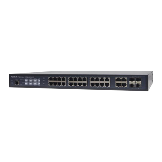
1.2 Front & Rear Panels 1.2.1 Front Panel Figure 1-1. Front Panel of LPGS-2424C Managed Switch The interfaces on the front panel of the Managed Switch are described below: 24 x 10/100/1000Base-T RJ-45 ports (Ports 1-24) 4 x Gigabit combo ports (Ports 25-28): ... -
Page 9: Rear Panel
1.2.2 Rear Panel The Managed Switch provides one fixed AC input power module. Figure 1-2. Rear Panel of LPGS-2424C Managed Switch The interface on the rear panel of the Managed Switch is described below: AC Inlet AC power connection: 100-240V, 50/60Hz Power Switch: ... -
Page 10: Led Definitions
1.3 LED Definitions The Managed Switch is Plug & Play compliant. The real-time operational status can be monitored through a set of LED indicators located in the front panel. Figure 1-3. LEDs of LPGS-2424C Managed Switch Power LED The power status of the Managed Switch is indicated by the Power LED on the front panel of the device. - Page 11 Slowly blinking when you press the Reset button for 13~20 seconds. And then release the Reset button, the LED indicator will continuously blink in orange green color by turns until the system is reset to default (return to supplier default settings) and restart the system.
- Page 12 TP & F/O 25~28 Port LEDs Media Color Operation Type No connection exists. Lit when the 10/100Mbps port link is up. Green Blinking when TP port is receiving and transmitting data at the speed of 10/100Mbps. Lit when the 1000Mbps port link is up. Orange Blinking when TP port is receiving and transmitting data at the speed of 1000Mbps.
-
Page 13: Cable Specifications
1.4 Cable Specifications The following table contains various cable specifications for the Managed Switch. Please make sure that you use the proper cable when connecting the Managed Switch. Cable Type Description UTP Category 3, 4, 5 (100 meters max.) 10Base-T EIA/TIA- 568 150-ohm STP (100 meters max.) UTP Cat. -
Page 14: Chapter 2 Installation
Chapter 2 Installation To properly install the LPGS-2424C Managed Switch, please follow the procedures listed below. These procedures will be respectively described in detail in the following sections. Installation Requirements Checking the Package Contents Installing the Managed Switch ... -
Page 15: Installation Requirements
2.1 Installation Requirements Basic requirements for installation are as follows: Environmental conditions One power outlet Proper ventilation Proper isolation to electrical noise, radio, etc. UTP cables should not run in the same duct with power and phone line cables ... -
Page 16: Installing The Managed Switch
2.3 Installing the Managed Switch You can install the LPGS-2424C switch on a flat surface or mount it in a standard 19-inch network equipment rack. CAUTION To prevent any damage or failure of the Managed Switch, please DO NOT block the ventilation FAN holes. -
Page 17: Rack Installation
2.3.2 Rack Installation In the following section, we will take the LPGS-2424C Managed Switch for example to install a 19- inch switch in a standard 19-inch network equipment rack. WARNING! Please mount the Switch firmly in rack, otherwise it may fall and cause the system damage and possible injury to personnel. -
Page 18: Grounding The Managed Poe Gigabit Ethernet Switch
2.3.3 Grounding the Managed PoE Gigabit Ethernet Switch Grounding helps to limit the effects of noise due to electromagnetic interference (EMI). Be sure to install the ground connection from the ground screw to the grounding surface before connecting devices. Figure 2-2 Grounding Wiring for LPGS-2424C Revision 1.0... -
Page 19: Powering On The Managed Switch
2.4 Powering on the Managed Switch The Managed Switch can be used with AC power supply 100-240V, 50–60Hz. After the Managed Switch is turned on, the Power LED indicators should light in green color and the FAN should spin. For more details about the power LED description, please refer to Section 1.3 LED Definitions. -
Page 20: Removing Sfp Modules
2.6.2 Removing SFP Modules To disconnect an LC connector, use the following guidelines: 1. Press down and hold the locking clips on the upper side of the optic cable. 2. Pull the optic cable out to release it from the transceiver. 3. -
Page 21: Chapter 3 Operation
Chapter 3 Operation A built-in management module of Managed Switch provides users flexible interfaces to configure, control and monitor the system remotely and locally. To know the further information about the operation of Managed Switch, please refer to LPGS-2424C Network Management User’s Manual for the detailed management functions and required installation and operation procedures. - Page 22 SNMP Management SNMP is also In-Band-Management and requires a network connection to the Managed Switch. The Managed Switch private Management Information Bases (MIB) is provided for SNMP-based network management program to configure, control and monitor the system. Web Management Web Management is done over the network. Once the Managed Switch is available on the network, you can login and monitor the status of it through a web browser remotely or locally.
-
Page 23: Chapter 4 Maintenance
Chapter 4 Maintenance This Managed Switch is easy to maintain. The procedures are suggested when you would like to identify faults, perform hardware replacement and firmware upgrade. 4.1 Fault Identification Identifying faults can greatly reduce the times required to find problem and solution. Users may perform local check or remote check to find the problems. -
Page 24: Remote Check
4.1.2 Remote Check Users may check the Managed Switch through SNMP manager remotely. For detailed procedures, please refer to the Network Management User’s Manual. 4.2 Hardware Replacement Procedures WARNING! The Managed Switch contains no user-serviceable parts. DO NOT, UNDER ANY CIRCUMSTANCES, open and attempt to repair it.
Need help?
Do you have a question about the LPGS-2424C Series and is the answer not in the manual?
Questions and answers