
Related Manuals for Lantech IPES-0008A-12V


Summary of Contents for Lantech IPES-0008A-12V
- Page 1 Lantech IPES-0008A-12V 8 10/100TX w/ 8 Booster PoE at/af Injector Industrial Switch User Manual V1.00 Jun 2010...
- Page 2 Recommendation for Shielded network cables STP cables have additional shielding material that is used to reduce external interference. The shield also reduces the emission at any point in the path of the cable. Our recommendation is to deploy an STP network cable in demanding electrical environments. Examples of demanding indoor environments are where the network cable is located in parallel with electrical mains supply cables or where large inductive loads such as motors or contactors are in close vicinity to the camera or its cable.
-
Page 3: Fcc Warning
FCC Warning This Equipment has been tested and found to comply with the limits for a Class-A digital device, pursuant to Part 15 of the FCC rules. These limits are designed to provide reasonable protection against harmful interference in a residential installation. This equipment generates, uses, and can radiate radio frequency energy. -
Page 4: Table Of Contents
Content Introduction .............. 1 Features ..............1 Technical Specification ........... 2 Package Contents ..........4 Safety Precaution ..........4 Hardware Description ..........5 Physical Dimension..........5 Front Panel ............6 Top View ..............6 LED Indicators ............7 Ports ............... 8 Cabling .............. -
Page 5: Introduction
Introduction IPES-0008A-12V Industrial Switch is a cost-effective solution, which meets the high reliability requirements demanded by industrial applications, and also supports to operate in the wide temperature -40°C ~ 75°C environments. Besides, the equipment supports 12V or 48V DC power input and provides the PoE function with 48VDC output for kinds of Powered Devices to receive power as well as data over an RJ-45 cable. -
Page 6: Technical Specification
Technical Specification The technical specifications of IPES-0008A-12V Industrial Switch are listed as follows. Communications Compatibility IEEE 802.3, 802.3u, 802.3x, 802.3af 10/100Base-T Transmission Speed Up to 100 Mbps Interface Connectors 8 x RJ-45 (8-port 10/100TX) 6-pin removable screw terminal (Power & Relay) - Page 7 Mechanism Dimensions (WxHxD) 74mm (W) x 115mm (D) x 152mm (H) Enclosure IP-30, Metal shell with solid mounting kits Mounting DIN-Rail, Wall Mount Protection ESD (Ethernet) 6,000 V Surge (EFT for power) 3,000 V Power Reverse Overload current protection Environment Operating Temperature Standard: -20°C~60°C /-4°F~140°F E models:-40°C~75°C / -40°F~167°F...
-
Page 8: Package Contents
Package Contents Please refer to the package contents list below to verify them against the checklist. IPES-0008A-12V Industrial Switch (with DIN-Rail Bracket) User manual Removable Terminal Block Optional Wall-mount Kit** (2 wall-mount bracket with screws) Compare the contents of the industrial switch with the standard checklist above. If any item is damaged or missing, please contact the local dealer for service. -
Page 9: Hardware Description
In this paragraph, the Industrial switch’s hardware specs, ports, cabling information, and wiring installation will be described. Physical Dimension IPES-0008A-12V Industrial Switch dimensions (W x D x H) is 48.6mm x 95mm x 140mm, the detail dimensions as Figure-1 Figure-1: Mechanical Dimensions... -
Page 10: Front Panel
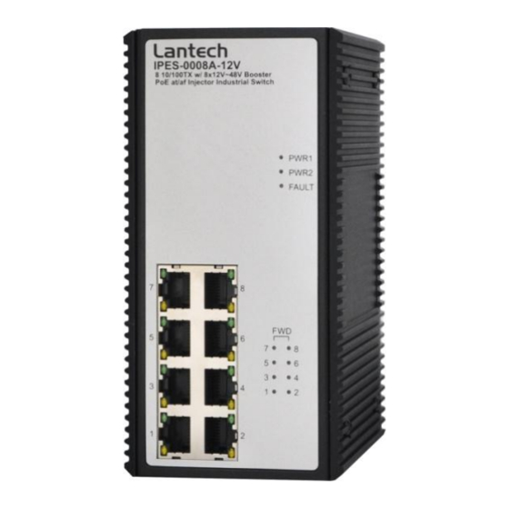
The Front Panel of IPES-0008A-12V Industrial Switch is shown below Figure-2 Figure-2: Front Panel of the PoE Injectors Industrial Switch Top View The top view of IPES-0008A-12V Industrial Switch has one terminal block connector of two DC power inputs and Relay circuit contact. Please refer to Figure-3 for further information. -
Page 11: Led Indicators
LED Indicators The diagnostic LEDs located on the front panel of the industrial switch provide real-time information of system and operation status. Table-1 provides the description of the LEDs status and their definitions for the switch. Color Description Power input 1 is active Green Power input 1 is inactive Power input 2 is active... -
Page 12: Ports
Ports RJ-45 ports The Fast Ethernet ports (RJ-45) will auto-sense for 10Base-T or 100Base-TX connections. Auto MDI/MDI-X means that the switch can connect to another switch or workstation without changing straight-through or crossover cabling. Please refer to Table-2 for RJ-45 pin assignment. Pin Number Assignment Table-2: RJ-45 Pin Assignment... -
Page 13: Cabling
The following figures show the cable schematic for straight-through type (Figure-4) and crossover type (Figure-5). Switch Router / PC 3 TD+ 3 RD+ 6 TD- 6 RD- 1 RD+ 1 TD+ 2 RD- 2 TD- Figure-4: Straight Through Cable Schematic Switch Switch 3 TD+... -
Page 14: Wiring The Power Inputs
Wiring the Power Inputs Please follow the steps below to wire the power cord which from the other compliant external DC power supplier. Insert the positive and negative wires into the PWR1 (V+, V-) and PWR2 (V+, V-) contacts on the terminal block connector as shown in Figure-6. Figure-6: Terminal Block Front View for Power1 &... - Page 15 Power Restriction (under - 48VDC power) IPES-0008A-12V only can support one -48VDC power source. If using two -48VDC power source, IPES-0008A-12V may cause damage.
-
Page 16: Wiring The Fault Alarm Contact
Wiring the Fault Alarm Contact The fault alarm contact is in the middle of terminal block connector as the picture shows below. Inserting the wires, will detect the fault status including power failure or port link failure (managed industrial switch only) and from a Normally Close circuit. Please refer to Figure-8 for the fault alarm contact, and Figure-9 shows the application example for the fault alarm operation. -
Page 17: Mounting Installation
Mounting Installation DIN-Rail Mounting The DIN-Rail bracket is screwed on the switch on the production line in the factory. If the bracket is not screwed on the switch, please refer to Figure-10 to screw it on the switch. Follow the steps below to hang the industrial switch. DIN-Rail Bracket Figure-10: Rear side of the PoE Injectors Industrial Switch... - Page 18 After the DIN-Rail bracket is screwed on the rear side of the switch, insert the top of the bracket into the rail as Figure-11. Figure-11 Then, lightly pull-down the bracket into the rail as shown in Figure-12. Figure-12 Check if the bracket is tightened on the rail or not. To remove the switch from the rail, reverse steps above.
-
Page 19: Wall Mounting
Wall Mounting**(optional) Please refer to Figure-13 and follow the steps below to mount the industrial switch with wall-mount bracket, and the detail dimension of the bracket as Figure-14. 1. Remove the DIN-Rail bracket from the switch; loose the screws to remove it. 2. -
Page 20: Hardware Installation
Hardware Installation In this paragraph, we are going to explain how to install IPES-0008A-12V Industrial Switch and the installation points to be attended to it. Installation Steps 1. Unpack the Industrial switch packing. 2. Check if the DIN-Rail bracket is screwed on the Industrial switch or not. If the bracket is not screwed on the Industrial switch, please refer to DIN-Rail Mounting section for DIN-Rail installation. -
Page 21: Network Application
Network Application This segment provides the sample to help user have more actual idea of industrial switch application. For a sample application of the industrial switch, see the Figure-15 below. IPES-0008A-12V Industrial Switch Figure-15: Network Application... -
Page 22: Troubleshooting
Troubleshooting Verify that you are using the right power cord/supplier/adapter (DC 12V/48V), please don’t use the power supplier/adapter with a non-compliant DC output voltage, or it will burn the equipment. Select the proper UTP/STP cable to construct your network. Please check that you are using the right cable.
Need help?
Do you have a question about the IPES-0008A-12V and is the answer not in the manual?
Questions and answers