
Subscribe to Our Youtube Channel
Related Manuals for Lantech LGS-2816C-RPS


Summary of Contents for Lantech LGS-2816C-RPS
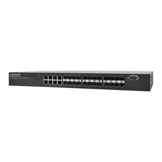
- Page 1 Lantech LGS-2816C-RPS 16 100/1000M SFP+ 8 10/100/1000T/Dual Speed SFP Combo L2 Plus Managed Switch w/ Redundant Power Supply User Manual...
- Page 2 A N A G E M E N T U I D E LGS-2816C-RPS 16 100/1000M SFP+ 8 10/100/1000T/Dual Speed SFP Combo L2 Plus Managed Switch w/ Redundant Power Supply LGS-2816C-RPS Publication date: March., 2011 Revision v5.17...
- Page 3 BOUT UIDE This guide gives specific information on how to operate and URPOSE use the management functions of the switch. The guide is intended for use by network administrators who UDIENCE are responsible for operating and maintaining network equipment; consequently, it assumes a basic working knowledge of general switch functions, the Internet Protocol (IP), and Simple Network Management Protocol (SNMP).
-
Page 4: Revision History
Revision History Release Date Revision 5.17 01/10/2010... - Page 5 ONTENTS...
- Page 6 ECTION ETTING TARTED This section provides an overview of the switch, and introduces some basic concepts about network switches. It also describes the basic settings required to access the management interface. This section includes these chapters: ―Introduction‖ ◆ ―Initial Switch Configuration‖ ◆...
- Page 7 NTRODUCTION This switch provides a broad range of features for Layer 2 plus switching. It includes a management agent that allows you to configure the features listed in this manual. The default configuration can be used for most of the features provided by this switch. However, there are many options that you should configure to maximize the switch‘s performance for your particular network environment.
- Page 8 Table 1-2: Key Features (Continued) Feature Description Virtual LANs Up to 4K using IEEE 802.1Q, port-based, and private VLANs Traffic Prioritization Queue mode and CoS configured by Ethernet type, VLAN ID, TCP/ UDP port, DSCP, ToS bit, VLAN tag priority, or port Qualify of Service Supports Differentiated Services (DiffServ), and DSCP remarking...
- Page 9 This switch provides management access via the console port, ECURIY AND Telnet, or a web browser. User names and passwords can be UTHENTICATION configured locally or can be verified via a remote authentication server (i.e., RADIUS or TACACS+). Port-based authentication is also supported via the IEEE 802.1X protocol.
- Page 10 Provide a D-Sub connector on rear panel to connect to RP-2000 EDUDANT External/Redundant system provide full power cord OWER UPPLY redundancy solution that can protect against a single power main failure You can manually configure the speed and duplex mode, and flow ONFIGURATION control used on specific ports, or use auto-negotiation to detect the connection settings used by the attached device.
- Page 11 The switch supports these spanning tree protocols: PANNING LGORITHM Spanning Tree Protocol (STP, IEEE 802.1D) – Supported by using the STP backward compatible mode provided by RSTP. STP provides loop detection. When there are multiple physical paths between segments, this protocol will choose a single path and disable all others to ensure that only one route exists between any two stations on the network.
- Page 12 Differentiated Services (DiffServ) provides policy-based management UALITY OF ERVICE mechanisms used for prioritizing network resources to meet the requirements of specific traffic types. Each packet is classified upon entry into the network based on access lists, DSCP values, or VLAN lists. Using access lists allows you select traffic based on Layer 2, Layer 3, or Layer 4 information contained in each packet.
- Page 13 Default Console Port Connection Baud Rate 115200 bps Data bits Stop bits Parity none Local Console Timeout 0 (disabled) System Information Device Name LGS-2816C-RPS Account Admin User admin/admin Guest User guest/guest Time Manual/NTP Manual NTP Server 209.81.9.7 Time Zone GMT+8:00...
- Page 14 Table: System Defaults (Continued) Function Parameter Default Tag-based Group VLAN ID VLAN Name Default IGMP Aware Disable Private VLAN Disable GVRP propagation Disable Member Port 1-24 ports Port-based Group VLAN Name Default Member Port 1-24 ports VLAN Ports Tag Identifier 0x8100 VLAN Aware Enable...
- Page 15 Table : System Defaults (Continued) Function Parameter Default Queuing Mode Strict Priority Queue Weighted Low Queue Weighted Normal Queue Weighted Medium Queue Weighted High QoS Control List QoS Control List None Rate Limiters Ingress Enable Disabled Ingress Rate Ingress Unit Kbps Egress Enable Disabled...
- Page 16 Management Protocol). This SNMP agent permits the switch to be managed from any system in the network using network management software such as Lantech View. The switch‘s web interface, console interface, and SNMP agent allow you to perform the following management functions: Set the administrator password ...
- Page 17 Set the speed/duplex mode for any port Configure the bandwidth of any port by limiting input or output rates or enable the Flow control of any port Control port access through IEEE 802.1X security or static address filtering Filter packets using Access Control Lists (ACLs) ...
- Page 18 Set the data format to 8 data bits, 1 stop bit, and no parity. ■ Set flow control to none. ■ Set the emulation mode to VT100. ■ When using HyperTerminal, select Terminal keys, not ■ Windows keys. Once you have set up the terminal correctly, the console login screen will be displayed.
- Page 19 Then enter account configuration interface. Type ―modify admin,‖ where password is your new password. Managed Switch - LGS-2816C-RPS Login: admin Password: ***** LGS-2816C-RPS(account)# modify admin username/password: the length is from 5 to 15. Current username (admin):admin Current password: New password: Confirm password: Username changed successfully.
- Page 20 Login: admin Password: ***** LGS-2816C-RPS# ip LGS-2816C-RPS(ip)# set ip ? Usage: set <ip> [mask] [gateway] LGS-2816C-RPS(ip)# LGS-2816C-RPS(ip)# set ip 192.168.20.15 255.255.255.0 192.168.20.250> YNAMIC ONFIGURATION BTAINING AN DDRESS If you enable the ―dhcp‖ option, IP will be enabled but will not function until a DHCP reply has been received.
- Page 21 SNMP NABLING Simple Network Management Protocol (SNMP) applications such as ANAGEMENT Lantech View. You can configure the switch to (1) respond to SNMP CCESS requests or (2) generate SNMP traps. When SNMP management stations send requests to the switch (either to return information or to set a parameter), the switch provides the requested data or sets the specified parameter.
- Page 22 To change the read-only or read/write community string, type either of the following commands, and press <Enter>. “ set community <Community> <user_name> <Source IP> <Source Mask> “ LGS-2816C-RPS(snmp)# set community public publicuser 0.0.0.0 0.0.0.0 LGS-2816C-RPS(snmp)# MIL-SM24DPA(snmp)# show community SNMP Community Table:...
- Page 23 For a more detailed description of these parameters and other SNMP commands. The following example creates a trap host for a version 1 SNMP client. >snmp trap version 1 LGS-2816C-RPS(snmp)# set trap 1 2 192.168.1.10 162 public LGS-2816C-RPS(snmp)# LGS-2816C-RPS(snmp)# show trap SNMPv3 Trap Host Configuration: Ver.
- Page 24 <Enter>.“config load tftp-server file-name‖ Managed Switch- LGS-2816C-PRS Login: admin Passward:***** LGS-2816C-PRS# config-file LGS-2816C-PRS(config-file)# LGS-2816C-PRS(config-file)# import ? Usage: import <current│user> <ip_address> <file_path> Ip_address : TFTP server ip address. File_path : Configuration file path. LGS-2816C-PRS(config-file)# import user 192.168.20.1 LGS-2816C-RPS.config – 42 –...
- Page 25 ECTION ECTION ONFIGURATION This section describes the basic switch features, along with a detailed description of how to configure each feature via a web browser. This section includes these chapters: ―Using the Web Interface‖ ◆ ―Configuring the Switch‖ ◆...
- Page 26 SING THE NTERFACE This switch has an embedded HTTP web agent. Using a web browser you can configure the switch and view statistics to monitor network activity. The web agent can be accessed by any computer on the network using a standard web browser (Microsoft IE 6.0 above, Netscape V7.1 above or FireFox V1.00).
- Page 27 AVIGATING ROWSER NTERFACE To access the web-browser interface you must first enter a user name and password. By default, the user name is ―admin‖ and there is no password. When your web browser connects with the switch‘s web agent, the home page is displayed as shown below.
- Page 28 The web agent displays an image of the switch‘s ports. The refresh mode ANEL ISPLAY is auto-mode by default. Clicking on the image of a port opens the Detailed Statistics page as described on page 143. Figure 2: Front Panel Indicators Using the onboard web agent, you can define system parameters, manage and control the switch, and all its ports, or monitor network conditions.
- Page 29 | Using the Web Interface HAPTER Navigating the Web Browser Interface Port Isolation Configures Port Isolation setting Management Configures Management VLAN ID VLAN MAC Address Configures MAC Address Aging parameters setting Table Static Filter Configures MAC Address Static Filter settting Static Forward Configures MAC Address Static Forward setting MAC Alias...
- Page 30 | Using the Web Interface HAPTER Navigating the Web Browser Interface Wizard Configures ACL via Wizard setting IP MAC Binding Configures IP MAC Port Binding settings Configuration Configures role using dynamic entry of IP Address, MAC, Dynamic Entry Port and VID 802.1X Server Configures RADIUS Authentication and Accounting Server...
- Page 31 | Using the Web Interface HAPTER Navigating the Web Browser Interface Proxy Configures IGMP Proxy parameters setting Snooping Configures IGMP Snooping parameters setting IGMP Group Configures IGMP Group Allow parameters setting Allow Group Display IGMP Group Membership detail information Membership Configures MVR parameters setting MVID Configures Multicast MVID and display the detail...
- Page 32 | Using the Web Interface HAPTER Navigating the Web Browser Interface Export/ Import Allows user can back up or reload the configuration files of Save AS Start or Save As User via TFTP Server Diagnotics Diagnostics Provides a set of basic system diagnosis. The basic system check includes EEPROM test, UART test, DRAM test and Flash test Ping...
-
Page 33: C Onfiguring The S Witch
ONFIGURING THE WITCH This chapter describes all of the basic configuration tasks. ONFIGURING YSTEM NFORMATION You can identify the system by configuring the contact information, name, and location of the switch. NTERFACE To configure System Information in the web interface: Click SYSTEM, System, Information. - Page 34 You can configure this parameter through the device‘s user interface or SNMP. Device name –The name of the switch. User-defined. Default is LGS-2816C-RPS. – 52 –...
- Page 35 Serial number – The serial number is assigned by Lantech. Host IP address – The IP address of the switch. Host MAC address – It is the Ethernet MAC address of ...
- Page 36 | Configuring the Switch | Configuring the Switch HAPTER HAPTER Setting Account Setting Account – To display the Redundant Power Supply system fan status with rotation speed. – Voltage To display the Redundant Power Supply system voltage value –...
- Page 37 | Configuring the Switch | Configuring the Switch HAPTER HAPTER Setting Account Setting Account ONFIGURING CCOUNT In this function, only administrator can create, modify or delete the username and password. Administrator can modify other guest identities‘ password without confirming the password but it is necessary to modify the administrator- equivalent identity.
- Page 38 ONFIGURING The switch provides manual and automatic ways to set the system time via NTP. Manual setting is simple and you just input ―Year‖, ―Month‖, ―Day‖, ―Hour‖, ―Minute‖ and ―Second‖ within the valid value range indicated in each item. NTP is a well-known protocol used to synchronize the clock of the switch system time over a network.
-
Page 39: Table Of Contents
| Configuring the Switch HAPTER Setting Virtual Stack ARAMETERS These parameters are displayed on the Time configuration page: Current Time – To display the current time of the system Manual – To fill the valid figures in the fields of Year, ... - Page 40 | Configuring the Switch HAPTER Setting Virtual Stack Default: 1 Hour: Range is 0 ~ 23. Default: 0 Apply – To save the configuration to switch flash memory. – 58 –...
- Page 41 IP A ETTING DDRESS This section describes how to configure an IP interface for management access to the switch over the network. This switch supports IP Version 4, and can be managed simultaneously through either of the address types. You can manually configure a specific IPv4 address or direct the switch to obtain an IPv4 address from a DHCP server when it is powered on.
- Page 42 ARAMETERS These parameters are displayed on the Time configuration page: DHCP Setting – To set enable or disable the switch obtained a IP address from DHCP Server. Default is disable IP address – Address of the switch, Valid IP addresses ...
- Page 43 ONFIGURING ETECTION The loop detection is used to detect the presence of traffic. When switch receives packet‘s(looping detection frame) MAC address the same as oneself from port, show Loop detection happens. The port will be locked when it received the looping detection frames.
- Page 44 ONFIGURING ANAGEMENT OLICY Through the management security configuration, the manager can do the strict setup to control the switch and limit the user to access this switch. NTERFACE To configure Management Policy in the web interface: Click SYSTEM, Management Policy. Add a Management policy rule.
-
Page 45: Range Is
Figure 4-6: Management Policy Configuration ARAMETERS These parameters are displayed on the Management Policy configuration page: Add. – To create a new management policy. Specify new entry of Management Security Configuration can be created after the parameters as mentioned above had been setup Delete –... -
Page 46: Default
IP Range - The switch supports two kinds of options for managed valid IP Range, including ―Any‖ and ―Custom‖. Default is ―Any‖. In case that‖ Custom‖ had been chosen, you can assigned effective IP range. The valid range is 0.0.0.0~255.255.255.255. Incoming Port - The switch supports two kinds of options for ... - Page 47 ONFIGURING YSLOG The Syslog is a standard for logging program messages . It allows separation of the software that generates messages from the system that stores them and the software that reports and analyzes them. It can be used as well a generalized informational, analysis and debugging messages.
- Page 48 ONFIGURING YSTEM The System Log provides information about system logs, including information when the device was booted, how the ports are operating, when users logged in, when sessions timed out, as well as other system information. NTERFACE To configure System Log in the web interface: Click SYSTEM, System Log.
- Page 49 ONFIGURING IRTUAL TACK Virtual Stack Management(VSM) is the group management function. Through the proper configuration of this function, switches in the same LAN will be grouped automatically. And among these switch, one switch will be a master machine, and the others in this group will become the slave devices. information. VSM offers a simple centralized management function.
- Page 50 ARAMETERS These parameters are displayed on the Virtual Stack page: State – It is used for the activation or de-activation of VSM. Default is Enable. Role - The role that the switch would like to play in virtual stack. ...
- Page 51 ONFIGURING ONFIGURATION The Port Configuration page includes configuration options for enabling auto-negotiation or manually setting the speed and duplex mode, enabling flow control, setting the maximum frame size, specifying the response to excessive collisions, or enabling power saving mode. Port Configuration is applied to change the setting of each port.
- Page 52 | Configuring the Switch HAPTER Configuring Power Saving Auto - Enables auto-negotiation. When using auto-negotiation, the ■ optimal settings will be negotiated between the link partners based on their advertised capabilities. 1G FDX - Supports 1 Gbps full-duplex operation ■ 100Mbps FDX - Supports 100 Mbps full-duplex operation ■...
- Page 53 ONFIGURING TATUS The function Port Status gathers the information of all ports‘ current status and reports it by the order of port number, media, link status, port state, Auto-Negotiation status, speed/duplex, Rx Pause and Tx Pause. An extra media type information for the module ports1 to 8 is also offered.
- Page 54 | Configuring the Switch HAPTER Configuring Power Saving Description - network managers provide a description of device ports. – 72 –...
- Page 55 NTERFACE To display the Port Port 1 ~ Port 24 SFP information in the web interface: Right Click Port connected icon. Display the Port detail information. Figure 4-12: Port 1~ Port 24 SFP Detail Information ARAMETERS These parameters are displayed on the Port Detial information page: Connector Type –...
- Page 56 | Configuring the Switch HAPTER Configuring Power Saving the manufacturer. – 74 –...
- Page 57 Data Code - Show the date this SFP module was made. Temperature - Show the current temperature of SFP module. Vcc - Show the working DC voltage of SFP module. Mon1 (Bias) mA - Show the Bias current of SFP module. ...
- Page 58 ONFIGURING IMPLE OUNTER The function of Simple Counter collects any information and provides the counting about the traffic of the port, no matter the packet is good or bad. The window can show all ports‘ counter information at the same time. Each data field has 20-digit long.
- Page 59 Receive - Number of bad packets received. ◆ Drops – Transmit–Number of packets transmitted drop. ◆ Receive - Number of packets received drop. ◆ Auto-refresh - The simple counts will be refreshed automatically ◆ on the UI screen. Refresh - The simple counts will be refreshed manually when ◆...
-
Page 60: Range Is
ONFIGURING ETAIL OUNTER The function of Detail Counter collects any information and provides the counting about the traffic of the port, no matter the packet is good or bad. Each data field has 20-digit long. If the counting is overflow, the counter will be reset and restart counting. - Page 61 Rx Broadcast - Show the counting number of the received broadcast packet. Rx Multicast - Show the counting number of the received multicast packet. TX Packets - The counting number of the packet transmitted. TX Octets - Total transmitted bytes. ...
- Page 62 | Configuring the Switch HAPTER Configuring Power Saving CRC. Rx Jabber - Number of long frames(according tomax_length register) with invalid CRC. Rx Drops - Frames dropped due to the lack of receiving buffer. Rx Errors - Number of the error packet received. ...
- Page 63 ONFIGURING OWER AVING The function of Power Saving and provides the Power saving for reduce power consumption with "ActiPHY Power Management" "PerfectReach Power Management" two technique.It could efficient saving the switch Power when the client idle and detec the cable length to provide different power.
- Page 64 802.1Q V LANS The switch supports Tag-based VLAN (802.1Q) and Port-based VLAN. Support 4094 active VLANs and VLAN ID 1~4094. VLAN configuration is used to partition your LAN into small ones as your demand. Properly configuring it, you can gain not only improving security and increasing performance but greatly reducing VLAN management.
- Page 65 | Configuring the Switch HAPTER Configure SNMP ARAMETERS These parameters are displayed on the VLAN Mode Configuration page: Port-based - Port-based VLAN is defined by port. Any packet coming in or outgoing from any one port of a port-based VLAN will be accepted.
- Page 66 Segment Forwarding Port Mapping Port 01 Port 02 Port 03 Port 04 Port 05 Port 06 Port 07 Port 08 Port 09 Port 10 Port 11 Port 12 Port 13 Port 14 Port 15 Port 16 Port 17 ...
- Page 67 ONFIGURING ASED ROUP The function shows the information of existed Tag-based VLAN Groups, You can also easily create, edit and delete a Tag-based VLAN group by pressing <Add>, <Edit> and <Delete> function buttons. User can add a new VLAN group by inputting a new VLAN name and VLAN ID. NTERFACE To Configure the Tag-based Group in the web interface: Click VLAN, Tag-based Group.
- Page 68 VLAN ID - VLAN identifier. Each tag-based VLAN group has a unique VID. It appears only in tag-based and Double-tag mode. IGMP Proxy - IGMP proxy enables the switch to issue IGMP host messages on behalf of hosts that the system discovered through standard IGMP interfaces.
- Page 70 | Configuring the Switch HAPTER Configure SNMP ONFIGURING ASED ROUP The function shows the information of the existed Port-based VLAN Groups. You can easily create, edit and delete a Port-based VLAN group by pressing <Add>, <Edit> and <Delete> function buttons. User can add a new VLAN group by inputting a new VLAN name.
- Page 71 | Configuring the Switch HAPTER Configure SNMP ONFIGURING ORTS The function in VLAN Tag Rule Setting, user can input VID number to each port. The range of VID number is from 1 to 4094. User also can choose ingress filtering rules to each port. There are two ingress filtering rules which can be applied to the switch.
-
Page 72: Range Is
| Configuring the Switch HAPTER Configure SNMP PVID - This PVID range will be 1-4094. Before you set a number x as PVID, you have to create a Tag-based VLAN with VID x. For example, if port x receives an untagged packet, the switch will apply the PVID (assume as VID y) of port x to tag this packet, the packet then will be forwarded as the tagged packet with VID y. - Page 73 ONFIGURING SOLATION Port Isolation provides for an apparatus and method to isolate ports on layer 2 switches on the same VLAN to restrict traffic flow. The apparatus comprises a switch having said plurality of ports, each port configured as a protected port or a non-protected port. An address table memory stores an address table having a destination address and port number pair.
- Page 74 | Configuring the Switch HAPTER Configure SNMP ONFIGURING ANAGEMENT To assign a specific VLAN for management purpose. The management VLAN is used to establish an IP connection to the switch from a workstation connected to a port in the VLAN. This connection supports a VSM, SNMP, and Telnet session.
- Page 75 ONFIGURING MAC Table Configuration gathers many functions, including MAC Table Information, MAC Table Maintenance, Static Forward, Static Filter and MAC Alias, which cannot be categorized to some function type. They are described below. NTERFACE To Configure the MAC Address Table in the web interface: Click MAC, MAC Address Table.
- Page 76 | Configuring the Switch HAPTER Configure SNMP Auto - Enable this port MAC address dynamic learning mechanism. Disable - Disable this port MAC address dynamic learning mechanism, only support static MAC address setting. Secure - Disable this port MAC address dynamic learning ...
-
Page 77: Range Is
ONFIGURING TATIC ILTER Static Filter is a function that denies the packet forwarding if the packet‘s MAC Address is listed in the filtering Static Filter table. User can very easily maintain the table by filling in MAC Address, VID (VLAN ID) and Alias fields individually. - Page 78 ONFIGURING TATIC ORWARD Static Forward is a function that allows the user in the static forward table to access a specified port of the switch. Static Forward table associated with a specified port of a switch is set up by manually inputting MAC address and its alias name.
- Page 79 ONFIGURING LIAS MAC Alias function is used to let you assign MAC address a plain English name. At the initial time, it shows all pairs of the existed alias name and MAC address. There are three MAC alias functions in this function folder, including MAC Alias Add, MAC Alias Edit and MAC Alias Delete.
- Page 80 ONFIGURING ABLE MAC Table function is used to display the static or dynamic learning MAC entry and the state for the selected port. There are five MAC Table information display on the Web GUI, including MAC Alias, MAC Address, Port, VID and State. NTERFACE To display the MAC Table in the web interface: Click MAC, MAC Table.
-
Page 81: Default
ONFIGURING GVRP is an application based on Generic Attribute Registration Protocol (GARP), mainly used to automatically and dynamically maintain the group membership information of the VLANs. The GVRP offers the function providing the VLAN registration service through a GARP application. It makes use of GARP Information Declaration (GID) to maintain the ports associated with their attribute database and GARP Information Propagation (GIP) to communicate among switches and end stations. - Page 82 | Configuring the Switch HAPTER Configure SNMP Leave All Time - A time period for announcement that all registered device is going to be de-registered. If someone still issues a new join, then a registration will be kept in the switch. Valid range: 1000-5000 unit time, Default: 1000 unit time.
- Page 83 ONFIGURING OUNTER All GVRP counters are mainly divided into Received and Transmitted two categories to let you monitor the GVRP actions. Actually, they are GARP packets. NTERFACE To display the GVRP Counter in the web interface: Click GVRP, Counter. Scroll which port you want to display the GVRP Counter information. Click Refresh to modify the GVRP Counter information.
- Page 84 GVRP application. JoinIn Message Packets: Number of GVRP BPDU with Join In message is received by the GVRP application. LeaveEmpty Message Packets: Number of GVRP BPDU with Leave Empty message is received by the GVRP application. Transmitted – Total GVRP Packets: Total GVRP BPDU is received by the GVRP application.
- Page 85 ONFIGURING ROUP The Function will display the dynamic group member and their detail imformation. Others it also provide a configuration item to edit administrative Control parameters. The detail information includes VID and Member Port. NTERFACE To display the Group in the web interface: Click GVRP, Group.
- Page 86 ONFIGURING UALITY ERVICE The switch support four QoS queues per port with strict or weighted fair queuing scheduling. There are 24 QoS Control Lists (QCL) for advance programmable QoS classification, based on IEEE 802.1p, Ethertype, VID, IPv4/IPv6 DSCP and UDP/TCP ports and ranges. High flexibility in the classification of incoming frames to a QoS class.
- Page 87 Default Class - User can set up High Priority or Low Priority for each port respectively. You could scroll with Low / Normal / Medium / High QCL - The number of QCL rule 1~24, each port have to apply one ...
- Page 88 ONFIGURING ONTROL The switch support four QoS queues per port with strict or weighted fair queuing scheduling. There are 24 QoS Control Lists (QCL) for advance programmable QoS classification, based on IEEE 802.1p, Ether Type, VID, IPv4/IPv6 DSCP and UDP/TCP ports and ranges. NTERFACE To display the QoS Control List Configuration in the web interface: Click QoS, QoS Control List.
- Page 89 Ethertype Protocol (Hexadecimal) 0x0800 IP, Internet Protocol 0x0801 X.75 Internet 0x0802 NBS Internet 0x0803 ECMA Internet 0x0804 Chaosnet 0x0805 X.25 Level 3 0x0806 ARP, Address Resolution Protocol. 0x0808 Frame Relay ARP [RFC1701] 0x6559 Raw Frame Relay [RFC1701] DRARP, Dynamic RARP. RARP, Reverse 0x8035 Address Resolution Protocol.
- Page 90 0x8E88 EAPOL, EAP over LAN. 0x9000 Loopback (Configuration Test Protocol) 0xFFFF reserved. VLAN ID - The configurable VID range:1~4094. UDP/TCP Port - To select the UDP/TCP port classification method by Range or Specific. UDP/TCP Port Range - The configurable ports range: ...
- Page 91 ONFIGURING IMITERS Each port includes an ingress policer, and an egress shaper, which can limit the bandwidth of received and transmitted frames. Ingress policer or egress shaper operation is controlled per port in the Rate Limit Configuration. NTERFACE To display the QoS Rate Limiters Configuration in the web interface: Click QoS, Rate limiters.
- Page 92 Egress Shaper Enabled – Evoke to enable the Egress rate limiter rule. Egress Rate (rule) - - Configures the rate for the port shaper. (Range: 500-1000000 kbps, or 1-1000 Mbps; Default: 500 kbps) Egress Shaper Unit – Sets the unit of measure for the port shaper. ...
- Page 93 ONFIGURING TORM ONTROL You can configure limits on broadcast, multicast and unknown unicast traffic to control traffic storms which may occur when a network device is malfunctioning, the network is not properly configured, or application programs are not well designed or properly configured. Traffic storms caused by any of these problems can severely degrade performance or bring your network to a complete halt.
- Page 94 Rate (pps) - The threshold above which packets are dropped. This limit can be set by specifying a value of 2n packets per second (pps), or by selecting one of the options in Kpps. 1 / 2 / 4 / 8 / 16 / 32 / 64 / 128 / 256 / 512 / 1K / 2K / 4K / 8K / 16K / 32K / 64K / 128K / 256K / 512K / 1024K Due to an ASIC limitation, the enforced rate limits are slightly less...
- Page 95 ONFIGURING IZARD You can use the QCL configuration Wizard is targeted on user can easy to configure the QCL rules for QoS configuration. The wizard provide the typical network application rules, user can apply these application easily. NTERFACE To configure QoS Wizard: Click QoS, Wizard.
- Page 96 4-35 Figure : Set up Policy Rules ARAMETERS These parameters are displayed on the QCL Wizard page: QCL ID – Display the QoS Control List (QCL) Index from 1 to 24 Port Member – Evoke the port to join the QCL ID and become the ...
- Page 97 Figure 4-36: Set up Port Policy Finish Figure 4-37: Set up Typical Network Application Rules ARAMETERS These parameters are displayed on the QCL Wizard page: Audio and Video – QuickTime 4 Server / MSN Messenger Phone / Yahoo Messenger Phone / Napster / Real Audio Games - Blizzard Battlenet (Diablo2 and StarCraft) / Fighter Ace II / ...
- Page 98 Figure 4-38: Set up Typical Network Application Rules ARAMETERS These parameters are displayed on the QCL Wizard page: QCL ID – Scroll to set the QCL ID from 1 to 24 Traffic Class – Scroll to set the Traffic Class with Low/ Normal/ ...
- Page 99 ARAMETERS These parameters are displayed on the QCL Wizard page: QCL ID – Scroll to set the QCL ID from 1 to 24 TOS Precedence 0- 7 Class – Scroll to set the TOS Precedence Mapping Class with Low/ Normal/ Medium/ High Figure 4-40: Set up VLAN Tag Priority Mapping Rules ARAMETERS These parameters are displayed on the QCL Wizard page:...
- Page 100 ONFIGURING IMPLE ETWORK ANAGEMENT ROTOCOL Simple Network Management Protocol (SNMP) is a communication protocol designed specifically for managing devices on a network. Equipment commonly managed with SNMP. SNMP is typically used to configure these devices for proper operation in a network environment, as well as to monitor them to evaluate performance or detect potential problems.
- Page 101 This function is used to configure SNMP settings, community name, SNMP SYSTEM trap host and public traps as well as the throttle of SNMP. A SNMP CONFIGRATION manager must pass authentication identifying both community names, then it can access the MIB information of the target device.
- Page 102 The function is used to configure SNMPv3 communities. The SNMPv3 Community and UserName is unique. To create a new community COMMUNITIES account, please check <Add new community> button, and enter CONFIGRATION account information then check <Save>. Group Number : 4. NTERFACE To configure SNMPv3 Communities setting: Click SNMP, Communities.
- Page 103 The function is used to configure SNMPv3 user. The Entry index key SNMPv3 USERS is UserName. To create a new UserName account, please check CONFIGRATION <Add new user> button, and enter the user information then check <Save>. Max Group Number : 10. NTERFACE To configure SNMPv3 Users setting: Click SNMP, Users.
- Page 104 Authentication Protocol – Scroll to choice two methods as MD5 and SHA for Authentication protocol. Authentication Password –Specify the Authentication Password field. The length of 'MD5 Authentication PWD' is restricted to 8 – 32. The length of 'SHA Authentication PWD' is restricted to 8 – 40. Privacy Protocol –...
- Page 105 The function is used to configure SNMPv3 group. The Entry index SNMPv3 G ROUPS key are Security Model and Security Name. To create a new group ONFIGRATION account, please check <Add new group> button, and enter the group information then check <Save>. Max Group Number : v1: 2, v2: 2, v3:10.
- Page 106 Security Model – Scroll to choice the security model as v1: SNMPv1, v2c: SNMPv2c or usm: User-based Security Model.The length of ―UserName‖ string is restricted to 1-32. Security Name – Scroll to choice the UserName you set on the ...
- Page 107 The function is used to configure SNMPv3 view. The Entry index key SNMPv3 V IEWS are OID Subtree and View Name. To create a new view account, ONFIGRATION please check <Add new view> button, and enter the view information then check <Save>. Max Group Number : 28. NTERFACE To configure SNMPv3 Views setting: Click SNMP, Views.
- Page 108 The function is used to configure SNMPv3 accesses. The Entry index SNMPv3 A CCESSES key are Group Name, Security Model and Security level. To create a ONFIGRATION new access account, please check <Add new access> button, and enter the access information then check <Save>. Max Group Number : 14.
- Page 109 Auth, Priv: Authentication and privacy. Read View Name – Scroll to choice the read view name. The name of MIB view. Select ―None‖, this entry has no read right. Write View Name - Scroll to choice the write view name. The ...
- Page 110 The function is used to configure SNMP trap. To create a new trap OSTS account, please check <No number> button, and enter the trap ONFIGRATION information then check <Apply>. Max Group Number : 6. NTERFACE To configure SNMP Trap Hosts setting: Click SNMP, Trap Hosts.
- Page 111 Version – Scroll SNMP Version to choice the trap method as v1, v2c or v3. IP – Specify the IP field. The field is the SNMP Host IP Address. Port – Specify the Port field. Port number. Default: 162. ...
- Page 112 ONFIGURING CCESS ONTROL ISTs An Access Control List (ACL) is a sequential list of permit or deny conditions that apply to IP addresses, MAC addresses, or other more specific criteria. This switch tests ingress packets against the conditions in an ACL one by one. A packet will be accepted as soon as it matches a permit rule, or dropped as soon as it matches a deny rule.
- Page 113 Repeat the preceding step for each port to which an ACL will be applied. Click Apply. Figure 4-48: ACL Ports Configuration ARAMETERS These parameters are displayed on the SNMP Trap Hosts Setting page: Port # – Port Identifier. Port number: 1~24. ...
- Page 114 Rate Limiter ID - Specifies a rate limiter to apply to the port. (Rate Limiter ID Range: 1~16. To select one of rate limiter ID for this port, it will limit met ACL packets by rate limiter ID configuration. Default: Disabled).
- Page 115 The ACL Rate Limiter Configuration page is used to define the rate ACL R ATE LIMITERs limits applied to a port (as configured either through the ACL Ports ONFIGRATION Configuration menu or the Access Control List Configuration menu.. NTERFACE To configure rate limits which can be applied to a port: Click Configuration, ACL, Rate Limiters.
- Page 116 The Access Control List Configuration page is used to define CCESS ONTROL filtering rules for an ACL policy, for a specific port, or for all ports. ONFIGRATION Rules applied to a port take effect immediately, while those defined for a policy must be mapped to one or more ports using the ACL Ports Configuration menu..
- Page 117 Figure 4- 50: Access Control List Configuration...
- Page 118 The following buttons are used to edit or move the ACL entry (ACE): Table: ACE Modification Buttons Button Description Inserts a new ACE before the current row. Edits the ACE. Moves the ACE up the list. Moves the ACE down the list.
- Page 119 EtherType Filter - This option can only be used to filter Ethernet II formatted packets. (Options: Any, Specific (600-ffff hex); Default: Any) A detailed listing of Ethernet protocol types can be found in RFC1060. A few of the more common types include 0800 (IP), 0806 (ARP), 8137 (IPX).
- Page 120 | Configuring the Switch HAPTER to the DMAC address; Default: Any) Configure SNMP IP/Ethernet Length - Specifies whether frames can be matched according to their ARP/RARP hardware address length (HLN) and protocol address length (PLN) settings. (Options: Any - any value is allowed, 0 - ARP/RARP frames where the HLN is equal to Ethernet (0x06) and the (PLN) is equal to IPv4 (0x04) must not match this entry, 1 - ARP/RARP frames where the HLN is equal to Ethernet...
- Page 121 TCP Parameters Source Port Filter - Specifies the TCP source filter for this rule. (Options: Any, Specific (0-65535), Range (0-65535);Default: Any) Dest. Port Filter - Specifies the TCP destination filter for this rule. (Options: Any, Specific (0-65535), Range (0-65535); Default: Any) TCP FIN - Specifies the TCP ―No more data from sender‖...
- Page 122 match this entry; Default: Any) SIP Filter - Specifies the source IP filter for this rule. (Options: Any - no source IP filter is specified, Host - specifies the source IP address in the SIP Address field, Network - specifies the source IP address and source IP mask in the SIP Address and SIP Mask fields;...
- Page 123 The wizard function is provide 4 type of typical application for user IZARD easy to configure their application with ACL function. . ONFIGRATION NTERFACE To configure ACL Wizard: Click ACL, Wizard. Choice one of three methods for action . Click Next to next step of configuration Follw up the GUI procedure to set all parameters.
- Page 124 Figure 4- 52: Set up ACL Wizard Policy Rules It is easy to configure ACL Wizard Policy Rules then you only need to click ―Next‖ and ―Finish‖ to complete the configuration. Figure 4- 53: Set up ACL Wizard Port Polices Rules It is easy to configure ACL Wizard Port Polices Rules then you only need to click ―Next‖...
- Page 125 Figure 4- 54: Set up ACL Wizard Typical Network Application Rules ARAMETERS These parameters are displayed on the Wizard Typical Network Application Rules Configuration page: Common Server – Evoke What kinds Server to choice. The server type includes DHCP / DNS / FTP / HTTP / IMAP / NFS / POP3 / SAMBA / SMTP / TELNET / TFTP.
- Page 126 Instant Messaging – Evoke What kinds Instant Messaging to choic. The Messaging includes Google Talk / MSN Messenger / Yahoo Messenger. User Definition – Evoke the article and specify the field. The article includes Ethernet Type / UDP Port / TCP Port. Others –...
- Page 127 ONFIGURING INDING The IP network layer uses a four-byte address. The Ethernet link layer uses a six- byte MAC address. Binding these two address types together allows the transmission of data between the layers. The primary purpose of IP-MAC binding is to restrict the access to a switch to a number of authorized users.
- Page 128 ARAMETERS These parameters are displayed on the Wizard Typical Network Application Rules Configuration page: State – Scroll to enable or disable the IP MAC Binding. Time Interval - Range: 10 / 20 / 30, Time interval is for ARP echo, ...
- Page 129 ONFIGURING 02.1X Use the Authentication Configuration page to specify the authentication method for controlling management access through Telnet, SSH or HTTP/ HTTPS. Access can be based on the (local) user name and password configured on the switch, or can be controlled with a RADIUS or TACACS+ remote access authentication server.
- Page 130 only pass the packets when the authenticator PAE is authorized, and otherwise, an uncontrolled port will unconditionally pass the packets with PAE group MAC address, which has the value of 01- 80-c2-00-00-03 and will not be forwarded by MAC bridge, at any time.
- Page 131 switch. If there are two switches directly connected together instead of single one, for the link connecting two switches, it may have to act two port roles at the end of the link: authenticator and supplicant, because the traffic is bi-directional. Fig.
- Page 132 When the authenticator PAE receives a Radius-Access-Accept, it willsend an EAP-Success to the supplicant. At this time, the supplicant is authorized and the port connected to the supplicant and under 802.1X control is in the authorized state. The supplicant and other devices connected to this port can access the network.
- Page 133 This function is used to configure the global parameters for 802.1X S ERVER RADIUS authentication in 802.1X port security application.. ONFIGRATION NTERFACE To configure 802.1X Server : Click 802.1X, Server. Specify the Authentication Server parameter field and Accounting Server parameter field. Click Save.
- Page 134 | Configuring the Switch HAPTER Configure SNMP Two characters. Default is Radius.Accounting Server 1 and 2 Server IP Address – Specify the IP Address field. The RADIUS Server IP Address for Accounting. Default: 192.168.1.1. UDP Port - Default port number is 1813. ...
- Page 135 This function is used to configure the parameters for each port in 802.1X S ERVER 802.1X port security application. Refer to the following parameters ONFIGRATION description for details... NTERFACE To configure 802.1X Port detail parameter: Click 802.1X, Port Configuration. Specify the Port Configuration parameter field. Click Save.
- Page 136 Mode – Scroll the Range: Disable / Normal / Advanced / Clientless Disable: Disable IEEE 802.1X for this port. Normal: All clients under this port will be authorized when one of the client do 802.1X authentication successfully. Advanced: Each clients under this port have to do 802.1X authentication by himself. Clientless: The clients don‘t need to install 802.1X client function, that means the client PC (for example WINDOW XP) does not need to enable 802.1X client...
- Page 137 | Configuring the Switch HAPTER Configure SNMP it times out the authentication session. The valid range: 1 – 10. Default: 2 times. suppTimeout(1-65535 s) - A timeout condition in the exchange between the authenticator and the supplicant. The valid range: 1 – 65535.
- Page 138 The function is using for uset to display and show the each port 802.1X Status IEEE 802.1X authentication current operating mode and status.. NTERFACE To display the 802.1X status: Click 802.1X, Status. Click Refresh button to refresh the 802.1X Status Table. Figure 4-62 Display the 802.1X Status ARAMETERS These parameters are displayed on the 802.1X Status page:...
- Page 139 The function is using for uer to set, display and show the IEEE 802.1X 802.1X authentication related counters for manager monitoring TATISTICs authenticator status.. NTERFACE To display the 802.1X statistics: Click 802.1X, Statistic. Scroll the port to display the 802.1X Statistics. Evoke to enable auto-refresh Click Refresh button to refresh the 802.1X Statistics Table.
- Page 140 ONFIGURING ACACS+ TACACS+ (Terminal Access Controller Access-Control System Plus) is a protocol which provides access control for the switch via one or more centralized servers. It provides separate authentication, authorization and accounting services. TACACS+ utilizes TCP port 49. It consists of three separate protocols, which can, if desired, be implemented on separate servers.
- Page 141 The switch supports several authentication method for client ACACS+ authenticate including Console, Telnet and Web authentication UTHENTICATION method via TACACS+ server .It provides advanced security. ONFIGURATION NTERFACE To display the TACACS+ Authentication Configuration: Click TACACS+, Authentication. Scroll to set Login Primary and Login Secondary field. Specify the Authentication retry field.
- Page 142 The switch supports two authorization method for client authorize ACACS+ including Console, ―State‖ and ―Fallback to Local Authorization ―. It UTHORIZATION provides advanced security. ONFIGURATION NTERFACE To display the TACACS+ Authorization Configuration: Click TACACS+, Authorization. Scroll to set State and Fallback to Local Authorization field. Click Apply.
- Page 143 The switch supports TACACS+ server Accounting method with ACACS+ ―Enable‖ and ―Disable ― for manage login traffic accounting. CCOUNTING ONFIGURATION NTERFACE To display the TACACS+ Accounting Configuration: Click TACACS+, Accounting. Scroll to set State field. Click Apply. Figure 4-67 : Configure TACACS+ Accounting ARAMETERS These parameters are displayed on the TACACS+ Accounting page: State –...
- Page 144 ONFIGURING RUNK The Port Trunking Configuration is used to configure the settings of Link Aggregation. You can bundle more than one port with the same speed, full duplex and the same MAC to be a single logical port, thus the logical port aggregates the bandwidth of these ports. This means you can apply your current Ethernet equipments to build the bandwidth aggregation.
- Page 145 | Configuring the Switch HAPTER trunked‖ group. Configure SNMP Per Trunking Group supports a maximum of 12 ready member-ports. Please note that some decisions will automatically be made by the system while you are configuring your trunking ports. Some configuration examples are listed below: 12 ports have already used Static Trunk Group ID 1, the 13th port willing to use the same Static Trunk Group ID will be...
- Page 146 | Configuring the Switch HAPTER Port – Port identity of switch. Port Number: 1-24. Configure SNMP – 164 –...
- Page 147 Method – Scroll and choice the trunk method with None, LACP and Static three methods. None: A port does not want to aggregate with any other port should choose this default setting. LACP: A port use LACP as its trunk method to get aggregated with other ports also using LACP.
- Page 148 The function provides user to Show the Tunk Port Detail RUNK information. User could monitor current port trunking GGREGATOR information from the aggregator point of view. NTERFACE To display the TRUNK Aggregator View: Click TRUNK, Aggregator View. Click Refresh to refresh the Trunk data. Click LACP Detail to show detail LACP status.
- Page 149 Ready Ports - Show only the ready member ports within an aggregator (port). System Priority – Show the Actor and Partner system priority value. MAC Address – Show the Client device‘s MAC Address information. Port – Show the Trunk Port number. ...
- Page 150 The function provides user to set the Tunk Port Aggregation Hash RUNK mode. The Switch provides the Aggregation Hash mode with 4 GGREGATION types and it is used to configure the trunk property of each and every port in the switch system. ONFIGURATION NTERFACE To display the TRUNK Aggregation Hash Mode Configuration:...
- Page 151 The Function is used to set the priority part of the LACP system ID. RUNK LACP will only aggregate together the ports whose peer link YSYTEM RORITY partners are all on a single system. Each system supports LACP will ONFIGURATION be assigned a globally unique System Identifier for this purpose.
- Page 152 ONFIGURING PANNING ROTOCOL The Spanning Tree Protocol (STP) can be used to detect and disable network loops, and to provide backup links between switches, bridges or routers. This allows the switch to interact with other bridging devices (that is, an STP-compliant switch, bridge or router) in your network to ensure that only one route exists between any two stations on the network, and provide backup links which automatically take over when a primary link goes down.
- Page 153 The Function is used for user to monitor the STP Status. In the PANNING Spanning Tree Status, user can read 12 parameters to know STP ROTOCOL current status. The 12 parameters‘ description is listed in the following table. TATUS NTERFACE To display the Spanning Tree Protocol Status: Click STP, Status.
- Page 154 | Configuring the Switch HAPTER designated port of the root bridge. Configure SNMP – 172 –...
- Page 155 Current Max. Age - Show the current root bridge maximum age time. Maximum age time is used to monitor if STP topology needs to change. When a bridge does not receive a hello message from root bridge until the maximum age time is counted down to 0, the bridge will treat the root bridge malfunctioned and issue a Topology Change Notification (TCN) BPDU to all other bridges.
- Page 156 The Function is used for user to Configure the STP, Spanning Tree PANNING Protocol, actually includes RSTP. Spanning Tree ROTOCOL Configuration, there are six parameters open for the user to configure as user‘s idea. Each parameter description is listed ONFIGURATION below.
- Page 157 ARAMETERS These parameters are displayed on the Spanning Tree Protocol Status page: Spanning Tree Protocol –Set 802.1W Rapid STP function Enable / Disable. Default is ―Disable‖. Bridge Priority - The lower the bridge priority is, the higher priority it has.
- Page 158 The Function is used for user to Configure STP Port Setting, one PANNING item selection and five parameters settings are offered for user‘s ONFIGURATION setup. User can disable and enable each port by selecting each Port Status item. User also can set ―Path Cost‖ and ―Priority‖ of each port by filling in the desired value and set ―Admin Edge Port‖...
- Page 159 | Configuring the Switch HAPTER Configure SNMP ARAMETERS These parameters are displayed on the Spanning Tree Protocol Status page: Port Status – It displays the current state of a port. We cannot manually set it because it displays the status only. There are three possible states.
- Page 160 | Configuring the Switch HAPTER Unlike the designate port or root port though, an edge port Configure SNMP will transit to a normal spanning-tree port immediately if it receives a BPDU. – 178 –...
- Page 161 Admin Point To Point - We say a port is a point-to-point link, from RSTP‘s view, if it is in full-duplex mode but is shared link if it is in half-duplex mode. RSTP fast convergence can only happen on point-to-point links and on edge ports. This can expedite the convergence because this will have the port fast transited to forwarding state.
- Page 162 | Configuring the Switch HAPTER Configure SNMP – 180 –...
- Page 163 Table: Default STP Path Costs Port Type Link Type IEEE 802.1w-2001 Ethernet Half Duplex Full 2,000,000 Duplex Trunk 1,000,000 500,000 Fast Ethernet Half Duplex Full 200,000 Duplex Trunk 100,000 50,000 10,000 Gigabit Ethernet Full Duplex Trunk 5,000...
- Page 164 ONFIGURING ULTIPLE PANNING ROTOCOL The implementation of MSTP is according to IEEE 802.1Q 2005 Clause 13 – Multiple Spanning Tree Protocol. MSTP allows frames assigned to different VLANs to follow separate paths, each based on an independent Multiple Spanning Tree Instance (MSTI), within Multiple Spanning Tree (MST) Regions composed of LANs and or MST Bridges.
- Page 165 The Function is used for user to Configure the basic identification of a MSTP bridge. Bridges participating in a common MST region must EGION ONFIG have the same Region Name and Revision Level. ONFIGURATION NTERFACE To display the MSTP Region Config Configuration: Click MSTP, Region Config.
- Page 166 The Function is used for user to Provide an MST instance table which include information(vlan membership of a MSTI ) of all NSTANCE spanning instances provisioned in the particular MST region which the bridge belongs to. Through this table, additional MSTP ONFIGURATION configuration data can be applied and MSTP status can be retrieved.
- Page 167 Del MSTI - To delete an MSTI. Del All MSTI - Deleting all provisioned MSTIs at a time. Instance Configuration - To provision spanning tree performance parameters per instance. (Detail see Fig. 81). Port Config - To provision spanning tree performance parameters ...
- Page 168 | Configuring the Switch HAPTER Configure SNMP You need to consider 2* (Forward Delay -1 ) >= Max Age. The Max Age: available from 6 to 40. Recommended value is 20. Forward Delay (sec) : available from 4 to 30. Recommended value is 15. Max Hops: available from 6 to 40.
- Page 169 ARAMETERS These parameters are displayed on the MSTP Edit MSTI/ VLAN page: Port – The Port identity of switch physical interface. Port number is 1 to 24. Path Cost - The same definition as in the RSTP specification. But in ...
- Page 170 Figure 4-81: Display the MSTP Instance Status ARAMETERS These parameters are displayed on the MSTP Instance Status page: MSTP State – To show MSTP protocol is Enable or Disable status. Force Version – To show the current spanning tree protocol version ...
- Page 171 in the same MST region.The first case indicates that the root port‘s owner is the CIST regional root bridge. CIST REGIONAL ROOT PRIORITY - Spanning tree priority value of the CIST regional root bridge.Note that CIST Regional Root bridge is different from CIST Root bridge.One exception is that when a bridge belonging to an MST region happens to be the root bridge of the CST(Common Spanning Tree).
- Page 172 specification Possible values are ―FORWARDING‖ , ―LEARNING‖ , ―DISCARDING‖ Role –The role that a port plays in the spanning tree topology. Possible values are ―dsbl‖(disable port) , ‖alt‖(alternate port) , ―bkup‖(backup port) , ―ROOT‖(root port) , ―DSGN‖(designated port) , ―MSTR‖(master port).
- Page 173 | Commands of CLI HAPTER Alarm Commandsof CLI ONFIGURING IRRORING You can mirror traffic from any source port to a target port for real-time analysis. You can then attach a logic analyzer or RMON probe to the target port and study the traffic crossing the source port in a completely unobtrusive manner.
- Page 174 | Commands of CLI HAPTER Alarm Commandsof CLI ARAMETERS These parameters are displayed on the MSTP Instance Status page: Port to mirror to – To set the monitoring Port number or Disabled the function. Default is Disabled. Port No. – The port identity of switch physical interface. Port number ...
- Page 175 ONFIGURING ULITCAST ROTOCOL The function, is used to establish the multicast groups to forward the multicast packet to the member ports, and, in nature, avoids wasting the bandwidth while IP multicast packets are running over the network. This is because a switch that does not support IGMP or IGMP Snooping can not tell the multicast packet from the broadcast packet, so it can only treat them all as the broadcast packet.
- Page 176 | Commands of CLI HAPTER Alarm Commandsof CLI ARAMETERS These parameters are displayed on the IGMP Mode page: IGMP Mode – Set IGMP mode: Disable , Proxy, Snooping. Default is ―Disabled‖. IGMP proxy enables the switch to issue IGMP host messages on IGMP PROXY behalf of hosts that the system discovered through standard IGMP CONFIGURATION...
- Page 177 | Commands of CLI HAPTER Alarm Commandsof CLI General Query IntervaL– Set the switch send general query period time. (Available : 1~3600 secs). General Query Response Timeout - Set the switch determine the client living time. (Available : 1~25 secs). General Query Max Response Time - Set the max response code ...
- Page 178 ARAMETERS These parameters are displayed on the IGMP Snooping Configuration page: Host Time Out – Set the IGMP Snooping enable and the Host packet received by Switch timeout period. The unit is second and time range is from 1 to 65535. The default is 125 seconds. Fast Leave - Set which port want to enable the Fast leave mode with ...
- Page 179 To show the IGMP group members information, the you can edit IGMP GROUP the parameters for IGMP groups and members in the web user MEMBERSHIP interface. NTERFACE To display the IGMP Group Membership: Click Group Membership. Display group membership data. Click Next Page display next page context.
- Page 180 | Commands of CLI HAPTER Alarm Commandsof CLI Multicast VLAN Registration (MVR) routes packets received in a multicast source VLAN to one or more receive VLANs. Clients are CONFIGRATION in the receive VLANs and the multicast server is in the source VLAN.
- Page 181 To set the MVR Group member ID (MVID) entry with the Member MVID port and Router Port. CONFIGRATION NTERFACE To display how to add the MVID Setting: Click MVID. Click Add new MVID. Specify the MVID field the specific value. Select MVID port member(disable, client, or server).
- Page 182 ARAMETERS | Commands of CLI HAPTER Alarm Commandsof CLI These parameters are displayed on the MVID Setting page: Add new MVID – Create a new MVID entry. MVID – Set the MVR Group ID. Member Port – Set which port will join the MVR Group member. ...
- Page 183 ARAMETERS These parameters are displayed on the IGMP Group Allow page: MVID – The switch supports two kinds of options for managed valid MVID, including ―Any‖ and ―Custom‖. Default is ―Any‖. When you choose ―Custom‖, you can fill in VID number. The valid VID range is 1~4094.
- Page 184 Previous Page – Display previous page context. Next Page – Display next page context. Refresh – Update multicast group membership. ...
- Page 185 ONFIGURING LARM The function, is used to set a Alarm trap and send mail or get the Event log. The Trap Events Configuration function is used to enable the switch to send out the trap information while pre-defined trap events occurred. The switch offers 24 different trap events to users for switch management.
- Page 186 The system default Alarm events ad below: Trap: Cold Start, Warm Start, Link Down, Link Up, Authentication Failure, User login, User logout STP : STP Topology Changed, STP Disabled, STP Enabled. LACP : LACP Disabled, LACP Enabled, LACP Member Added, LACP Port Failure.
- Page 187 To display hot to the email Alarm Service parameters . EMAIL CONFIGURATION NTERFACE To display the Alarm Email Configuration: Click Alarm, Email. Specify the Alarm Email parameter. Click Apply. Figure 4-94: Display the Alarm Email Configuration ARAMETERS These parameters are displayed on the IGMP Group Membership page: Mail Server –...
- Page 188 ONFIGURING NOOPING The addresses assigned to DHCP clients on unsecure ports can be carefully controlled using the dynamic bindings registered with DHCP Snooping. DHCP snooping allows a switch to protect a network from rogue DHCP servers or other devices which send port-related information to a DHCP server. This information can be useful in tracking an IP address back to a physical port.
- Page 189 The Function is used for user to Configure the DHCP Snooping DHCP Entry and delete DHCP Snooping Entry. In the DHCP Snooping Snooping Entry Entry Configuration, there are seven parameters open for the user to configure as user‘s idea. Each parameter description is listed below.
- Page 190 ARAMETERS These parameters are displayed on the DHCP Snooping Entrypage: VID –When DHCP snooping is enabled, and enabled on the specified VLAN, DHCP packet filtering will be performed on any un-trusted ports within the VLAN. It set a available VLAN ID to enable the DHCP snooping on VLAN interface.
- Page 191 The Function is used for user to monitor DHCP Snooping Client and DHCP delete DHCP Snooping Client . Snooping Client NTERFACE To display the DHCP Snooping Client: Click DHCP Snooping Client. Display all DHCP Snooping Client information. Select a DHCP Snooping Client entry and click delete button to delete the seletcted Entry Figure 4-97: Display the DHCP Snooping Client ARAMETERS...
- Page 192 | Commands of CLI HAPTER Alarm Commandsof CLI ONFIGURING AYER ISCOVERY ROTOCOL The switch supports the LLDP. For current information on your switch model, The Link Layer Discovery Protocol (LLDP) provides a standards-based method for enabling switches to advertise themselves to adjacent devices and to learn about adjacent LLDP devices.
- Page 193 ARAMETERS These parameters are displayed on the LLDP State page: Tx Interval - Configures the periodic transmit interval for LLDP advertisements. (Range: 5-32768 seconds; Default: 30 seconds) Tx Hold - The specifies the amount of time the receiving device holds ...
- Page 194 The LLDP Entry function allows a switch to display per port which DISPLAYING build the LLDP available entry. This information can be useful in LLDP NEIGHBOR tracking LLDP packets back to a physical port. INFORMATION NTERFACE To display information about LLDP neighbors: Click LLDP, LLDP Entry.
- Page 195 Display the detailed counting number of each port‘s LLDP traffic. DISPLAYING LLDP PORT STATISTICS NTERFACE To display statistics on LLDP global counters and control frames: Click LLDP, LLDP Counter. Figure 4- 100 : LLDP Statistics ARAMETERS These parameters are displayed on the LLDP Counter page: Global Counters Neighbor entries were last changed at - The time period which ...
- Page 196 | Commands of CLI HAPTER Alarm Commandsof CLI – 346 –...
- Page 197 LLDP Statistics Local Port - Show the local port on the switch. Tx Frames - The counting number of the frames transmitted. Rx Frames - The counting number of the frames received. Rx Errors - The number of received LLDP frames containing some kind ...
- Page 198 ONFIGURING ESTORE The switch supports user to save or restore the three copies of configuration and it includes the default configuration, working configuration user configuration your configuration management. All of them are listed and described as the below respectively. Default Configuration: This is ex-factory setting and cannot be altered.
- Page 199 | Commands of CLI HAPTER Alarm Commandsof CLI – 346 –...
- Page 200 Save the current configuration as a start configuration file in flash TART memory NTERFACE To display restore to factory default configuration: Click Save/ Restore, Save Start. Click Yes. Figure 4- 102: Save Start Save the current configuration as a user configuration file in flash memory.
- Page 201 NTERFACE To display restore to factory default configuration: Click Save/ Restore, Restore User. Click Yes. Figure 4- 104: Restore USER Configuration...
- Page 202 ONFIGURING XPORT MPORT With this function, user can back up or reload the configuration files of Save As Start or Save As User via TFTP. Before importing / exporting configuration please make sure AUTION the firmware version is always the same. After firmware upgrade, the switch will remove the AUTION configuration automatically to latest firmware version.
- Page 203 | Commands of CLI Export User-Conf: HAPTER Alarm Commandsof CLI Export Save As User’s config file stored in the flash. Import File Path – Import Start: Import Save As Start’s config file stored in the flash. Import User-Conf: Import Save As User’s config file stored in the flash. –...
- Page 204 IAGNOSTICS Three functions, including Diagnostics, Loopback Test and Ping Test are contained in this function folder for device self-diagnostics. Each of them will be described in detail orderly in the following sections. Diagnostics function provides a set of basic system diagnosis. It let IAGNOSTICS users know that whether the system is health or needs to be fixed.
- Page 205 Specify the Ping size field. Click Start. Figure 4- 107: Display th Diagnostics Ping functionality Screen ARAMETERS These parameters are displayed on the Diagnostics Ping page: IP Address –An IP address with the version of v4, e.g. 192.168.1.1. Ping Size – To set the Ping Packet size. Default is 64. ...
- Page 206 AINTENANCE This chapter will introduce the reset and firmware upgrade function for the firmware upgrade and key parameters change system maintenance requirements. We offer you many ways to reset the switch, including power ESET up, hardware reset and software reset. You can press the EVICE RESET button in the front panel to reset the switch.
- Page 207 Click Upload. Figure 110: Display Firmware Upgrade Screen...
- Page 208 OGOUT You can manually logout by performing Logout function. In the switch, it provides another way to logout. You can configure it to logout automatically. The switch allows you to logout the system to prevent other users from the system without the permission. If you do not logout and exit the browser, the switch will automatically have you logout in five minutes.
- Page 209 802.1X Commands of CLI Table 5-1: 802.1X Commands Function Command Set 802.1X maxReq set maxReq Set 802.1X mode set mode set port-control Set 802.1X port control set quietPeriod Set 802.1X quietPeriod Set 802.1X reAuthEnabled set reAuthEnabled Set 802.1X reAuthMax set reAuthMax Set 802.1X reAuthPeriod set reAuthPeriod Set 802.1.X serverTimeout...
- Page 210 EXAMPLE LGS-2816C-RPS(802.1X)# set maxReq 2 2 LGS-2816C-RPS(802.1X)# show port-config 2 Port 2) Mode : Disabled Port Control : Auto reAuthMax txPeriod : 30 quietPeriod : 60 reAuthEnabled : On reAuthPeriod : 120 maxReq suppTimeout : 30 serverTimeout : 30 VlanAssignment: Disable...
- Page 211 - syntax 1,5-7, available from 1 to 24 <authorized> – Set up the status of eatch port 0 – Force Unauthorized 1 - ForceAuthorized 2 - Auto EXAMPLE LGS-2816C-RPS(802.1X)# set port-control 2 2 LGS-2816C-RPS(802.1X)# show port-config 2 Port 2) Mode : Disabled Port Control : Auto reAuthMax...
- Page 212 LGS-2816C-RPS(802.1X)# set quietPeriod 2 30 LGS-2816C-RPS(802.1X)# show port-config 2 Port 2) Mode : Disabled Port Control : Auto reAuthMax txPeriod : 30 quietPeriod : 30 reAuthEnabled : On reAuthPeriod : 120 maxReq suppTimeout : 30 serverTimeout : 30 VlanAssignment: Disable...
- Page 213 - sytax 1, 5-7, avaliable from 1 to 24 value - power savings enabled max. value , range 1-10. DEFAULT SETTING Value – 2 EXAMPLE LGS-2816C-RPS(802.1X)# set reAuthMax 2 2 LGS-2816C-RPS(802.1X)# show port-config 2 Port 2) Mode : Disabled Port Control : Auto reAuthMax...
- Page 214 LGS-2816C-RPS(802.1X)# set reAuthPeriod 2 3600 LGS-2816C-RPS(802.1X)# show port-config 2 Port 2) Mode : Disabled Port Control : Auto reAuthMax txPeriod : 30 quietPeriod : 30 reAuthEnabled : On reAuthPeriod : 3600 maxReq suppTimeout : 30 serverTimeout : 30 VlanAssignment: Disable...
- Page 215 – set up the value of secret-key, and the length of secret-key is from 1 to 31 DEFAULT SETTING udp-port - 1812 EXAMPLE LGS-2816C-RPS(802.1X)# set auth-server 192.168.1.1 1812 Radius LGS-2816C-RPS(802.1X)# show server Authentication Server ________________________________________ IP Address: 192.168.1.1 UDP Port : 1812...
- Page 216 DEFAULT SETTING Value – 30 EXAMPLE LGS-2816C-RPS(802.1X)# set suppTimeout 2 30 LGS-2816C-RPS(802.1X)# show port-config 2 Port 2) Mode : Disabled Port Control : Auto reAuthMax txPeriod : 30 quietPeriod : 30 reAuthEnabled : On reAuthPeriod : 3600 maxReq suppTimeout : 30...
- Page 217 - sytax 1, 5-7, avaliable from 1 to 24 value – 1-65535, default is 30 DEFAULT SETTING Value – 30 EXAMPLE LGS-2816C-RPS(802.1X)# set txPeriod 2 30 LGS-2816C-RPS(802.1X)# show port-config 2 Port 2) Mode : Disabled Port Control : Auto...
- Page 218 To display the parameter settings of each port. show port-config SYNTAX Show port-config <port-range> port-range - sytax 1, 5-7, avaliable from 1 to 24 EXAMPLE LGS-2816C-RPS(802.1X)# show port-config 2 Port 2) Mode : Disabled Port Control : Auto – 346 –...
- Page 219 AuthFailedVlan: N/A To display the statistics of each port. show statistics SYNTAX show statistics <port-range> port-range - sytax 1, 5-7, avaliable from 1 to 24 EXAMPLE LGS-2816C-RPS(802.1X)# show statistics 2 Port 2 Authenticator Counters ------ ------------ -------------- -------------- authEntersConnecting authEapLogoffsWhileConnecting authEntersAuthenticating...
- Page 220 : 0 dot1xAuthLastEapolFrameVersion : 0 dot1xAuthLastEapolFrameSource : 00:00:00:00:00:00 show server Show the radius server configuration SYNTAX show server EXAMPLE LGS-2816C-RPS(802.1X)# show server Authentication Server ________________________________________ IP Address: 192.168.1.1 UDP Port : 1812 Secret Key : Radius Accounting Server _________________________________________ IP Address: 192.168.1.1...
- Page 221 <name> name - New account name. (Range: A string must be at least 5 character ) EXAMPLE LGS-2816C-RPS (account)# add guest aaaaa Password: Confirm password: add operator To create a new operator user. When you create a new operator user, you must type in password and confirm password.
- Page 222 SYNTAX add operator <name> name - New account name. (Range: A string must be at least 5 character ) EXAMPLE LGS-2816C-RPS (account)# add operator aaaaa Password: Confirm Password: To delete an existing account. SYNTAX del <name> name - existing user account...
- Page 223 Username changed successfully. Password changed successfully. show To show system account, including account name and identity. SYNTAX show DEFAULT SETTING None EXAMPLE LGS-2816C-RPS (account)# show Account Name Identity ----------------- --------------- admin Administrator guest guest...
- Page 224 To show acl port configuration. This command displays the ace configuration. SYNTAX ace <index> index – the access control rule index value. DEFAULT SETTING None EXAMPLE LGS-2816C-RPS(acl)# ace 2 index: 2 rule: switch vid: any tag_prio: any dmac: broad cast frame type: arp...
- Page 225 – permit:1, deny:0. (Range: 0-1) rate_limiter – 0-16(0:disable). (Range: 0-16) port copy – 0-24(0:disable). (Range: 0-24) DEFAULT SETTING None EXAMPLE LGS-2816C-RPS(acl)# action 5 0 2 2 LGS-2816C-RPS(acl)# show port policy id action rate limiter port copy counter ---- --------- ------ ------------ --------- ------------ permit...
- Page 226 Disabled rate limiter rate(pps) ------------ ------------ 16000 LGS-2816C-RPS(acl)# delete This command delete the ACE ( Access Control Entry) configuration on the switch. SYNTAX delete <index> index - the access control rule index value. DEFAULT SETTING None EXAMPLE LGS-2816C-RPS(acl)#delete 13 LGS-2816C-RPS(acl)#...
- Page 227 This command display ACL list. SYNTAX list DEFAULT SETTING None EXAMPLE LGS-2816C-RPS(acl)# list Index Ingress Port Action Rate Limiter Port Copy Counters port policy id action rate limiter port copy counter ---- --------- ------ ------------ --------- ------------ Switch Deny...
- Page 228 DEFAULT SETTING None COMMAND USAGE To move the ACE ( Access Control Entry) configuration between index1 and index2. EXAMPLE LGS-2816C-RPS(acl)#move 13 14 LGS-2816C-RPS(acl)# policy This command set acl port policy on switch. SYNTAX policy [policy] [ports] policy – set specific policy id for specific port.(Range: 1-8) ports –...
- Page 229 128, 256, 512, 1000, 2000, 4000, 8000, 16000, 32000, 64000, 128000, 256000, 512000, 1024000) DEFAULT SETTING All rate limiters EXAMPLE LGS-2816C-RPS(acl)#ratelimiter 3 16000 LGS-2816C-RPS(acl)# This command set access control entry on switch. SYNTAX set [<index>] [<next index>] [switch | (port <port>) | (policy <policy>)] [<vid>] [<tag_prio>] [<dmac_type>]...
- Page 230 vid - The VLAN to filter for this rule. (Range: 1-4094, or any) tag_prio - Specifies the User Priority value found in the VLAN tag (3 bits as defined by IEEE 802.1p) to match for this rule. (Range: 0-7, or any) dmac_type - The type of destination MAC address.
- Page 231 Zero; Default: any) ip fragment – Specifies the fragment offset settings for this rule. (Option: any, Yes, No; Default: any) ip option - Options flag with any value. (Option: any, Yes, No; Default: any) icmp – Set IP Protoclo Filter to ICMP icmp type - ICMP type number (0-255) or any.
- Page 232 If no rules match, the frame is accepted. EXAMPLE LGS-2816C-RPS(acl)#set 0 12 port 6 any any any 0 0 0 LGS-2816C-RPS(acl)# show This command show all access control entry setting on switch.
- Page 233 Disabled Disabled permit Disabled Disabled permit Disabled Disabled rate limiter rate(pps) ------------ ------------ 16000 LGS-2816C-RPS(acl)#...
- Page 234 | Commands of CLI HAPTER Alarm Commandsof CLI ALARM Commands of CLI Table 8-1: Alarm Commands Function Command email Enter into email mode events Enter into events mode show email Show email configuration. show events Show events configuration email To enter into email mode. Table 8-2: Email Commands Function Command...
- Page 235 SYNTAX set mail-address <#> <mail-address> # - Email address number, range: 1 to 6. mail-address - Email address. EXAMPLE LGS-2816C-RPS(alarm-email)# set mail-address 1 abc@mail.abc.com To set up the email address. mail-address SYNTAX set return-path <path> path - Return-path description.
- Page 236 HAPTER Alarm Commandsof CLI SYNTAX set user <username> username - Email server account. EXAMPLE LGS-2816C-RPS(alarm-email)# set user admin To remove the configuration of E-mail address. del mail-address SYNTAX del mail-address <#> #- Email address number, range: 1 to 6. EXAMPLE LGS-2816C-RPS(alarm-email)# del mail-address 2 –...
- Page 237 ECTION PPENDICES This section provides additional information and includes these items: ―Software Specifications‖ ◆ ―Troubleshooting‖ ◆...
- Page 238 OFTWARE PECIFICATIONS OFTWARE EATURES Local, RADIUS, TACACS+, Port (802.1X), AAA, HTTPS, SSH, IP MAC Port UTHENTICATION Binding, IP Filter, DHCP Snooping 128 rules per system CCESS ONTROL ISTS 1000BASE-T: 10/100 Mbps at half/full duplex, 1000 Mbps at full duplex ONFIGURATION 100BASE-BX - 100 Mbps at full duplex (SFP) 1000BASE-BX/SX/LX/LH - 1000 Mbps at full duplex (SFP) Full Duplex: IEEE 802.3-2005...
- Page 239 Supports four levels of priority LASS OF ERVICE Strict or Weighted Round Robin queueing Queue mode and CoS configured by Ethernet type, VLAN ID, TCP/UDP port, DSCP, ToS bit, VLAN tag priority, or port Layer 3/4 priority mapping: IP DSCP remarking DiffServ supports DSCP remarking, ingress traffic policing, and egress UALITY OF ERVICE...
- Page 240 Software Specifications PPENDIX Standards TANDARD IEEE 802.1AB Link Layer Discovery Protocol IEEE 802.1D-2004 Spanning Tree Algorithm and traffic priorities Spanning Tree Protocol Rapid Spanning Tree Protocol IEEE 802.1p Priority tags IEEE 802.1Q VLAN IEEE 802.1X Port Authentication IEEE 802.3-2005 Ethernet, Fast Ethernet, Gigabit Ethernet Link Aggregation Control Protocol (LACP) ARP (RFC 826) DHCP Client (RFC...
- Page 241 Interfaces Evolution MIB (RFC 2863) IP MIB (RFC 2011) – 349 –...
- Page 242 IP Multicasting related MIBs MAU MIB (RFC 3636) MIB II (RFC 1213) Port Access Entity MIB (IEEE 802.1X) Port Access Entity Equipment MIB Private MIB Quality of Service MIB RADIUS Accounting Server MIB (RFC 2621) RADIUS Authentication Client MIB (RFC 2621) RMON MIB (RFC 2819) RMON II Probe Configuration Group (RFC 2021, partial implementation) SNMPv2 IP MIB (RFC 2011)
- Page 243 ROUBLESHOOTING ROBLEMS CCESSING THE ANAGEMENT NTERFACE Table: Troubleshooting Chart Symptom Action ◆ Cannot connect using Be sure the switch is powered up. Telnet, web browser, ◆ Check network cabling between the management station and or SNMP software the switch. ◆ Check that you have a valid network connection to the switch and that the port you are using has not been disabled.
- Page 244 Make a list of the commands or circumstances that led to the fault. Also make a list of any error messages displayed. Contact your distributor‘s service engineer. For example: LGS-2816C-RPS# traplog LGS-2816C-RPS (traplog) # Show time desc ---- -------------------------- ------------------------------------------------ 1 Tue Jan 01 07:37:08 2002 [Warn ] Login [admin]...
- Page 245 LOSSARY Access Control List. ACLs can limit network traffic and restrict access to certain users or devices by checking each packet for certain IP or MAC (i.e., Layer 2) information. Boot Protocol. BOOTP i used to provide bootup information for BOOTP network devices, including IP address information, the address of the TFTP server that contains the devices system files, and the...
- Page 246 Domain Name Service. A system used for translating host names for network nodes into IP addresses. Differentiated Services Code Point Service. DSCP uses a DSCP six-bit tag to provide for up to 64 different forwarding behaviors. Based on network policies, different kinds of traffic can be marked for different kinds of forwarding.
- Page 247 authentication. Defines Ethernet frame start/stop requests and timers used IEEE 802.3 for flow control on full-duplex links. (Now incorporated in IEEE 802.3-2002) Internet Group Management Protocol. A protocol through IGMP which hosts can register with their local router for multicast services.
- Page 248 that it takes a message and converts it into a fixed string of digits, also called a message digest. Management Information Base. An acronym for Management Information Base. It is a set of database objects that contains information about a specific device. A process whereby the switch filters incoming multicast ULTICAST WITCHING...
Need help?
Do you have a question about the LGS-2816C-RPS and is the answer not in the manual?
Questions and answers