
Related Manuals for Lantech IES-0008-M12


Summary of Contents for Lantech IES-0008-M12
- Page 1 Lantech IES-0008-M12 8 10/100TX IP41 rated Industrial Switch w/M12 connectors User Manual...
-
Page 2: Table Of Contents
Content Overview ............1 Introduction .............. 1 Features ..............2 Technical Specification ..........3 Packing List .............. 5 Safety Precaution ............. 5 Hardware Description ......... 6 Physical Dimensions ..........6 Front Panel ............... 7 LED Indicators ............8 Fast Ethernet Ports ..........9 Pinouts of the Power Connector ...... -
Page 3: Overview
Overview Introduction The 8 10/100TX IP41 rated Industrial Switch w/M12 connectors is a rugged device to be deployed in various environments. The Ethernet switch conforms to EN50155, EN50121-3-2, EN50121-4 railway applications standards. Heavy Duty Designed with circular M12 connectors and constructed with metallic housing, the Ethernet switch provides the rugged Fast Ethernet interface to withstand vibration and shock. -
Page 4: Features
Features Back-plane (switching fabric) : 1.6Gbps M12 connectors and IP41 metal housing Wide range redundant power design Wide operating temperature (-40~75ºC) EN50155/50121-3-2/50121-4 Auto Bypass between Port 1 and Port 2... -
Page 5: Technical Specification
Technical Specification Communications IEEE 802.3 10Base-T Standard IEEE 802.3u 100Base-TX IEEE 802.3x Flow control and back pressure 10/100Base-TX Transmission Speed Up to 100 Mbps Back-plane: 1.6Gbps Switch Architecture Packet Buffer 448Kbits MAC Address Table 2K-entry Interface Connectors 8 x M12, 4-pole D-coded, female (10/100TX) with the bypass function (P1 and P2) 1 x M12, 5-pole A-coded, male (Power) LED Indicators... - Page 6 Storage Humidity 5% ~ 95% (non-condensing) 391, 306 hours MTBF Certifications Safety UL, cUL 60950 CE, FCC Class A CE EN61000-4-2 (ESD) CE EN61000-4-3 (RS) CE EN61000-4-4 (EFT) CE EN61000-4-5 (Surge) CE EN61000-4-6 (CS) CE EN61000-4-8 (Magnetic Field) CE EN61000-6-2 CE EN61000-6-4 Railway Traffic EN50155, EN50121-3-2, EN50121-4...
-
Page 7: Packing List
Packing List 1 x 8 10/100TX IP41 rated Industrial Switch w/M12 connectors 2 x Wall-mount plates with screws 1 x DIN-rail clip with screws 1 x User Manual (CD-ROM) Compare the contents of the Ethernet switch with the standard checklist above. -
Page 8: Hardware Description
Hardware Description This section is intended to introduce the Ethernet switch’s dimensions, definitions of LED indicators, and connector pinouts. Physical Dimensions The figure below illustrates the dimensions for the Ethernet Switch. Mechanical Dimensions... -
Page 9: Front Panel
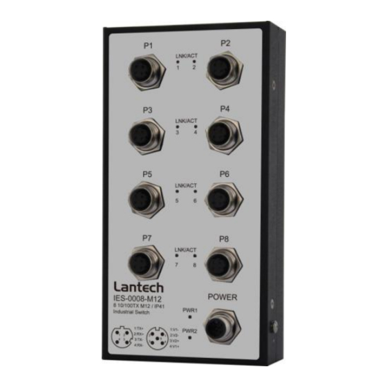
Front Panel The figure shown below is the Front Panel of the Ethernet switch. Front Panel... -
Page 10: Led Indicators
LED Indicators LED indicators located on the front panel display the status of system power, networking and power feeding over Ethernet of the Ethernet switch. Please refer to the following table for further details. Color Description Power input 1 is active PWR1 Green Power input 1 is inactive... -
Page 11: Fast Ethernet Ports
Fast Ethernet Ports Prepare the M12, 4-pole D-Coded Fast Ethernet Port mating cable for Ethernet connection. The M-12 D-coded Fast Ethernet ports are auto-sensing for 10Base-T or 100Base-TX devices connections. Auto MDI/MDIX means that you can connect to another switch or workstation without changing straight through or crossover cabling. ... -
Page 12: Pinouts Of The Power Connector
Pinouts of the Power Connector Prepare the M12, 5-pole A-Coded cable for Ethernet connection. Connect the positive and negative wires to PWR1 (V1+, V1-) and PWR2 (V2+, V2-) as the power pin assignments shown below. Power1 & Power2 Contacts of the M12 Connector Only trained and qualified personnel should be allowed to install or Warning replace this equipment. -
Page 13: Installation
Installation Wall Mounting To hang the Ethernet switch on the wall, please follow the steps below. 1. Prepare the two wall-mount plates and six screws included. 2. Align the screw holes between the wall-mount plates and the unit as the figure illustrated. -
Page 14: Din-Rail Mounting
DIN-Rail Mounting To mount the Ethernet switch to a standards DIN rail, please follow the steps below. 1. Prepare the DIN-rail clip and three screws included. 2. Align the screw holes between the clip and the unit as the figure illustrated. 3. -
Page 15: Grounding The Ethernet Switch
Grounding the Ethernet Switch Follow the instructions below to attach the Ethernet switch to ground. When installing the Ethernet switch, the ground connection must ATTENTION always be made first and disconnected last. 1. Locate and remove the dome screw which has a ground symbol beside it. 2. -
Page 16: Troubleshooting
Troubleshooting Verify that you are using the correct power cord/adapter. Don’t use the power adapter with DC output higher than the rated voltage of the equipment. Or the equipment will be damaged. Select proper cables to construct your network. Please check that you are using the right cables.
Need help?
Do you have a question about the IES-0008-M12 and is the answer not in the manual?
Questions and answers