
Related Manuals for Lantech LGS-2424C


Summary of Contents for Lantech LGS-2424C
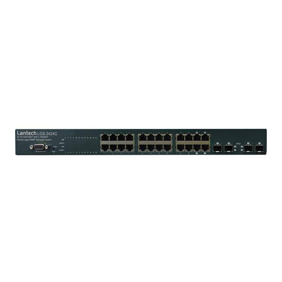
- Page 1 Lantech LGS-2424C 24 10/100/1000T with 4 1000SFP shared cage SNMP Managed Switch User Manual v1.30 Aug 2008...
- Page 2 Release Note 24 10/100/1000T with 4 1000SFP shared cage SNMP Managed Switch Current Update Progress status Version 25/Dec/2006 V1.00 New edit Anson 12/Feb/2007 V1.10 Update Firmware Release 1.10 Anson 12/Dec/2007 V1.20 Update Firmware version 1.05 Anson 04/Aug/2008 V1.30 Re-sort the items of content, update firmware E.C.
- Page 3 FCC Warning This Equipment has been tested and found to comply with the limits for a Class A digital device, pursuant to Part 15 of the FCC rules. These limits are designed to provide reasonable protection against harmful interference in a residential installation. This equipment generates uses and can radiate radio frequency energy and, if not installed and used in accordance with the instructions, may cause harmful interference to radio communications.
-
Page 4: Table Of Contents
Content Chapter 1 Introduction ......................7 1.1 Hardware Features ..................... 7 1.2 Software Feature ......................9 1.3 Package Contents ....................10 Chapter 2 Hardware Description ..................11 2.1 Physical Dimension ....................11 2.2 Front Panel ....................... 11 2.3 Rear Panel........................ 12 2.4 LED Indicators ...................... - Page 5 6.11 LACP Setting ......................31 6.11.1 LACP Status ....................33 6.12 RSTP Configuration ....................35 6.12.1 RSTP Configuration Tab ................35 6.12.2 RSTP Port Configuration ................36 6.12.3 RSTP Status Tab ..................36 6.13 SNMP Setting ......................38 6.14 QoS Configuration ....................40 6.14.1 QoS DSCP Mapping..................
- Page 6 MAC Commands ......................65 VLAN Commands ......................67 Aggr Commands ......................69 LACP Commands ......................69 RSTP Commands ......................70 QoS Commands ......................72 Mirror Commands ......................74 IP Commands ......................... 75 802.1x Commands ......................76 Filter Commands ......................78 IGMP Commands ......................
-
Page 7: Chapter 1 Introduction
Chapter 1 Introduction The 24 10/100/1000T with 4 1000SFP shared cage SNMP Managed Switch is a multi-port switch that can be used to build high-performance switched workgroup networks. It provides wire-speed, Fast Ethernet switching function that allows high-performance, low-cost connection. The Switch features a store-and-forward switching and it can auto-learn and store source address on an 8K-entry MAC address table. - Page 8 14,880pps for Ethernet port Transfer Rate 148,800pps for Fast Ethernet port 1,488,000pps for Gigabit Ethernet port Packet buffer 500Kbytes Jumbo Packet 9600bytes MAC Address Flash ROM 512Kbytes x 2 SRAM 128Kbytes 1000Base-T: 24 x RJ-45 with auto MDI/MDI-X Connector Gigabit fiber: 4 x MINI-GBIC socket; shared with last 4-port RJ-45 Protocol CSMA/CD...
-
Page 9: Software Feature
Compliance with FCC Class A, CE Safety Compliance with UL, cUL, CE/EN60950-1 1.2 Software Feature Management SNMP v1, Telnet, CLI, Web management RFC 1213 MIBII, SNMP MIB RFC 1493 Bridge MIB Port based VLAN VLAN IEEE802.1Q Tag VLAN(256 entries)/VLAN ID (VLAN ID can be assigned from 1 to 4094) Port Trunk 8 Trunk groups... -
Page 10: Package Contents
Login Security Supports IEEE 802.1x Authentication/RADIUS The rate control supports all of packet type and the Bandwidth Control limit rates are 128K~3968Kbps Supports Flow Control for Full-duplex and Back Flow Control Pressure for Half-duplex Up to 1 Trap station, SNMP Trap Cold start, Port link up, Port link down DHCP... -
Page 11: Chapter 2 Hardware Description
Chapter 2 Hardware Description This section mainly describes the hardware of the 24 10/100/1000T with 4 1000SFP shared cage SNMP Managed Switch. 2.1 Physical Dimension The physical dimensions of the 24 10/100/1000T with 4 1000SFP shared cage SNMP Managed Switch is 440mm(W) x 161mm(D) x 44mm(H) 2.2 Front Panel The Front Panel of the 24 10/100/1000T with 4 1000SFP shared cage SNMP Managed Switch consist of 24 x auto-sensing 10/100/1000Mbps Ethernet RJ-45 ports (automatic... -
Page 12: Rear Panel
The appropriate replaceable Mini-GBIC ports are available with 4 Mini-GBIC ports: a variety of different transmitter and receiver types, allowing users to select the appropriate transceiver for each link to provide the required optical reach over the available optical fiber type. Ports 21 ~ 24 are the four combo ports which consist of one RJ-45 port and one mini-GBIC port each. - Page 13 LED Indicators The following table provides descriptions of the LED statuses and meaning. They provide a real-time indication of systematic operation status. Status Description Green Power On Power No power input The port is operating at the speed of 1000 Green 1000Mbps.
-
Page 14: Chapter 3 Hardware Installation
Chapter 3 Hardware Installation 3.1 Desktop Installation Set the switch on a sufficiently large flat space with a power outlet nearby. The surface where you put your Switch should be clean, smooth, level, and sturdy. Make sure there is enough clearance around the Switch to allow attachment of cables, power cord and air circulation. -
Page 15: Cabling
After attaching both mounting plates, position the Switch in the rack by lining up the holes in the plates with the appropriate holes on the rack. Secure the Switch to the rack with a screwdriver and the rack-mounting screws. Mount the Switch in an EIA standard 19-inch Rack Note: For proper ventilation, allows about at least 4 inches (10 cm) of clearance on the front and 3.4 inches (8 cm) on the back of the Switch. - Page 16 To connect the transceiver and LC cable, please follow the steps shown below: First, insert the transceiver into the SFP module. Notice that the triangle mark is the bottom of the module. Transceiver to the SFP module Transceiver Inserted Second, insert the fiber cable of LC connector into the transceiver.
-
Page 17: Chapter 4 Network Application
Chapter 4 Network Application This section provides you a few samples of network topology in which the switch is used. In general, the 24 10/100/1000T with 4 1000SFP shared cage SNMP Managed Switch is designed to be used as a desktop or segment switch. 4.1 Desktop Application The 24 10/100/1000T with 4 1000SFP shared cage SNMP Managed Switch is designed to be a desktop size switch that is an ideal solution for small workgroup. - Page 18 User can connect PCs, workstations, and servers to each other via the 24 10/100/1000T with 4 1000SFP shared cage SNMP Managed Switch. All the devices in this network can communicate with each other. Connecting servers to the backbone switch allow other users to access the data of server.
-
Page 19: Chapter 5 Console Management
Chapter 5 Console Management 5.1 Connecting to the Console Port Use the supplied RS-232 cable to connect a terminal or PC to the console port. The connected terminal or PC must support the terminal emulation program. Connecting the switch to a terminal via RS-232 cable 5.2 Login in the Console Interface When the connection between Switch and PC is ready, turn on the PC and run a terminal emulation program or Hyper Terminal and configure its communication parameters to... - Page 20 The settings of communication parameters After finishing the parameter settings, click “OK“. When the blank screen shows up, type in “root” then press enter button to get into command line mode. Please see below figure for login screen. CLI command interface...
-
Page 21: Cli Management
5.3 CLI Management The system supports console management (CLI command). After you login to the system, you will see a command prompt. CLI command interface 5.4 Commands Level: System - System commands Console - Console commands Port - Port commands - MAC commands VLAN - VLAN commands... - Page 22 Dot1x - Dot1x commands Filter - Filter commands IGMP - IGMP Snooping commands Exit - Logout...
-
Page 23: Chapter 6 Web-Based Management
Chapter 6 Web-Based Management This section introduces the configuration and functions of the Web-Based management. 6.1 About Web-based Management On CPU board of the switch, there is an embedded HTML web site residing in flash memory, which offers advanced management features and allow users to manage the switch from anywhere on the network through a standard browser such as Microsoft Internet Explorer. -
Page 24: System Configuration
Login Interface 6.4 System Configuration The system parameters information as shown below displays the system information and allows the user to configure the other parameters as well. MAC Address: The unique hardware address assigned by manufacturer (default). S/W Version: Displays the Software Version of Kernel. ... -
Page 25: Console Info
the client/switch boots and the lease is 50% or more passed, the client/switch will attempt to renew the lease. At 87.5% of the lease completion, the client/switch will attempt to contact any DHCP server for a new lease. DHCP Enable: Tick the check box to enable DHCP Client Function. ... -
Page 26: Port Configuration
And then, click Refresh to get the new setting information as below: Port Statistics interface 6.7 Port Configuration This page displays the port status of linking, and allows the user to set negotiation mode, to enable flow control and max frame function. ... - Page 27 will drop the frames after excessive collisions. Click Refresh to get the newest status. Port Configuration interface...
-
Page 28: Port Trunk Configuration
6.8 Port Trunk Configuration Port trunk allows multiple links to be bundled together and act as a single physical link to increase throughput. It provides load balancing, and redundancy of links in a switched inter-network. Actually, the link does not have an inherent total bandwidth equal to the sum of its component physical links. -
Page 29: Port Mirroring
6.9 Port Mirroring Analysis Port: Select a port for analyzing other ports. Monitor Rx and TX: Tick the check box for enabling the received/transmitted packets of the port to be monitored. And then, click to apply the configuration. Apply ... -
Page 30: Vlan Port Setting
switch physically. Assign the VLAN ID in number between 1 and 4094. Click add all to tick the 24 check boxes at the same time. Click to clear all of the ticks in the 24 check boxes. clear all ... -
Page 31: Lacp Setting
All: All type of frames. Tagged: Outgoing frames with VLAN-Tagged. After that, click to have the configuration taken effect. Apply Or, click Refresh to reset the configuration before applying. VLAN Port Setting interface 6.11 LACP Setting... - Page 32 The Link Aggregation Control Protocol (LACP) is a computer networking term and is part of IEEE specification 802.3ad that allows bundling several physical ports together to form a single logical channel. LACP allows a network switch to negotiate an automatic bundle by sending LACP packets to the peer.
-
Page 33: Lacp Status
LACP Setting interface 6.11.1 LACP Status When the LACP aggregator has been set up, the LACP status information will display as below. Protocol Active: Displays whether the LACP protocol is active. Partner Port Number: Displays the partner port number which is connecting to this port. - Page 34 aggregate together. LACP Status interface...
-
Page 35: Rstp Configuration
6.12 RSTP Configuration The Rapid Spanning Tree Protocol (RSTP) is an evolution of the Spanning Tree Protocol and provides for faster spanning tree convergence after a topology change. The system also supports STP and the system will automatically detect the connected device that is running STP or RSTP protocol. -
Page 36: Rstp Port Configuration
6.12.2 RSTP Port Configuration Protocol Enable: Enable or disable the RSTP protocol for the port. Edge: Having set the port as an edge port which directly connected to end stations cannot create bridging loop in the network. To configure the port as an edge port, tick the check box. - Page 37 Click Refresh to get the newest configuration information. Also, the RSTP Bridge Overview will display as below. RSTP Bridge Overview Bridge ID: Displays the ID produced by the algorithm of MAC address and priority that is used in the STP/RSTP structure. ...
-
Page 38: Snmp Setting
RSTP Port Status interface 6.13 SNMP Setting Simple Network Management Protocol (SNMP) is the protocol developed to manage... - Page 39 nodes (servers, workstations, routers, switches and hubs etc.) on an IP network. SNMP enables network administrators to manage network performance, find and solve network problems, and plan for network growth. Network management systems learn of problems by receiving traps or change notices from network devices implementing SNMP. SNMP Setting interface ...
-
Page 40: Qos Configuration
6.14 QoS Configuration In this segment, you can configure QoS policy setting, QoS DSCP setting, priority queue service, and QoS Vlan tag. Mode: Select the QoS mode—port, DSCP, or vlan tag. Port Priority: Select the priority level—low, normal, medium, or high. ... -
Page 41: Qos Dscp Mapping
6.14.1 QoS DSCP Mapping Change to Qos DSCP Mapping tab: DSCP [0- 63]: The system provides 0~63 TOS priority level. When the IP packet is received, the system will check the TOS level value in the IP packet that has received. -
Page 42: Priority Queue Service
6.14.2 Priority Queue Service Change to Priority Queue Service tab: You can choose the means for priority queue. There are two radio buttons selection item—„All High Before Low’ & „Weighted Round Robin/WRR’—in each port column. When „All High Before Low’ is selected, the low priority queues will be served before all of the high priority queue services are finished. -
Page 43: Qos Vlan Tag
And then, click to apply the configuration. Apply Or, Click Refesh to reset the configuration before applying. 6.14.3 QoS Vlan Tag You can pull down the selection item from Vlan Tag 0 to Vlan Tag 7 of each port to assign the priority. -
Page 44: Igmp Configuration
QoS VLAN Tag Priority Mapping interface 6.15 IGMP Configuration IGMP Enabled: Tick the check box to enable IGMP function. Router Ports: Tick the check box beside the port number for checking. Unregistered IPMC Flooding enabled: The default state is checked to enable the unregistered IP Multicast flooding. -
Page 45: Igmp Status
And then, click to apply the configuration. Apply Or, Click Refesh to reset the configuration before applying. IGMP Configuration interface 6.15.1 IGMP Status Querier: Displays the status of the querier. Queries transmitted: Displays the amount of the transmitted queries. ... -
Page 46: Rate Limit Configuration
IGMP Status interface 6.16 Rate Limit Configuration Storm Control (Number of frames per second) ICMP Rate: Assign the rate of transmitting packets of ICMP. The rates are in the range of 1K ~ 1024K fps or No limit. ... -
Page 47: Security Configuration
Rate Limit interface 6.17 Security Configuration Source IP Security Mode: Select the source IP mode—Static, DHCP, or Disabled. IP Address: When Mode is set in Static mode, the user has to assign an IP address manually. IP Mask: When Mode is set in Static mode, the user has to assign the IP mask manually. -
Page 48: 802.1X Configuration
And then, click to apply the configuration. Apply Or, Click Refesh to reset the configuration before applying. Filter Configuration interface 6.18 802.1X Configuration IEEE 802.1X is an IEEE standard for port-based Network Access Control; it is part of the IEEE 802 (802.1) group of protocols. - Page 49 unauthorized access to the network at the data link layer. Mode: Disable or enable IEEE 802.1x authentication. RADIUS IP: Assign the Radius Server IP address. RADIUS UDP Port: Assign the UDP destination port for authentication requests to the specified Radius Server.
-
Page 50: 802.1X Parameters
802.1X Configuration interface 6.18.1 802.1X Parameters Click on the tab of 802.1X Parameters to change to configure the 802.1X Parameters page. Reauthentication Enable: Enable the re-authentication mode. Reauthentication Period (1~3600 seconds): Set the period of time after which clients connected must be re-authenticated. -
Page 51: 802.1X Statistics
And then, click to apply the configuration. Apply Or, click Refresh to reset the configuration before applying. 802.1X Parameters interface 6.18.2 802.1X Statistics Click the tab of 802.1X Statistics to change to the 802.1X Statistics page to view the detail information. -
Page 52: Mac Address Table Control
802.1X Statistics interface 6.19 MAC Address Table Control MAC Address Entry No: The index of the MAC address table. MAC Address: The MAC address of the entry. Port: Displays the port number from which the MAC address was learned. ... -
Page 53: Static Mac Address Entries In Permanent Table
Dump MAC Address Table interface 6.19.1 Static MAC Address Entries in Permanent Table You can add/delete MAC address entries manually to maintain the MAC address table. Click Refesh to get the newest information. -
Page 54: Tftp Firmware Upload
Static MAC Address Entries in Permanent Table interface 6.20 TFTP Firmware Upload It provides the functions that allow you to upgrade the switch firmware. Before upgrading, make sure the TFTP server is ready and the firmware image is located on the TFTP server. -
Page 55: Tftp Firmware Backup
6.20.1 TFTP Firmware Backup It provides the functions that allow user to backup the switch firmware. Before doing that, make sure the TFTP server is ready. TFTP Server IP Address: Type in your TFTP server IP. Firmware File Name: Type in the name of the firmware image file. ... -
Page 56: Tftp Configuration Backup
6.20.3 TFTP Configuration Backup It provides the functions that allow user to backup the switch configuration. Before doing that, make sure the TFTP server is ready. TFTP Server IP Address: Type in your TFTP server IP. Backup File Name: Type in the name of the backup image file. ... -
Page 57: Configuration Upload/Download
6.21.1 Configuration Upload/Download The system provides the Web GUI configuration file transfer function which would allow user to backup and restore the switch configuration. Click Browse to locate the file. And then, press Upload to upload the file. Configuration Upload interface ... -
Page 58: Factory Default
6.22 Factory Default Reset the switch to default configuration. Click Yes to reset all of the configurations to the default value. Or click KeepIP to reset all of the configurations to the default value except IP address. Factory Default interface 6.23 Warm Restart Reboot the switch in software reset to have the configurations taken effect. -
Page 59: Troubleshooting
Troubleshooting This section is intended to help user solve the most common problems on the 24 10/100/1000T with 4 1000SFP shared cage SNMP Managed Switch. Incorrect connections The switch port can automatically detect straight or crossover cable when user link switch with other Ethernet device. - Page 60 It is important to make sure that you have a valid network topology. Common topology faults include excessive cable length and too many repeaters (hubs) between end nodes. In addition, you should make sure that your network topology contains no data path loops.
-
Page 61: Appendix A- Command Sets
Appendix A- Command Sets System Commands Commands Description Example configuration [all] Show system name, software system>configuration version, hardware version and management system>configuration all MAC address. Optionally show the full configuration restore default [keepip] Restore factory default system>restore default configuration. system>restore default keepip Restore to default without changing the current IP name... -
Page 62: Console Commands
SNMP (default: Show SNMP mode). Trap [<IP Address>] Set or show SNMP traps system>trap destination. system>trap 192.168.16.66 <IP Address>: IP address to send traps to. (default: Show trap configuration) readcommunity Set or show SNMP read system>readcommunity [<community string>] community string. system>readcommunity aaa [<community string>]: New community string. -
Page 63: Port Commands
[<password>] The empty string ("") disables the password check. console>password aaa [<password>]: Password string of up to 16 characters. timeout [<timeout>] Set or show the console inactivity console>timeout timeout in seconds. The value zero disables timeout. console>timeout 100 [<timeout>]: Timeout value in seconds, 0,60-10000. - Page 64 mode (Default: Show configured port>1-20 1000fdx and current mode). 10hdx: 10 Mbit/s, half duplex. 10fdx: 10 Mbit/s, full duplex. 100hdx: 100 Mbit/s, half duplex. 100fdx: 100 Mbit/s, full duplex. 1000fdx: 1 Gbit/s, full duplex. auto: Auto negotiation of speed and duplex. flow control Set or show flow control mode for port>flow control...
-
Page 65: Mac Commands
port>statistics 2 [<portlist>]: Port list (default: All ports). port>statistics clear [clear]: Clear port statistics (default: Show statistics). excessive collisions Description: port>excessive collisions drop [enable|disable] Enable or disable drop of frames drop when excessive collisions occur in half duplex mode. port> excessive collisions drop enable [enable|disable]: Enable/disable frame drop (default: Show... - Page 66 [<vid>] <macaddress>: MAC address, 12 digit hex string, optionally separated with dashes or colons (e.g. 010203ABCDEF or 01-02-03-AB-CD-EF or 01:02:03:AB:CD:EF). [<vid>]: VLAN ID (default: All). lookup <macaddress> Lookup MAC address and VLAN mac>lookup 000000000001 2 [<vid>] <macaddress>: MAC address, 12 digit hex string, optionally separated with dashes or colons (e.g.
-
Page 67: Vlan Commands
VLAN Commands Commands Description Example configuration Show the VLAN aware mode, port vlan>configuration [<portlist>] VLAN ID and accepted frame type for the port and the permanently vlan>configuration 2 stored VLAN table. <vidlist> Add VLAN entry and include ports vlan>add 2 1 [<portlist>] in member set. - Page 68 [enable|disable]: Enable/disable VLAN awareness (default: Show awareness). pvid [<portlist>] Set or show the port VLAN ID. vlan>pvid 1 2 [<vid>|none] Untagged frames received on the port will be classified to this VLAN vlan>pvid all 2 ID. Frames classified to this VLAN ID will be sent untagged on the port.
-
Page 69: Aggr Commands
Aggr Commands Commands Description Example configuration Shows the aggregation groups and aggr>configuration the aggregation mode. <portlist> Add link aggregation group aggr>add 1-4 including ports. <portlist>: Aggregation port list. delete <portlist> Delete link aggregation group. aggr>delete 1-4 <portlist>: Port list. Aggregations including any of the ports will be deleted. -
Page 70: Rstp Commands
ports). mode [<portlist>] Enable or disable the LACP lacp>mode 3 enable [enable|disable] protocol on ports <portlist>. lacp>mode 1-4 enable [<portlist>]: Port list (Default: All ports). lacp>mode 1-4 disable [enable|disable]: Enable or disable. [<portlist>] Set the LACP key on ports lacp>key 1 200 [<key>|auto] <portlist>. - Page 71 This provides for 16 distinct values: 0, 4096, 8192, 12288, 16384, 20480, 24576, 28672, 32768, 36864, 40960, 45056, 49152, 53248, 57344 and 61440. hellotime [<secs>] Set or show the RSTP System rstp>hellotime Hello time. rstp>hellotime 1 [<secs>]: Number between 1 - 10 (default is 2) maxage [<hops>]...
-
Page 72: Qos Commands
protocol on aggregated links. [enable|disable]: Enable or disable. edge [enable|disable] Expect the port to be an edge port rstp>edge 1 disable (an end station) or a link to another STP device. rstp>edge 1 enable [enable|disable]: End-station or rstp>edge all enable bridge. - Page 73 priority and DSCP mapping for the port. [<portlist>]: Port list (default: All ports). mode [<portlist>] Set or show the QoS mode for the qos>mode [tag|port|diffserv] port. qos>mode 1-4 [<portlist>]: Port list (default: All ports). qos>mode 1 tag [tag|port|diffserv]: Enable tag, port or IP differentiated services class qos>mode all tag of service for the port (default:...
-
Page 74: Mirror Commands
(default: Show class). qos>diffserv 2 normal qos>diffserv 3 low priority queue service Set or show weighted rate ratio qos>priority queue service [<portlist>] [all high before low|<low [<portlist>]: Port list (default: All wrr:normal wrr ports) qos>priority queue service :medium wrr:high 1-4 all high before low wrr>] [<all high before low>|<low:normal:medium:high>]:... -
Page 75: Ip Commands
IP Commands Commands Description Example configuration Show IP configured IP address, ip>configuration mask, gateway, VLAN ID and mode. status Show current IP status. ip>status setup [<ipaddress> Setup or show IP configuration. ip>setup 192.168.16.3 [<ipmask> 255.255.255.0 192.168.16.10 1 [<ipgateway>]]] [<vid>] [<ipaddress>]: IP address. (default: Show IP configuration) [<ipmask>]: IP subnet mask (default: Subnet mask for address... -
Page 76: 802.1X Commands
DHCP (default: Show DHCP mode). tftp [enable|disable] Activate or deactivate the TFTP ip>tftp enable protocol. [enable|disable]: Enable/disable TFTP (default: Show TFTP mode). tftpget server-ip Fetch file from server-ip via the ip>tftpget 192.168.16.66 3.wrp filename TFTP protocol and store in flash. The content of the file will determine if it is a runtime image or a configuration file. - Page 77 mode [enable|disable] Enable or disable 802.1X process dot1x>mode enable for the switch. [enable|disable]: new mode (default: Show current configuration). state [<portlist>] Set or show the 802.1X state for dot1x>state 1 auto [Auto|ForceAuthorized the port. |ForceUnauthorized] dot1x>state 1 forceauthorized [<portlist>]: Port list (default: All ports).
-
Page 78: Filter Commands
configuration) statistics [<portlist>] Show 802.1X statistics for the port. dot1x>statistics [<portlist>]: Port list (default: All dot1x>statistics 1 ports). reauthenticate Refresh (restart) 802.1X dot1x>reauthenticate 1 now [<portlist>] [now] authentication process for the port by setting reAuthenticate TRUE. dot1x>reauthenticate 1 [<portlist>]: Port list (default: All ports). -
Page 79: Igmp Commands
ports). source ip [<portlist>] Set or show the valid source IP filter>source IP 192.168.16.11 [all|dhcp|<ipaddress> address for the port. 255.255.255.0 [<ipmask>]] [<portlist>] : Port list (default: All filter>source ip dhcp ports). [all|dhcp|<ipaddress> [<ipmask>]]: filter>source ip all Allow all IP addresses, the IP address from DHCP or static IP address configuration (default: Show Filter source IP). - Page 80 and statistics. groups <vidlist> Show IGMP groups for given igmp>group 1 VLANs. mode [enable|disable] Set or show global IGMP mode. igmp>mode enable (default: Show current mode) state <vidlist> Set or Show IGMP state per igmp>state 1 enable [enable|disable] VLAN. (default: Show IGMP state) querier <vidlist>...
Need help?
Do you have a question about the LGS-2424C and is the answer not in the manual?
Questions and answers