
Related Manuals for Omega UWPC-2-NEMA


Summary of Contents for Omega UWPC-2-NEMA
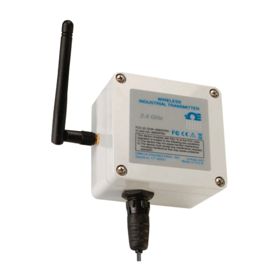
- Page 1 MADE IN User’ s Guide Shop online at omega.com e-mail: info@omega.com or latest product manuals: omegamanual.info UWPC-2-NEM Wireless Process Voltage/Current Transmitter...
- Page 2 Online Service Internet e-mail ® omega.com info@omega.com Servicing North merica: U.S.A.: Omega Engineering, Inc., One Omega Drive, P.O. Box 4047 ISO 9001 Certified Stamford, CT 06907-0047 USA Toll Free: 1-800-826-6342 TEL: (203) 359-1660 FAX: (203) 359-7700 e-mail: info@omega.com Canada: 976 Bergar...
-
Page 3: Table Of Contents
UWPC-2-NEM Wireless Process Voltage/Current Transmitter Table of Contents Section ......................Page Section 1 Introduction ................... 1-1 1.1 Precautions ....................1-1 1.2 Statement on FCC and CE ............... 1-2 1.3 General Description and System Components ........1-2 Section 2 Hardware ....................2-1 2.1 Unpacking and Inspection ............... - Page 4 UWPC-2-NEM Wireless Process Voltage/Current Transmitter List of Figures Section Figure Description ............... Page Section 3.1 Main Transmitter Board ........... 3-1 Section 4.2.2 Software - Welcome Screen ........4-1 Section 4.2.2 Software - Select Installation Screen ....... 4-2 Section 4.2.2 Software - Confirm Installation Screen ....4-2 Section 4.2.2 Software –...
-
Page 5: Section 1 Introduction
Introduction Section 1 - Introduction Please read this manual completely before installing and operating your wireless end device and receiver system. It’s important read and follow all notes, cautions, warnings and safety precautions before operating this device. “Device” refers to your transmitter or receiver unit. 1.1 Precautions •... -
Page 6: Statement On Fcc And Ce
1.2.2 CE Marking It is the policy of OMEGA to comply with all worldwide safety and EMI/EMC regulations that apply. OMEGA is constantly pursuing certification of its products to the European New Approach Directives. OMEGA will add the CE mark to every appropriate device upon certification. -
Page 7: Section 2 Hardware
2.2 Included Items The following items are supplied in the box. • 1 UWPC-2-NEMA transmitter • 1 User’s Guide • Measurement/Data Logging Software • 3.6V Lithium Battery... -
Page 8: Section 3 Operation
Operation Section 3 - Operation 3.1 Main Transmitter Board STATUS LOW BATTERY ON/OFF SETUP Figure 3-1. Main Transmitter Board... -
Page 9: Section 4 Software
The following program files are included on the TC-Central User Software CD supplied with your Receiver. These files can also be downloaded from the omega.com website should you misplace your CD. • End Device Setup Utility Software • Receiver/Transceiver Setup Utility Software •... -
Page 10: Section 4.2.2 4-2 Software - Select Installation Screen
From this screen you select the folder were you want the program files installed on your PC. The default setting will install the software under your “Program” folders in a new folder named “Omega” To continue with installing the program click the “Next >” button. -
Page 11: Section 4.2.2 4-4 Software – License Agreement Screen
Software Figure 4-4. Software - License Agreement Screen From this screen you must select “Agree” to continue installing your program. After making your selection click the “Next >” button. The setup wizard will now install the software. Figure 4-5. Software - Installation Complete Screen Congratulations! You have just successfully installed the TC-Central Program on your PC. -
Page 12: Section 5 End Device Operation
End Device Operation Section 5 - End Device Operation 5.1 Setup and Configuration 5.1.1 Connecting your device Connect the USB cable to your connector/transmitter unit and also to an available USB port on your computer. See figure below. This cable was provided in the box with your receiver unit. - Page 13 End Device Operation Channel Number This sets a unique address number into your transmitter. Later, when you set up your measurement software you will again set channel numbers to receive readings from the corresponding unit(s). Each unit must be set for a different channel number for your system to operate correctly.
-
Page 14: Section 5.1.4 5-2 Main Transmitter Board
To launch the End Device setup utility program on your PC begin by accessing the “Programs” list under your “Start Menu”. Scroll through the list of to find the Omega “TC-Central” folder, then select the End Device Configuration Program. Figure 5-3. Launch Setup Utility... -
Page 15: Section 5.1.4 5-4 Utility Program - Welcome
End Device Operation STEP 3. Programming your settings into your End Device Figure 5-4. Utility Program - Welcome Screen After starting the setup utility program this will be the first screen you will see. Click the “Next >” button to proceed and continue setting up your End Device. Each screen will provide instruction details on how to proceed. -
Page 16: Section 5.1.4 5-6 Utility Program – Setup Transmitter
End Device Operation Figure 5-6. Utility Program - Setup Transmitter Screen If you have not already placed your End Device into the “Setup” mode you should do this now before continuing. After your unit has been placed into the “Setup” mode click the “Next >” button to proceed and continue setting up your unit. -
Page 17: Section 5.1.4 5-8 Utility Program – Choose Options
End Device Operation Figure 5-8. Utility Program - Choose Options Screen From this screen you will select the main operating settings for your end device. (Note: Each end device must have a different address number for proper operation). After making your selections click the “Next >” button to proceed and program your settings into your unit. -
Page 18: Mounting Installation
End Device Operation 5.2 Mounting, Installation and ntenna connection 5.2.1 Mounting 4.3 (0.17) MOUNTING HOLE 55.0 (2.17) 82.0 (3.23) 70.0 (2.76) 50.0 (1.97) 80.0 (3.15) DIMENSIONS mm (in) Figure 5-10. Mounting When mounting your end device, care should be taken to make sure it is as far away from any metal objects. - Page 19 End Device Operation In order to achieve maximum range, the football-shaped path in which radio waves travel must be free of all obstructions. Obstacles in the path (especially metal) will decrease the communication range between your End Device and receiver. Also, If the antennas are mounted just barely off the ground, over half of the Fresnel zone ends up being obstructed by the earth resulting in significant reduction in range.
-
Page 20: Battery Replacement
Figure 5-12. Battery Replacement Your End Device is equipped with a “C” size lithium power cell assembly. Omega Part Number: UWTC-BATT-C. To install a replacement battery assembly follow steps outlined here. A. Remove the two screws that secure the main circuit board assembly. -
Page 21: Section 5.3.2 5-13 Fresnel Zone
End Device Operation C UTION: Installing your end device in an application were the unit will be exposed to ambient temperatures above or below the operating limits specified in this manual will damage your unit and cause the unit to malfunction and produce incorrect operation. 5.3.2 Installation When installing your receiver it is important to position your device in such a way as to optimize the antenna location within what’s known as the “Fresnel... -
Page 22: Input Connections
End Device Operation 5.3.3 Antenna Connection Your receiver has been shipped to you a high gain antenna already attached. In some cases, a short RF cable may be used to connect an antenna to your end device. Please note that RF extension cables will always add some loss to the transmitting signal strength. -
Page 23: Section 6 System Operation
6.2 RF Communication Basics The Model UWPC-2-NEMA sends wireless transmissions to a receiver. The receiver checks the incoming data for accuracy and processes this data for use by the measurement software on your PC. Radio signals are electromagnetic waves, hence the signal becomes weaker the further it travels. -
Page 24: Environment/Operating Conditions
6.4 Environment/Operating Conditions 6.4.1 Environment Omega’s NEMA wireless end devices and receiver units have been designed to be fixed and operated in both indoor and outdoor environments; they are also weather-resistant. Care should be taken to prevent the components of your wireless system from being exposed to toxic chemicals and extreme cold or hot temperature that are outside the specifications listed in this manual. -
Page 25: Transmit Rate Vs. Battery Life
The table below give some estimates on how long the battery should last vs. the transmit rate you selected when you setup your end device and under normal operating conditions. For Model: UWPC-2-NEMA Transmit Time Estimated attery Life 1 Sample/2 Seconds... -
Page 26: Section 7 Service And Calibration
Service and Calibration Section 7 – Service & Calibration Your UWPC-2-NEMA Wireless Process Transmitter has been built and factory calibrated to meet or exceed the specifications listed here in this manual. Information is provided below on how to have your unit service. -
Page 27: Section 8 Specifications
Specifications Section 8 – Specifications Input Range: 0-1 Vdc, 0-5 Vdc, 0-10 Vdc, or 4-20mA Accuracy: ±0.04% of range Input Connection: Panel connector (mating connector supplied) Computer Interface: USB (for setup only) Transmit Sample Rate: Programmable, 1 sample/every 2 min. to 1 sample/every 2 sec. -
Page 28: Section 9 Approvals, Regulatory Compliance
Approvals, Regulatory Compliance Section 9 – Approvals, Regulatory Compliance NOT : ll approvals outlined in this manual are based on testing that was done with antennas that are supplied with your Wireless Series System Components. Removing and or installing a different antenna will void the product compliance demonstrated in these documents. - Page 29 UWPC-2-NEM Wireless Process Voltage/Current Transmitter NOTES:...
- Page 30 UWPC-2-NEM Wireless Process Voltage/Current Transmitter NOTES:...
- Page 31 W RR NTY/DISCL IMER OMEG ENGINEERING, INC. warrants this unit to be free of defects in materials and workmanship for a period of 13 months from date of purchase. OMEG ’s W RR NTY adds an additional one (1) month grace period to the normal one (1) year product warranty to cover handling and shipping time.
- Page 32 Where Do I Find Everything I Need for Process Measurement and Control? OMEG …Of Course! Shop online at omega.com TEMPER TURE Thermocouple, RTD & Thermistor Probes, Connectors, Panels & Assemblies Wire: Thermocouple, RTD & Thermistor Calibrators & Ice Point References Recorders, Controllers &...
Need help?
Do you have a question about the UWPC-2-NEMA and is the answer not in the manual?
Questions and answers