Table of Contents
Advertisement
Quick Links
U.S.A.
Headquarters:
The information contained in this document is believed to be correct, but OMEGA accepts no liability for any errors it contains, and reserves the
right to alter specifications without notice.
OMEGA ENGINEERING, INC. warrants this unit to be free of defects in materials and workmanship for a period of 13 months
from date of purchase. OMEGA's WARRANTY adds an additional one (1) month grace period to the normal one (1) year product
warranty to cover handling and shipping time. This ensures that OMEGA's customers receive maximum coverage on each product.
If the unit malfunctions, it must be returned to the factory for evaluation. OMEGA's Customer Service Department will issue an
Authorized Return (AR) number immediately upon phone or written request. Upon examination by OMEGA, if the unit is found to
be defective, it will be repaired or replaced at no charge. OMEGA's WARRANTY does not apply to defects resulting from any action
of the purchaser, including but not limited to mishandling, improper interfacing, operation outside of design limits, improper
repair, or unauthorized modification. This WARRANTY is VOID if the unit shows evidence of having been tampered with or shows
evidence of having been damaged as a result of excessive corrosion; or current, heat, moisture or vibration; improper specifica-
tion; misapplication; misuse or other operating conditions outside of OMEGA's control. Components in which wear is not war-
ranted, include but are not limited to contact points, fuses, and triacs.
OMEGA is pleased to offer suggestions on the use of its various products. However, OMEGA neither assumes respon-
sibility for any omissions or errors nor assumes liability for any damages that result from the use of its products
in accordance with information provided by OMEGA, either verbal or written. OMEGA warrants only that the parts
manufactured by the company will be as specified and free of defects. OMEGA MAKES NO OTHER WARRANTIES
OR REPRESENTATIONS OF ANY KIND WHATSOEVER, EXPRESSED OR IMPLIED, EXCEPT THAT OF TITLE, AND ALL
IMPLIED WARRANTIES INCLUDING ANY WARRANTY OF MERCHANTABILITY AND FITNESS FOR A PARTICULAR
PURPOSE ARE HEREBY DISCLAIMED. LIMITATION OF LIABILITY: The remedies of purchaser set forth herein are
exclusive, and the total liability of OMEGA with respect to this order, whether based on contract, warranty, negli-
gence, indemnification, strict liability or otherwise, shall not exceed the purchase price of the component upon which
liability is based. In no event shall OMEGA be liable for consequential, incidental or special damages.
CONDITIONS: Equipment sold by OMEGA is not intended to be used, nor shall it be used: (1) as a "Basic Component" under 10
CFR 21 (NRC), used in or with any nuclear installation or activity; or (2) in medical applications or used on humans. Should any
Product(s) be used in or with any nuclear installation or activity, medical application, used on humans, or misused in any way,
OMEGA assumes no responsibility as set forth in our basic WARRANTY / DISCLAIMER language, and, additionally, purchaser will
indemnify OMEGA and hold OMEGA harmless from any liability or damage whatsoever arising out of the use of the Product(s) in
such a manner.
Direct all warranty and repair requests/inquiries to the OMEGA Customer Service Department. BEFORE RETURNING ANY
PRODUCT(S) TO OMEGA, PURCHASER MUST OBTAIN AN AUTHORIZED RETURN (AR) NUMBER FROM OMEGA'S CUSTOMER
SERVICE DEPARTMENT (IN ORDER TO AVOID PROCESSING DELAYS). The assigned AR number should then be marked on the
outside of the return package and on any correspondence.
The purchaser is responsible for shipping charges, freight, insurance and proper packaging to prevent breakage in transit.
FOR WARRANTY RETURNS, please have the following infor-
mation available BEFORE contacting OMEGA:
1. Purchase Order number under which the product was
PURCHASED,
2. Model and serial number of the product under warranty, and
3. Repair instructions and/or specific problems relative to the
product.
OMEGA's policy is to make running changes, not model changes, whenever an improvement is possible. This affords our customers the latest in technology and
engineering. OMEGA is a registered trademark of OMEGA ENGINEERING, INC.
© Copyright 2017 OMEGA ENGINEERING, INC. All rights reserved. This document may not be copied, photocopied, reproduced, translated, or reduced to any electronic
medium or machine-readable form, in whole or in part, without the prior written consent of OMEGA ENGINEERING, INC.
omega.com info@omega.com
Servicing North America:
Omega Engineering, Inc.
Toll-Free: 1-800-826-6342 (USA & Canada only)
Customer Service: 1-800-622-2378 (USA & Canada only)
Engineering Service: 1-800-872-9436 (USA & Canada only)
Tel: (203) 359-1660
e-mail: info@omega.com
For Other Locations Visit omega.com/worldwide
WARRANTY/DISCLAIMER
RETURN REQUESTS / INQUIRIES
Fax: (203) 359-7700
FOR NON-WARRANTY REPAIRS, consult OMEGA for current
repair charges. Have the following information available BEFORE
contacting OMEGA:
1. Purchase Order number to cover the COST of the repair,
2. Model and serial number of the product, and
3. Repair instructions and/or specific problems relative to the
product.
MQS4432/1017
Advertisement
Table of Contents

Related Manuals for Omega UWTC Series


Summary of Contents for Omega UWTC Series
- Page 1 Fax: (203) 359-7700 e-mail: info@omega.com For Other Locations Visit omega.com/worldwide The information contained in this document is believed to be correct, but OMEGA accepts no liability for any errors it contains, and reserves the right to alter specifications without notice. WARRANTY/DISCLAIMER OMEGA ENGINEERING, INC.
- Page 2 For complete product manual: www.omega.com/manualpdf/M4432.pdf Shop online at omega.com e-mail: info@omega.com For latest product manuals: www.omegamanual.info UWTC/UWRTD SERIES The Smart Connector Wireless Thermocouple/RTD Connector/Transmitter & Receiver...
-
Page 3: Table Of Contents
UWTC/UWRTD SERIES Quick Start TABLE OF CONTENTS SECTION PAGE Section 1 - Introduction ......................1 Section 2 - Product Labels ......................2 Section 3 - Setup Instructions ....................3 Section 4 - Product Labels ......................5 Section 5 - Transmitter Operation ................... 6 Section 6 - Connector Operation ..................... - Page 4 UWTC/UWRTD SERIES Quick Start LIST OF FIGURES LIST OF FIGURES Section Description Page Section 1 Introduction ....................1 Precautions ....................1 Safety Warnings and IEC Symbols ............1 Section 2 Product Labeling ..................... 2 Section 3 Setup Instructions ..................3 UWTC/UWRTD Setup Procedure ............3 1.
-
Page 5: Section 1 - Introduction
Introduction Section 1 - Introduction Please read this manual completely before installing and operating your wireless connector/transmitter and receiver system. It’s important to read and follow all notes, cautions, warnings and safety precautions before operating this device. “Device” refers to your connector/transmitter or receiver unit. Precautions •... -
Page 6: Section 2 - Product Labels
1) This device may not cause harmful interference; 2) This device must accept any interference received, 12/22/11 including interference that may cause undesired operation. L-1660UWTCRecLabel.eps OMEGA ENGINEERING, INC. omega.com Made in U.S.A. Stamford, CT 06907 Transmitter Front Label (NEMA) TRANSPARENT... -
Page 7: Section 3 - Setup Instructions
Setup Instructions Section 3 – Setup Instructions UWTC/UWRTD Setup Procedure: It is important that you read this manual completely and follow all safety precautions before operating this instrument. 1. Install Software a. Download and install the free software that's available for your UWTC Series receiver. -
Page 8: Configure Receiver
Setup Instructions e. Exit the "SETUP" mode Once you have successfully programmed your connector/transmitter you can disconnect the USB cable and press "SETUP" button on the device once to exit the "SETUP" mode. 4. Configure Receiver UWTC-REC3 Users: Refer to Manual M4620 for configuration of this UWTC receiver. -
Page 9: Section 4 - Product Labels
Software Section 4 – Software Channel Display Box Screen ① Thermocouple Type This box indicates the type of thermocouple sensor that your connector/-transmitter has been programmed to operate with. As a default the thermocouple color codes have been set to the ANSI color codes. You can change these to IEC color codes, see section 3.5.2 ②... -
Page 10: Section 5 - Transmitter Operation
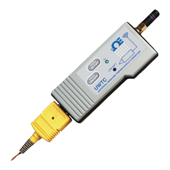
Transmitter Operation Section 5 – Transmitter/Connector Operation PRESS SETUP ® PRESS ON/OFF LOW BATT UWTC UNIVERSAL WIRELESS THERMOCOUPLE CONNECTOR Thermocouple Connector (UWTC-1, UWTC-2) PRESS SETUP ® PRESS ON/OFF LOW BATT UWRTD UNIVERSAL WIRELESS RTD CONNECTOR RTD WIRING DETAIL RTD Connector (UWRTD-1, UWRTD-2) (1) “ON/OFF”... -
Page 11: Section 6 - Connector Operation
Connector Operation Section 6 – Connector Operation Industrial Probe (Thermocouple Versions) UWTC-NB9, UWTC-NB9-NEMA, UWTC-2-NEMA + TC INPUT NOT USED – TC INPUT Thermocouple Version Industrial Probe (RTD Versions) UWRTD-NB9, UWRTD-NB9-NEMA, UWRTD-2-NEMA RTD WIRING DETAIL RTD Version (1) “SETUP” Button (2) “ON/OFF” Button (3) Transmit Indicator (4) Battery Indicator (5) USB Port... - Page 12 Connector Operation SETUP PRESS BUTTON SETUP ® ON/OFF PRESS BUTTON ON/OFF LOW BATT UWTC UNIVERSAL WIRELESS THERMOCOUPLE CONNECTOR Setup Mode Button Operation (1.) “PRESS ON/OFF” The “PRESS ON/OFF” button on the front of your connector/transmitter is used to turn your unit “ON” or “OFF” (2.) “PRESS SETUP”...
-
Page 13: Section 7 - Battery Installation
– Battery Replacement UWTC-1, UWTC-2, UWRTD-1, UWRTD-2 Battery Replacement Your NB9 is equipped with a “C” size lithium power cell assembly. Omega Part Number: UWTC-BATT-NB. To install replacement battery assembly follow steps outlined here. A. Remove the two screws that secure... -
Page 14: Section 8 - Receiver Operation
Receiver Operation Section 8 - Receiver Operation UWTC-REC1 (1) Antenna (2) USB Port (mini-B) (3) Indicator Lights UWTC SERIES WIRELESS RF RECEIVER 2.4 GHz ® FCC ID: OUR–XBEEPRO IC #4214A–XBEEPRO This device complies with Part 15 of the FCC rules. - Page 15 (2) Indicator Lights (3) Power LED (4) DC Power Jack POWER (5) Reset TRANSMIT (6) Ethernet Connection (RJ45) OMEGA UWTC SERIES 2.4 GHz Omega Engineering Inc. Stamford, CT 06907 omega.com Made in USA UWTC-REC3 SIDE VIEW DIAGNOSTICS NETWORK LINK ACTIVITY...
- Page 16 Receiver Operation Section 8 - Receiver Operation Cont. UWTC-REC1-NEMA (1) Antenna (2) USB NEMA 4X Connector Sealing Cap (3) USB NEMA 4X Connector Cable (4) Indicator Lights Receiver Operation - UWTC-REC1-NEMA, UWTC-REC1-915-NEMA UWTC-REC2--D-TC-NEMA (1) Antenna (2) USB NEMA 4X Connector Sealing Cap (3) USB NEMA 4X Connector Cable (4) Indicator Lights (5) 8 Pin Analog I/O...
- Page 17 Receiver Operation Section 8 - Receiver Operation Cont. UWTC-REC2-D-*-NEMA (1) Antenna (2) USB NEMA 4X Connector Sealing (3) USB NEMA 4X Connector Cable (4) Indicator Lights (5) 8 Pin Analog I/O Waterproof Cable *: V1, V2, MA Units. Cable Configuration: Green Wire: Analog Output (–) White Wire: Analog Output (+) Orange Wire: Alarm Power...
-
Page 18: Section 9 - Receiver Connections
Receiver Connections Section 9 - Receiver Connections ANTENNA ANALOG JACK OUTPUT CONNECTOR POWER/ALARM CONNECTOR POWER LED 12-24 Vdc @ 250 mA RECIEVE LED + POWER SUPPLY STATUS LED – POWER SUPPLY STATUS STATUS Receiver Operation - UWTC-REC4 Power Supply Connection ANALOG OUTPUT - 4 (–) ANALOG OUTPUT - 4 (+) ANALOG OUTPUT - 3 (–) - Page 19 Receiver Connection Section 9 - Receiver Connection Cont. 4-20 mA ANALOG OUTPUT 0-5 Vdc ANALOG OUTPUT INTO PLC OR DATA LOGGER INTO PLC OR DATA LOGGER – – – 12 - 24 Vdc FROM HOST INSTRUMENT – STATUS STATUS 24 Vdc POWER SUPPLY 4-20 mA Output Example Voltage Output Example...
- Page 20 Receiver Connection Section 9 - Receiver Connection Cont. 1N4004* – 0-24 VDC POWER – SUPPLY ALARM RELAY 300 mA MAX *DIODE REQUIRED FOR MAGNETIC RELAYS. NOT REQIRED FOR FOR SOLID STATE RELAYS, OR MAGNETIC RELAYS WITH INTERNAL DIODE. DRIVING A RELAY OR LOW IMPEDANCE INPUT (OPEN DRAIN) –...
Need help?
Do you have a question about the UWTC Series and is the answer not in the manual?
Questions and answers
how to setup for process temp and not ambient
To set up the Omega UWTC Series for process temperature measurement instead of ambient temperature:
1. Install the TC Central software on your computer.
2. Install the USB drivers by connecting the UWTC receiver to your PC using the provided USB cable.
3. Configure the display box:
- Enter a reference name in the “Description” field.
- Assign an address number that matches the corresponding connector/transmitter.
4. Ensure the thermocouple or RTD sensor is connected properly to measure the process temperature.
5. The process temperature will be shown in the “Process” field, which reflects the actual measurement from the sensor.
6. Use the “Options” button to access and adjust channel configuration if needed.
Make sure the sensor is positioned to measure the desired process temperature, not the ambient temperature inside the transmitter.
This answer is automatically generated