Precor Discovery Plate Loaded Line Assembly Manual
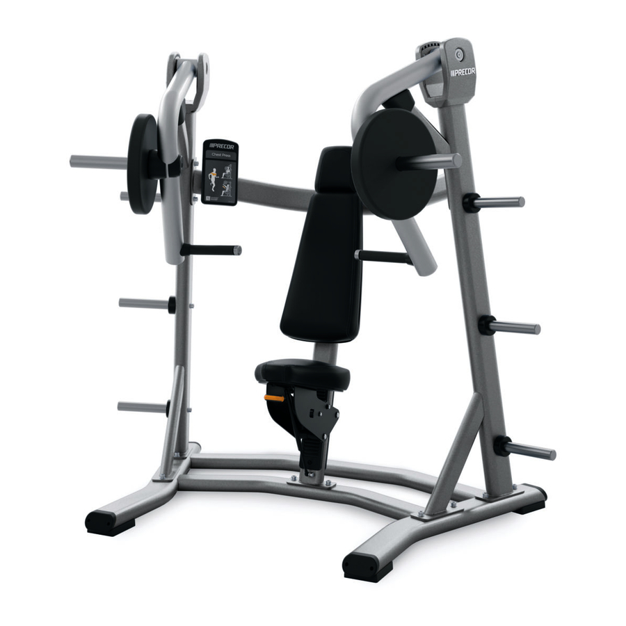
Incline press
Hide thumbs
Also See for Discovery Plate Loaded Line:
- Assembly manual (40 pages) ,
- Owner's manual (36 pages) ,
- Owner's manual (36 pages)
Table of Contents
Advertisement
Available languages
Available languages
Quick Links
Advertisement
Chapters
Table of Contents

Related Manuals for Precor Discovery Plate Loaded Line


Summary of Contents for Precor Discovery Plate Loaded Line
- Page 1 Handboek Discovery Plate Loaded™ Line...
-
Page 3: Belangrijke Veiligheidsrichtlijnen Voor Eigenaren
C-gecertificeerde machines volgens EN957 -1/2-normen. Neem contact op Zorg ervoor dat het apparaat stabiel is en op een stevige ondergrond met een erkende dealer van Precor voor een volledige en actuele lijst van staat. Het apparaat is als vrijstaand apparaat ontworpen maar kan toch gecertificeerd apparatuur. -
Page 4: Belangrijke Veiligheidsinstructies Voor Gebruikers
Gebruik het apparaat niet als dit is voorzien van het bordje "buiten accessoires letsel kunnen veroorzaken. werking". Draag tijdens een training passende sportkleding en sportschoenen. Draag Lees alle vermelde instructies, waaronder alle veiligheidsinstructies en geen loshangende kleding. waarschuwingen. Handboek (Discovery Plate Loaded Line): Belangrijke veiligheidsinstructies voor gebruikers... -
Page 5: Table Of Contents
Frames en bewegingsarmen inspecteren ........11 Service ...................... 5 Alle bevestigingen inspecteren ............11 Dagelijkse inspectie ..............6 Bekleding reinigen .................6 Kussens inspecteren op slijtage ............6 Frames reinigen en inspecteren............6 Waarschuwings- en instructielabels controleren ......7 Handboek (Discovery Plate Loaded Line): Inhoudsopgave... -
Page 6: Voordat U Begint
Precor. Uw beperkte Precor-garantie kan vervallen indien u onderdelen gebruikt die niet door Precor zijn goedgekeurd. Het gebruik van onderdelen die niet door Precor zijn goedgekeurd, kan letsel veroorzaken. -
Page 7: Service
Precor op www.precor.com. Datum van aankoop: Bij vragen over een onderdeel zoekt u het serienummer op en neemt u contact op met de klantenservice van Precor. Aan de hand van het serienummer kan Modelnummer: Serienummer: Precor het model en bouwjaar van het product bepalen. -
Page 8: Dagelijkse Inspectie
Gebruik in plaats daarvan een mild schoonmaakmiddel. Controleer de frames tijdens het reinigen op scheurtjes, roest of andere beschadigingen. Zorg ervoor dat lassen intact zijn en bevestigingen juist zijn vastgezet. Handboek (Discovery Plate Loaded Line): Dagelijkse inspectie... -
Page 9: Waarschuwings- En Instructielabels Controleren
(raadpleeg Service voor informatie over aanschaf). Reinig labels indien nodig met een oplossing van milde zeep en water in een spuitfles en droog deze met een zachte doek. Afbeelding 1: Voorbeeld instructieplaatje Handboek (Discovery Plate Loaded Line): Dagelijkse inspectie... - Page 10 Producten van Precor zijn uitgerust met een aantal standaardwaarschuwingslabels. Op de volgende twee afbeeldingen staan waarschuwingslabels die kunnen voorkomen op de apparatuur, afhankelijk van het model en de productlijn: Afbeelding 2: Waarschuwingslabel die risico op beknelling aangeeft Afbeelding 3: Algemeen waarschuwingslabel, gemonteerd op het frame van het...
-
Page 11: Wekelijkse Inspectie
Lagers en bussen inspecteren en smeren. Bronzen bussen: Precor raadt u aan om een kleine hoeveelheid siliconenspray te gebruiken om deze bussen, die doorgaans de draaiassen Controleer en smeer het zadelverstellingsmechanisme. -
Page 12: Verstelbare Zitting Controleren En Smeren
De hendel moet gemakkelijk terugschieten. Als de hendel blijft steken, smeert u de scharnierpen met siliconenspray. Veeg overtollig smeermiddel af met een doek. Handboek (Discovery Plate Loaded Line): Wekelijkse inspectie... -
Page 13: Maandelijkse Inspectie
Als u oppervlakkige roest van het frame wilt verwijderen, schuurt u lichtjes met een fijn nat/droog schuurpapiertje of fijne schuurwol. Werk indien nodig af met bijwerkverf van Precor. Onderhoud de verfglans met een milde autowax. Voor het onderhoud van poedercoatings en verchroomde onderdelen gebruikt u een mild schoonmaakmiddel voor het verwijderen van lichte vervuiling. - Page 14 Opmerkingen: Handboek (Discovery Plate Loaded Line): Opmerkingen...
- Page 16 Precor te gebruiken, worden daarom bij voorbaat gewaarschuwd Handboek (Discovery Plate Loaded™ Line) Woodinville, WA USA 98072-4002 dat Precor inbreuk op de eigendomsrechten van Precor als een zeer ernstige zaak beschouwt. Precor CWP997777-571 rev A, nl 1-800-347-4404 zal alle (rechts)middelen aanwenden om inbreuk op de eigendomsrechten van Precor te bestrijden.
-
Page 17: Assembly Guide
Assembly Guide Discovery Plate Loaded™ Line Incline Press... - Page 19 Table of Contents Getting Started ................2 Opening the Boxes ................2 Installation Requirements ..............2 Hardware Kit (not to scale) ..............3 Assembling the Equipment ............6 Stabilizing the Equipment ..............7 Attaching the Side Uprights to the Base Frame ......8 Installing the Crossbar .................9 Installing the Center Upright Assembly ........
-
Page 20: Getting Started
Getting Started Opening the Boxes Installation Requirements WARNING You will need assistance to assemble this unit. DO Open the boxes and remove the packing materials. Be careful to open the NOT attempt assembly by yourself. boxes and assemble the components in the sequence presented in this manual. -
Page 21: Hardware Kit (Not To Scale)
Hardware Kit (not to scale) The following pieces of hardware are provided on a shrink-wrapped card. Each part is labeled on the card for easy reference. Table 1. Hardware kit contents Fastener Quantity Socket head cap screw (M12 x 35 mm) Flat washer (9 mm internal diameter) Buttonhead cap screw (M8 x 15 mm) Set screw (M8 x 6 mm) - Page 22 Fastener Quantity Frame plug Flat head hex cap screw (M12 x 30 mm) ⁵₁₆-inch nylon lock nut Table 2. Other Components Part Quantity Weight horn Weight storage horn Arm pivot axle Weight horn bumper Incline Press Assembly Guide: Getting Started...
- Page 23 Part Quantity Weight horn end cap Weight storage horn bumper Gas spring Instructional placard Incline Press Assembly Guide: Getting Started...
-
Page 24: Assembling The Equipment
Precor highly recommends that the equipment be bolted to the floor to reduce the risk of toppling due to improper use. Because floor construction varies, consult a professional building engineer for proper fastening. -
Page 25: Stabilizing The Equipment
Stabilizing the Equipment 4. Using the same open-end wrench, turn the positioning bolt to the left or the right to move the adjustable foot to the appropriate level, as shown in Once you have positioned the base frame where you want the equipment to be the following figure. -
Page 26: Attaching The Side Uprights To The Base Frame
Attaching the Side Uprights to the 2. Add one M12 x 35mm socket head cap screw and one 13mm flat washer to each of the screw holes. Finger tighten the fasteners. Base Frame Perform the following procedure to attach both side uprights to the base frame. -
Page 27: Installing The Crossbar
Installing the Crossbar 5. Place a 13 mm flat washer over a M12 x 35 mm socket head cap screw. Insert the screw through the upper screw hole and into the weight storage Before beginning this procedure, obtain two weight storage horns. The upper horn, then tighten the screw partially. -
Page 28: Installing The Center Upright Assembly
Installing the Center Upright Assembly 2. Place two M12 x 35 mm socket head cap screws and two 13 mm flat washers into the screw holes in the base frame. Partially tighten the Attaching the center upright assembly and the accompanying seat mechanism fasteners. -
Page 29: Installing The Movement Arms
Installing the Movement Arms 4. Check that the axle is properly positioned and centered, then tighten the screws completely. You will need an assistant to hold the movement arms in place while you Important: The screws should be tight enough to prevent the movement arm complete this procedure. -
Page 30: Attaching The Back Pads
3. Place the upper back pad against the center upright assembly, so that the Attaching the Back Pads screw holes on the assembly and the pad line up. Note: The back pads are common to several models of exercise equipment, so they have more screw holes than you can use in this procedure. -
Page 31: Attaching The Seat Pad
Attaching the Seat Pad 2. Insert four ⁵₁₆-inch x 1¹₂-inch hex head screws with 9mm flat washers into the screw holes in the pad, as shown in the following figure. The seat mechanism is preassembled, except for the seat pad and the gas spring. -
Page 32: Connecting The Gas Spring
3. Insert the threaded end of the lower stem through the hole in the small Connecting the Gas Spring bracket on the base frame, as shown in the following figure. The gas spring, which lifts the seat assembly when an exerciser adjusts the seat height, is attached to the seat assembly and the frame through two ball-shaped stems. -
Page 33: Adjusting The Seat Rollers
Adjusting the Seat Rollers 2. Have your assistant press the seat pad down until the back roller contacts the black plastic plate on the back of the frame. After you have installed the gas spring, test the seat. It should not rock from 3. -
Page 34: Attaching Weight Horns To The Movement Arms
Attaching Weight Horns to the Attaching Weight Storage Horns Movement Arms Repeat this procedure as needed to attach all of the weight storage horns to the equipment. The weight horns that attach to the movement arms are slightly larger than the weight storage horns. -
Page 35: Attaching The Instructional Placard And Safety Labels
2. Place the large hole near the bottom of the placard over the button, then Attaching the Instructional Placard and slide the placard downward to lock it into place as shown in the following Safety Labels figure. The equipment includes a metal bracket for the instructional placard. The placard slides over a metal button near the bottom of the bracket. - Page 36 3. Insert an M8 x 15 mm buttonhead screw with 9mm flat washer into the Note: If you are installing labels in a language other than English, remove screw hole near the top of the bracket, as shown in the following figure. the general warning label attached to the equipment.
- Page 37 Notes: Incline Press Assembly Guide: Assembling the Equipment...
- Page 38 Notes: Incline Press Assembly Guide: Assembling the Equipment...
- Page 40 U.S. and foreign patents for both the mechanical construction and the visual aspects of its P.O. Box 7202 product design. Any party contemplating the use of Precor product designs is hereby forewarned that Precor Discovery Plate Loaded™ Incline Press Assembly Guide Woodinville, WA USA 98072-4002 considers the unauthorized appropriation of its proprietary rights to be a very serious matter.
Need help?
Do you have a question about the Discovery Plate Loaded Line and is the answer not in the manual?
Questions and answers