Table of Contents
Advertisement
Quick Links
™ C-Line
Experience Strength
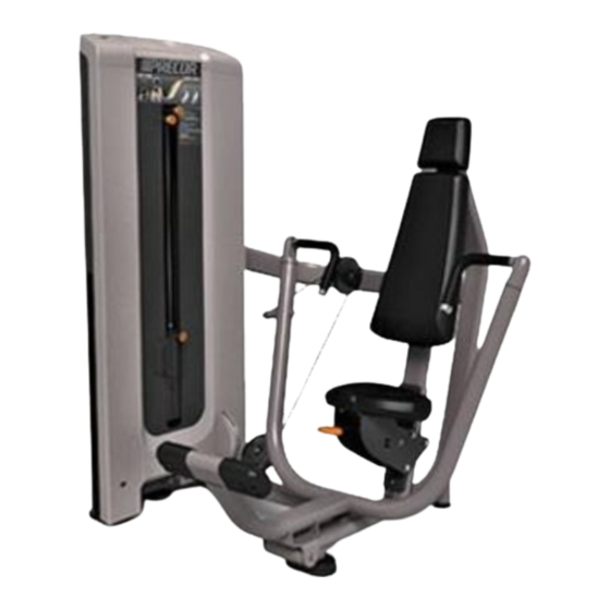
Chest Press
User's Guide
1
3
4
2
Precor Incorporated
20031 142nd Ave NE, P.O. Box 7202, Woodinville, WA USA 98072-4002
1-800-347-4404 • www.precor.com
Important Safety Guidelines
Caution: Before using the equipment, read these instructions and all labels. Failure
to do so may result in serious injury.
• Do not allow children, or those unfamiliar with the operation of this unit, on or
near it.
• Before beginning any fitness program, see your physician for a thorough physical
examination. Ask your physician for the appropriate target heart rate for your
age and fitness level.
• If you feel pain, faintness, or dizziness, stop exercising immediately.
Specifications
Machine Dimensions
Working Area
Weight Stack
Machine Weight
Setup
1. Select an appropriate weight.
2. Adjust the seat so the handles are aligned with your mid-chest.
3. Press the foot assist and grasp both handles.
4. Release the foot assist and place your feet on the floor.
Exercise
• Extend your arms in a slow controlled motion.
• Pause at full extension.
• Slowly return to the start position.
• Use the foot assist to return the handles to the rest position.
Training Tips
• Avoid locking your elbows.
• To vary your routine, use the vertical handles.
58" L x 59" W x 67" H (147 cm W x 150 cm L x 170 cm H)
64" L x 59" W (163 cm L x 150 cm W)
260 lb (118 kg)
615 lb (279 kg)
P/N CW34863-101, en
1 November 2008
©2008 Precor Incorporated
Advertisement
Chapters
Table of Contents

Related Manuals for Precor C404EC


Summary of Contents for Precor C404EC
-
Page 1: Chest Press
Training Tips • Avoid locking your elbows. • To vary your routine, use the vertical handles. P/N CW34863-101, en Precor Incorporated 1 November 2008 20031 142nd Ave NE, P.O. Box 7202, Woodinville, WA USA 98072-4002 ©2008 Precor Incorporated 1-800-347-4404 • www.precor.com... - Page 2 Owner’s Manual Experience Strength™ C-Line...
-
Page 4: Important Safety Guidelines For Owners
Certain Precor commercial strength equipment is Class S/B, C certified bolted to the floor for extra stability. Consult a qualified general contractor according to EN957 –1/2 standards. See an authorized Precor dealer for a for proper fastening methods. complete and current listing of certified machines. -
Page 5: Important Safety Information For Users
Important Safety Information for Users Before beginning any fitness program, you should obtain a complete physical • Do not drop or slam the weight stack while exercising. examination from your physician. • Be sure the selector pin is completely inserted. Use only the pin provided Il est conseillé... -
Page 6: Table Of Contents
Table of Contents Important Safety Guidelines for Owners ........1 Annual Maintenance ..............17 Safety Approval ................1 Weight Stack Annual Maintenance ..........17 Inspect and Lubricate Pop Pins ............ 17 Important Safety Information for Users ......... 2 Commercial Strength Equipment Limited Warranty ..... 18 Before You Begin ................ -
Page 7: Before You Begin
• Complete hex key set from -inch to -inch equipment. If you use parts not approved by Precor, you could void the Precor Limited Warranty. Use of parts not approved by Precor may cause injury. • Rubber mallet Precor recommends that maintenance technicians thoroughly read and understand the safety guidelines and maintenance procedures covered in this manual. -
Page 8: Shroud Removal
Shroud Removal Perform the necessary maintenance. When you are finished, replace the shroud. The Experience Strength product line includes a shroud that must be 1. Attach the Upper Back Shroud first, aligning the tabs at the bottom with removed to perform the maintenance described in this manual. the Lower Back Shroud. -
Page 9: Obtaining Service
If any items are missing, Date purchased: _________________________ contact your dealer. If you need more information regarding customer support numbers or a list of Precor authorized service centers, visit the Precor website at www.precor.com. Model #:... -
Page 10: Daily Inspection
• Inspect pads for wear. pads). • Clean and inspect equipment frames. Important: Do not reupholster pads or use pads not approved by Precor. • Inspect cables and end connections for wear. • Check warning and instructional labels. Clean and Inspect Frames... -
Page 11: Inspect Cables And End Connections
CAUTION: Carefully inspect the cables, pulleys, fasteners, and related hardware regularly. Replace any cable at the first sign of wear using only Precor-supplied replacement parts. With regular use, a cable can become worn and might fail. Sudden failure of a worn cable can cause severe injury to Obtaining Service a user. -
Page 12: Check Warning And Instructional Labels
The following figure shows an example of a user instructional label. Figure 3: Cable bolt must have a minimum of ten threads into the selector stem Check Warning and Instructional Labels Inspect warning and instructional labels daily to make sure that all the information can be clearly read. - Page 13 Precor products come equipped with a number of standard warning labels. Warning The following two figures show sample warning labels you may see on the equipment depending on the model and product line: Improper use of this equipment can result in serious injury.
-
Page 14: Weekly Inspection
Weekly Inspection Clean and Lubricate Cable Rod Ends This section covers the tasks you should perform each week to maintain the equipment. Perform the following tasks as appropriate for the unit you are Check cable rod ends to make sure the shoulder bolts are secure. If cable maintaining: rod ends are noisy, lubricate them with a silicone spray lubricant. -
Page 15: Clean And Lubricate Guide Rods
Clean and Lubricate Guide Rods Inspect Cables, Connections, and Tension Inspect the exposed areas of the guide rods for cleanliness. Using a dry cloth, Each week, give the cables and connections a thorough inspection and check wipe any buildup of dirt or grease from the rods. cable tensions. -
Page 16: Inspect Pulleys
Inspect Pulleys Inspect and Lubricate Bearings and Bushings Precor uses precision ball bearing idler pulleys to guide the cable smoothly. Inspect each pulley for damage, including hairline cracks, chips, or missing Precor uses high quality bearings designed for strength applications and sections. -
Page 17: Check And Lubricate Seat Adjustment
Check and Lubricate Seat Adjustment • Linear Bearings: These bearings allow weight plates and other mechanical parts to travel smoothly along guide rods. (Refer to the The seat adjustment mechanism requires little maintenance. However, following figure.) Inspect the ends of each guide rod to make sure they are because seat safety is important to the safety of a workout, you should check fastened correctly and all bolts are tight. -
Page 18: Monthly Inspection
To remove surface rust from the frame, rub lightly with a fine wet/dry equipment. Perform the following tasks as appropriate for the unit you are sandpaper or fine steel wool. Finish with Precor touch-up paint if needed. maintaining: Maintain paint luster with an application of a mild automotive wax product. -
Page 19: Lubricate Pop Pins
Lubricate Pop Pins Inspect All Fasteners Pull out the pop pin as far as it goes and apply a small amount of silicone Fasteners can loosen with normal use. Inspect all nuts, bolts, screws, and spray lubricant. Wipe off any excess lubricant with a cloth. (Refer to the other fasteners to make sure they are tight and installed correctly. -
Page 20: Annual Maintenance
CAUTION: Pulling out the pop pin may cause the unit to adjust position suddenly. To avoid injury, keep your hands and head away from moving parts. Once a year, Precor recommends disassembling the weight stack to clean Inspect the plunger and spring for excessive wear and damage, and replace and inspect it thoroughly. -
Page 21: Commercial Strength Equipment Limited Warranty
Precor owner’s manual period only. To claim under this warranty, the buyer must notify Precor or your specifications, or failure to provide reasonable and necessary maintenance as authorized Precor dealer within 30 days after the date of discovery of any outlined in the owner’s manual. - Page 22 Exclusive Remedies. For any product described above that fails to conform to its warranty, Precor will provide, at their option, one of the following: (1) repair; (2) replacement; or (3) refund of the purchase price. Precor Limited Warranty service may be obtained by contacting the authorized dealer from whom you purchased the item.
- Page 23 Notes: Experience Strength™ C-Line Owner’s Manual: Notes...
- Page 25 U.S. and foreign patents for both the mechanical construction and the visual aspects P.O. Box 7202 of its product design. Any party contemplating the use of Precor product designs is hereby forewarned Experience Strength™ C-Line Owner’s Manual Woodinville, WA USA 98072-4002...
- Page 26 Assembly and Delivery Guide Experience Strength™ C-Line Chest Press...
- Page 28 Table of Contents Getting Started ..............2 Open the Box ............... 2 Required Tools ..............2 Attach the Feet and Foot Covers ......... 3 Attach the Bottle Holder/Accessory Tray ......6 Assemble the Shroud ............7 Disassemble the Equipment ..........12 Chest Press Assembly and Delivery Guide: Table of Contents...
-
Page 29: Getting Started
One adjustable foot (CW39916-102) Caution: Do not use power tools to tighten screws attaching the weight One foot cover with 90-degree upper opening (front, CW34061-101; stack shroud components. Using power tools may void the Precor back, CW34061-102) warranty. Two #8 x 1 ” Phillips-head self-tapping screws... -
Page 30: Attach The Feet And Foot Covers
Attach the Feet and Foot Covers To Attach the Adjustable Foot: The following graphic shows the location of the adjustable feet. 1. Align the adjustable foot with the hole built into the cylindrical leg. 2. Screw the adjustable foot into the leg until the machine sits level on the floor. - Page 31 Use this illustration to ensure that the foot cover is positioned and To Attach the Foot Covers: attached correctly. Note: When you install each foot cover, no gap should appear between its front and back halves. Also, the opening in the top of the assembled foot cover should align with the angle of the frame leg attached to the foot.
- Page 32 To Adjust the Stability Foot: The stability foot is located centrally underneath the weight stack frame and should rest evenly on the floor. If the foot is not resting firmly on the floor, perform the following procedure. Note: Adjustments to the stability foot must be completed before the shroud is attached.
-
Page 33: Attach The Bottle Holder/Accessory Tray
Attach the Bottle Holder/Accessory Tray 3. Set the bottle holder/accessory tray on top of the bottle holder To Attach the Bottle Holder/Accessory Tray to the bracket and align it with the bracket screw holes. Attach it to the Weight Tower Frame: bracket using: 1. -
Page 34: Assemble The Shroud
Using power tools at the top and facing the weight stack frame. may void the Precor warranty. Screw fasteners into the plastic until the plastic makes full contact with the steel frame. If you overtighten the fasteners, you can damage the plastic shroud cover. - Page 35 To Install the Covers Below the Front Shroud: 3. Slide the bottom edge of the front shroud into the space between the exercise station and the weight stack frame. Note: Do not tighten all fasteners for the bottom covers until all shroud 4.
- Page 36 2. Fasten the cover plate to the second lower corner cover using: 4. Attach the lower middle cover by squeezing and snapping its tabs into the slots in the frame. Two #8 self-tapping screws 5. Firmly press the tabs located at the top of the lower middle cover under the bottom edge of the front shroud.
- Page 37 To Install the Upper and Lower Back Shroud: 1. Position the lower back so that its tabbed end is at the top. Note: Do not tighten any of the screws until all four screws are attached. 2. Line up the two screw holes near the upper corners of the lower back with the corresponding holes in the weight stack frame.
- Page 38 2. Push down on the top cover until its tabs lock into place. Figure 17: Shroud top cover attachment To Remove the Nameplate Protective Film: 1. Locate the Precor nameplates on the front and back sides of the assembled shroud. 2. Peel the protective film off each Precor nameplate.
-
Page 39: Disassemble The Equipment
Disassemble the Equipment This unit arrives fully assembled except for the shrouds and the bottle holder/accessory tray. In some cases, you may need to disassemble the unit before you move it. WARNING: You will need assistance to disassemble this unit. The weight tower is unstable when disconnected from the exercise station. - Page 40 To Separate the Weight Tower from the Exercise 3. Locate the bottom area where the exercise station is bolted to the weight tower. Station: 4. Remove the bolts on the bottom area using a ” hex key and a 1” Note: The exercise station is attached to the weight tower at a side open-end wrench.
- Page 41 To Reroute the Cable During Reassembly: The following illustration shows how the cable is rerouted to the weight stack frame. 1. Check the position of the cable on the movement arm cam and all pulleys to ensure that they are properly seated. Note: Visually check the pulleys to ensure that they are aligned to avoid cable friction and positioned as shown in the illustration.
- Page 42 7. Check the adjustment by inserting the weight pin into every weight WARNING: At the end of the following step, a minimum of 10 threads plate hole. The weight pin should slide easily in and out of each on the cable bolt must be inserted within the weight stack’s selector weight plate.
- Page 43 Notes Chest Press Assembly and Delivery Guide: Notes...
- Page 45 U.S. and foreign patents for both the mechanical construction and the visual aspects P.O. Box 7202 of its product design. Any party contemplating the use of Precor product designs is hereby forewarned Assembly and Delivery Guide CW34833-141 rev D, en Woodinville, WA USA 98072-4002 that Precor considers the unauthorized appropriation of its proprietary rights to be a very serious matter.
Need help?
Do you have a question about the C404EC and is the answer not in the manual?
Questions and answers