Table of Contents
Advertisement
Quick Links
Advertisement
Table of Contents

Related Manuals for Supermicro C2SEA


Summary of Contents for Supermicro C2SEA
- Page 1 C2SEA C2SEE USER’S MANUAL Revision 1.0...
- Page 2 Manual Revision: Rev. 1.0 Release Date: June 18, 2008 Unless you request and receive written permission from Super Micro Computer, Inc., you may not copy any part of this document. Information in this document is subject to change without notice. Other products and companies referred to herein are trademarks or registered trademarks of their respective companies or mark holders.
-
Page 3: Manual Organization
C2SEE motherboard. About this Motherboard The C2SEA/C2SEE supports single Core 2™ Extreme/Core 2™ Quad/Core 2™ Duo Processor with a system bus speed of 1333 MHz/1066 MHz/800 MHz. The Intel Core 2™ Extreme/Core 2™ Quad/Core 2™ Duo Processor supports the 775-Land Grid Array Package that interfaces with the motherboard via an LGA775 socket. -
Page 4: Contacting Supermicro
C2SEA/C2SEE User’s Manual Contacting Supermicro Headquarters Address: Super Micro Computer, Inc. 980 Rock Ave. San Jose, CA 95131 U.S.A. Tel: +1 (408) 503-8000 Fax: +1 (408) 503-8008 Email: marketing@supermicro.com (General Information) support@supermicro.com (Technical Support) Web Site: www.supermicro.com Europe Address: Super Micro Computer B.V. - Page 5 Preface Notes...
-
Page 6: Table Of Contents
1-1 Overview ......................1-1 Checklist ..................... 1-1 C2SEA/C2SEE Image ............... 1-2 C2SEA/C2SEE Layout ............... 1-4 C2SEA/C2SEE Quick Reference ..........1-5 Motherboard Features ................1-6 Intel G45/G43 Express Chipset: System Block Diagram ......1-8 1-2 Chipset Overview ....................1-9 1-3 Recovery from AC Power Loss ............... 1-10 1-4 PC Health Monitoring .................. - Page 7 Table of Contents 2-6 Connecting Cables ..................2-13 ATX/Auxiliary Power Connectors ............2-13 GLAN1 Port ....................2-13 Universal Serial Bus (USB) ..............2-14 GLAN1 Port ....................2-14 Overheat LED/Fan Fail LED ..............2-15 Chassis Intrusion ..................2-15 Fan Headers ..................... 2-16 VGA Connector ..................
- Page 8 C2SEA/C2SEE User’s Manual Chapter 3: Troubleshooting 3-1 Troubleshooting Procedures ................3-1 Before Power On ..................3-1 No Power ....................3-1 No Video ....................3-2 Memory Errors ................... 3-2 Losing the System’s Setup Confi guration ..........3-2 3-2 Technical Support Procedures ................3-3 3-3 Frequently Asked Questions ................
-
Page 9: Chapter 1: Introduction
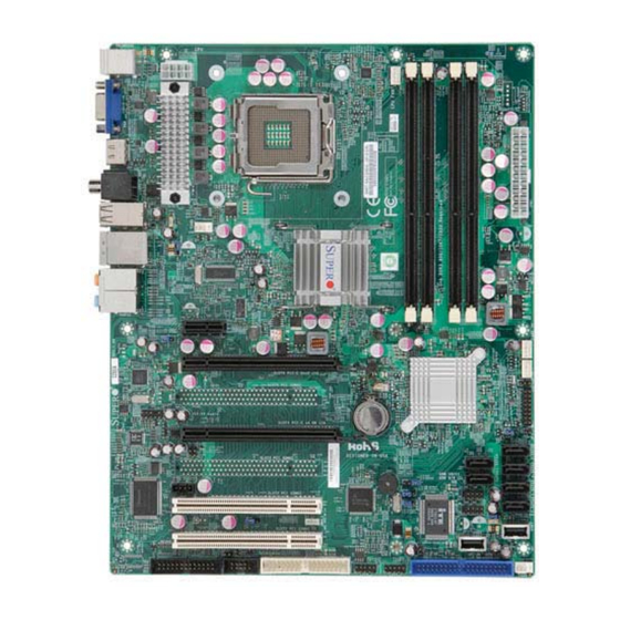
The following items are included in the retail box only: One (1) Supermicro Mainboard Two (2) SATA cables (CBL-0044L) One (1) IDE hard drive cable (CBL-0036L-3) (C2SEA only) One (1) IO Shield (MCP-260-00021-0N) One (1) Supermicro CD containing drivers and utilities... - Page 10 C2SEA/C2SEE User’s Manual C2SEA Motherboard Image Note: All pictures and drawings shown in this manual were based upon the latest PCB Revision available at the time of publishing of the manual. The motherboard you have received may or may not look exactly the same as...
- Page 11 Chapter 1: Introduction Notes...
-
Page 12: C2Sea/C2See Image
• Jumpers not indicated are for testing only. • See Chapter 2 for detailed information on jumpers, I/O ports and JF1 front panel connections. • " " indicates the location of Pin 1. Differences between the C2SEA and C2SEE Models C2SEA C2SEE Chipset... -
Page 13: C2Sea/C2See Quick Reference
PWR Supply System Management Bus (SMB) Header USB 0~1, 2~5 Back Panel Universal Serial Ports USB 6, 8~9, 10~11 Front Panel Accessible USB Headers Video Graphics Connector LED Indicator Description Standby Power LED Indicator Note: IDE, 1394a and HDMI connections are available on C2SEA only. -
Page 14: Motherboard Features
Memory • Up to 8GB of Unbuffered non-ECC DDR3@1066/800 memory for single-channel or dual-channel interleaved mode in four DIMM sockets (C2SEA) • Up to 4GB of Unbuffered non-ECC DDR3@1066/800 memory for single-channel or dual-channel interleaved mode in two DIMM sockets (C2SEE) Chipset •... - Page 15 Realtek RTL8111C Gigabit Ethernet controllers • PS/2 mouse and PS/2 keyboard ports • ITE 8213F Controller supports one IDE channel & two devices (C2SEA only) • 12 USB (Universal Serial Bus) 2.0 ports • Realtek ALC 888 High-Defi nition Audio (HDA) codecs supports 10 DAC Chan- nels •...
-
Page 16: Block Diagram
PCIE_x1 SATAII /300 ICH10 PCI_E x1 Slot SATA x6 PCI_32_BUS USB2.0 ITE 8213F IDE USB x 12 PCI 32 x4 (C2SEE) PCI 32 x2 (C2SEA) W83627DHG TI TSB43AB22A LPC I/O FAN x5 SPI EEPROM Realtek ALC888 Floppy COM1 Parallel C2SEA/C2SEE... -
Page 17: Chipset Overview
Chapter 1: Introduction Chipset Overview The Intel G45/G43 Express Chipset is specially designed for use with Intel Core 2™ Extreme/Core Quad/Core Duo LGA 775 processors. It consists of two primary components: the Graphics and Memory Controller Hub (GMCH), and the I/O Con- troller Hub (ICH10). -
Page 18: Recovery From Ac Power Loss
BIOS chapter of this manual to change this setting. The default set- ting is Power-Off. PC Health Monitoring This section describes the PC health monitoring features of the C2SEA/C2SEE. The motherboard has an onboard System Hardware Monitor chip that supports PC health monitoring. -
Page 19: Power Supply
It is even more important for processors that have high CPU clock rates of 1 GHz and faster. C2SEA/C2SEE accommodates 12V ATX power supplies. Although most power supplies generally meet the specifi cations required by the CPU, some are inadequate. -
Page 20: Versatile Media Capabilities
192 kHz of same rate, and can be used with a variety of microphones for input. In addition to the HD Audio connection, the C2SEA also includes a High-Defi nition Mul- timedia Interface (HDMI) connector on the motherboard. This connector transmits digital signals, providing superb multimedia interface support. -
Page 21: Chapter 2: Installation
Chapter 2: Installation Chapter 2 Installation Static-Sensitive Devices Electrostatic Discharge (ESD) can damage electronic com ponents. To prevent dam- age to your system board, it is important to handle it very carefully. The following measures are generally suffi cient to protect your equipment from ESD. Precautions •... -
Page 22: Processor And Heatsink Installation
C2SEA/C2SEE User's Manual Processor and Heatsink Installation Warning: When handling the processor package, avoid placing direct pressure on the label area of the fan. Notes: 1. Always connect the power cord last and always remove it before add- ing, removing or changing any hardware components. Make sure that you install the processor into the CPU LGA 775 socket before you install the CPU heatsink. - Page 23 Chapter 2: Installation 3. Use your thumb and your index fi n- Top Center Edge ger to hold the CPU at the top center edge and the bottom center edge of the CPU. 4. Align CPU Pin1 (the CPU corner marked with a triangle) against the socket corner that is marked with a Bottom Center Edge...
- Page 24 C2SEA/C2SEE User's Manual Installing the Heatsink 1. Locate the CPU Fan on the mother- board. (Refer to the layout on the right for the CPU Fan location.) 2. Position the heatsink in such a way that the heatsink fan wires are closest to the CPU fan and are not interfered with other components.
- Page 25 Chapter 2: Installation 8. Repeat Step 6 to insert all four heatsink fasteners into the mounting holes. 9. Once all four fasteners are securely insert- ed into the mounting holes and the heatsink is properly installed on the motherboard, con- nect the heatsink fan wires to the CPU Fan connector.
-
Page 26: Installing Dimms
Repeat for all modules (see step 1 above). Memory Support The C2SEA motherboard supports up to 8 GB Unbuffered non-ECC DDR3@1066/800 MHz in 4 DIMMs, and the C2SEE board supports up to 4 GB Unbuffered non-ECC DDR3@1066/800 MHz in 2 DIMMs. -
Page 27: Installing And Removing Dimms
DDR3 Notch Notch Release Note: Notch Release should align C2SEA/C2SEE with the receptive point on the slot To Install: Insert module vertically and press down until it snaps into place. Pay attention to the alignment notch at the bottom. To Remove:... -
Page 28: Control Panel Connectors/Io Ports
Back Panel I/O Port Locations and Defi nitions Back Panel Connectors 1. Keyboard (Purple) 2. PS/2 Mouse (Green) 3. VGA 4. HDMI (C2SEA only) 5. S/PDIF_Out 6. USB Port 2 7. USB Port 3 8. USB Port 4 9. USB Port 5 10. -
Page 29: Front Control Panel
LED indicators. Refer to the following section for descriptions and pin defi nitions. JF1 Header Pins LED_Anode+ Power LED LED_Anode+ HDD LED NIC1 LED LED_Anode+ LED_Anode+ C2SEA/C2SEE OH/Fan Fail LED LED_Anode+ Reset Button Ground Power Button Ground... -
Page 30: Front Control Panel Pin Defi Nitions
C2SEA/C2SEE User's Manual 3. Front Control Panel Pin Defi nitions Power LED Power LED Pin Defi nitions (JF1) The Power LED connection is located Pin# Defi nition on pins 15 and 16 of JF1. Refer to the LED_Anode+ table on the right for pin defi nitions. -
Page 31: Nic1 Led Indicators
Flash- Fan Fail A. NIC1 LED B. OH/Fan Fail LED Fan1 LED_Anode+ Power LED Fan5 HDD LED LED_Anode+ Intel G45 (C2SEA) G43 (C2SEE) NIC1 LED LED_Anode+ Slot7 PCI-E x1 C2SEA/C2SEE JPL1 LED_Anode+ Slot6 PCI-E Gen2 x16 SPI BIOS JBT1 Intel... -
Page 32: Reset Button
C2SEA/C2SEE User's Manual Reset Button Reset Button The Reset Button connection is located Pin Defi nitions (JF1) on pins 3 and 4 of JF1. Attach it to a Pin# Defi nition hardware reset switch on the computer Reset case. Refer to the table on the right for Ground pin defi... -
Page 33: Connecting Cables
1 through 4 Ground 5 through 8 +12V Required Connection A. 24-pin ATX PWR B. 8-pin PWR Fan1 Fan5 Intel G45 (C2SEA) G43 (C2SEE) Slot7 PCI-E x1 C2SEA/C2SEE JPL1 Slot6 PCI-E Gen2 x16 SPI BIOS JBT1 Intel CTRL CMOS CLEAR... -
Page 34: Universal Serial Bus (Usb)
C2SEA/C2SEE User's Manual Universal Serial Bus (USB) Back Panel USB (0~5) There are 12 USB 2.0 (Universal Pin# Defi nitions Serial Bus) ports/headers on the motherboard. Six of them are Back Panel USB ports: USB 0~1 (J4) and USB 2~5 (J7). USB 6, USB 8~9 and... -
Page 35: Overheat Led/Fan Fail Led
Intrusion Input inform you of a chassis intrusion when Ground it is opened. A. Overheat LED B. Chassis Intrusion Fan1 Fan5 Intel G45 (C2SEA) G43 (C2SEE) Slot7 PCI-E x1 C2SEA/C2SEE JPL1 Slot6 PCI-E Gen2 x16 SPI BIOS JBT1 Intel CTRL... -
Page 36: Fan Headers
C2SEA/C2SEE User's Manual Fan Headers The C2SEA/C2SEE has fi ve chassis fan headers (Fan 1 to Fan 5). Fan 1 is the CPU Fan. Fan 2 to Fan 5 are system/ Fan Header chassis fans. Pin Defi nitions (Fan1-3) Note: Pins 1-3 of a 4-pin fan headers Pin# Defi... -
Page 37: Atx Ps/2 Keyboard And Ps/2 Mouse Ports
See the table on the right for pin defi nitions. Ground (NC: No Connection.) A. Keyboard/Mouse B. COM1 Fan1 Fan5 Intel G45 (C2SEA) G43 (C2SEE) Slot7 PCI-E x1 C2SEA/C2SEE JPL1 Slot6 PCI-E Gen2 x16 SPI BIOS JBT1 Intel CTRL... -
Page 38: Wake-On-Ring
C2SEA/C2SEE User's Manual Wake-On-Ring Wake-On-Ring The Wake-On-Ring header is des- Pin Defi nitions ignated JWOR. This function allows (JWOR) your computer to wake-up when Pin# Defi nition receiving an incoming call while in Ground the suspend state. See the table on Wake-up the right for pin defi... -
Page 39: High-Defi Nition Audio (Hda)
Data PWR Fail Ground +3.3V High-Defi nition Audio (HDA) Orange: The C2SEA/C2SEE features a 7.1+2 Channel Blue: Line-In CEN/LFE High-Defi nition Audio (HDA) (J8) codec that Black: Back provides 10 DAC channels, simultaneously Green:Front Surround supporting 7.1 sound playback and two channels... -
Page 40: Front Panel Audio Header
C2SEA/C2SEE User's Manual Front Panel Audio Control FP Audio Pin Defi nitions When front panel headphones are plugged in, Pin# Defi n. the back panel audio output is disabled. This is MIC_L done through the FP Audio header (J12). If the... -
Page 41: S/Pdif_Out Connector
Pin# Defi nition Outside Ground Ground Inside S/PDIF Signal S/PDIF Signal HDMI HDMI Connector (C2SEA only) Pin Defi nitions Pin# Defi n. Pin# Defi n. A High-Definition Multimedia Interface TMDS Data2+ (HDMI) connector is located on the IO Back- TMDS Data2- TMDS Data1+ plane on the motherboard. -
Page 42: 1394_1/1394_2 Connections
C2SEA/C2SEE User's Manual 1394_1/1394_2 Connections (C2SEA 1394_1 Pin Defi nitions only) Pin# Defi n. Pin# Defi n 1394_1 and 1394_2 provide the IEEE PTPA0+ PTPA0- 1394a connections on the motherboard. PTPB0+ PTPB0- See the tables on the right for pin defi -... -
Page 43: Jumper Settings
See the table on the Enabled (default) right for jumper settings. The default set- Disabled ting is enabled. A. GLAN Port 1 Enable Fan1 Fan5 Intel G45 (C2SEA) G43 (C2SEE) Slot7 PCI-E x1 C2SEA/C2SEE JPL1 Slot6 PCI-E Gen2 x16 SPI BIOS JBT1 Intel... -
Page 44: Watch Dog Enable
C2SEA/C2SEE User's Manual Watch Dog Enable/Disable Watch Dog Jumper Settings (JWD) Watch Dog is a system monitor that can re- Jumper Setting Defi nition boot the system when a software application Pins 1-2 Reset hangs. Close pins 1-2 to reset the system if an (default) application hangs. -
Page 45: Pci/Pci-Exp. Slots To Smb Speeds
AC power cord and then close pins 1 and 2 to clear CMOS. A. JI Fan1 B. JI C. JBT1 Fan5 Intel G45 (C2SEA) G43 (C2SEE) Slot7 PCI-E x1 C2SEA/C2SEE JPL1 Slot6 PCI-E Gen2 x16 SPI BIOS JBT1... -
Page 46: Ide Enable/Disable
C2SEA/C2SEE User's Manual IDE Enable/Disable (C2SEA Only) IDE Enable (JPD1) JPD1 enables or disables IDE on the C2SEA. See the table on the right for Pin# Defi nition jumper settings. The default setting Enabled (default) is Enabled. Disabled Audio Enable... -
Page 47: Usb Wake-Up
USB devices from the USB ports whose USB jumpers are set to "Disabled" before the system goes into the standby mode. A. JPUSB1 B. JPUSB2 Fan1 Fan5 Intel G45 (C2SEA) G43 (C2SEE) Slot7 PCI-E x1 C2SEA/C2SEE JPL1 Slot6 PCI-E Gen2 x16 SPI BIOS JBT1... -
Page 48: Onboard Speaker Enable
C2SEA/C2SEE User's Manual Onboard Speaker Enable Onboard Speaker Enable Jumper Settings An onboard speaker (Buzzer) enable Pin Setting Defi nition jumper is located at JD1 on the moth- Pins 3-4 Onboard Speaker erboard. Close pins 3-4 to use the Pins 1-4 External Speaker onboard speaker. -
Page 49: Onboard Indicators
GLAN Activity Indicator LED Setting Color Status Defi nition Green Flashing Active A. GLAN 1 LEDs Fan1 Fan5 Intel G45 (C2SEA) G43 (C2SEE) Slot7 PCI-E x1 C2SEA/C2SEE JPL1 Slot6 PCI-E Gen2 x16 SPI BIOS JBT1 Intel CTRL CMOS CLEAR Slot5 PCI 33MHZ... -
Page 50: Power Led
C2SEA/C2SEE User's Manual Onboard Power LED (LE1) The Onboard 3.3V Standby Power LED is Onboard PWR LED Indicator (LE1) located at LE1 on the motherboard. When LE1 is off, the system is off. When the LED Color Defi nition LED is on, the power is on. Unplug the... -
Page 51: Parallel Port Connector
Data Bit 5 Data Bit 6 Data Bit 7 BUSY Write Data Write Gate SLCT A. Printer Fan1 Fan5 Intel G45 (C2SEA) G43 (C2SEE) Slot7 PCI-E x1 C2SEA/C2SEE JPL1 Slot6 PCI-E Gen2 x16 SPI BIOS JBT1 Intel CTRL CMOS CLEAR... -
Page 52: Ide Connector
Pin Defi nitions There is one IDE Connector on the Pins# Defi nition Pin # Defi nition C2SEA. This connection supports two Reset IDE Ground IDE devices. Be sure to close Pin 1 Host Data 7 Host Data 8 and Pin 2 of JPD1 to enable the IDE... -
Page 53: Chapter 3: Troubleshooting
Chapter 3: Troubleshooting Chapter 3 Troubleshooting Troubleshooting Procedures Use the following procedures to troubleshoot your system. If you have followed all of the procedures below and still need assistance, refer to the ‘Technical Support Procedures’ and/or ‘Returning Merchandise for Service’ section(s) in this chapter. Always disconnect the AC power cord before adding, changing or installing any hardware components. -
Page 54: No Video
C2SEA/C2SEE User's Manual Turn the power switch on and off to test the system. The battery on your motherboard may be old. Check to verify that it still sup- plies ~3VDC. If it does not, replace it with a new one. -
Page 55: Technical Support Procedures
503-8000, option 2, or by fax at (408)503-8019. Frequently Asked Questions Question: What type of memory does my motherboard support? Answer: The C2SEA/C2SEE supports unbuffered, DDR3 1066/800 MHz memory modules. See Section 2-4 for details on installing memory. - Page 56 Question: How do I utilize the onboard HD sound? Answer: The onboard HD sound available on the C2SEA/C2SEE can be enabled with the audio driver software that was included in your motherboard package. When activated, sound will be routed through the jacks next to the LAN Port according to the audio connection descriptions listed on Page 2-8.
-
Page 57: Returning Merchandise For Service
Chapter 3: Troubleshooting drive(s). Consult the documentation that came with your disk drive for details on actual jumper locations and settings. Returning Merchandise for Service A receipt or copy of your invoice marked with the date of purchase is required be- fore any warranty service will be rendered. - Page 58 C2SEA/C2SEE User's Manual Notes...
-
Page 59: Chapter 4: Bios
BIOS Introduction This chapter describes the AMI BIOS Setup Utility for the C2SEA/C2SEE. The AMI ROM BIOS is stored in a Flash EEPROM and can be easily updated. This chapter describes the basic navigation of the AMI BIOS Setup Utility setup screens. - Page 60 C2SEA/C2SEE User’s Manual screens. An AMI BIOS identifi cation string is displayed at the left bottom corner of the screen, below the copyright message. Warning!! Do not shut down or reset the system while updating BIOS to prevent possible boot failure.
- Page 61 Chapter 4: AMI BIOS Processor When you select this option, the AMI BIOS will automatically display the status of processors as shown below: Speed Count Core System Memory This option allows the AMI BIOS to display the status of memory modules installed in the system.
-
Page 62: Advanced Setup
C2SEA/C2SEE User’s Manual Advanced Setup Confi gurations Use the arrow keys to select Boot Setup and hit <Enter> to access the submenu items: BIOS Features QuickBoot If Enabled, this option will skip certain tests during POST to reduce the time needed for system boot. - Page 63 Chapter 4: AMI BIOS ACPI Confi guration Use this feature to confi gure ACPI (Advanced Confi guration and Power Interface) power management settings for your system. ACPI Aware OS Select Yes to enable ACPI support for the OS. Disable this feature if ACPI is not supported by your OS.
- Page 64 C2SEA/C2SEE User’s Manual 19 at boot and allow the drives that are attached to these host adaptors to func- tion as bootable disks. If this item is set to Disabled, the ROM BIOS of the host adaptors will not capture Interrupt 19, and the drives attached to these adaptors will not function as bootable devices.
- Page 65 Chapter 4: AMI BIOS off and restart the system for the change to take effect. Please refer to Intel’s web site for detailed information. Execute Disable Bit (Available when supported by the OS and the CPU) Set to Enabled to enable the Execute Disable Bit to allow the processor to classify areas in the system memory where an application code can execute and where it cannot, thus preventing a worm or a virus from creating a fl...
-
Page 66: Advanced Chipset Settings
C2SEA/C2SEE User’s Manual Advanced Chipset Settings The items included in the Advanced Settings submenu are listed below: NorthBridge Confi guration This feature allows the user to confi gure the settings for the Intel 945GME NorthBridge chipset. Memory Remap Feature PCI memory resources will overlap with the total physical memory if 4GB of memory or above is installed on the motherboard. - Page 67 Chapter 4: AMI BIOS IGD GTT Graphics Memory Size This feature allows the user to select the IGD GTT Graphics Size. The Default setting is No VT Mode, 2 MB. PAVP Mode Use the feature to select the Protect Audio Video Path Mode. The options are Disabled, Lite, and Paranoid.
- Page 68 C2SEA/C2SEE User’s Manual TV Standard This feature allows the user to determine how TV-Standard is handled by the system. The options are VBIOS-Default, NTSC, PAL, SECAM, SMPTE 240M, ITU-R-Television, SMPTE 295M, SMPTE 296M, EIA-770.2, and EIA-770.3. Spread Spectrum Mode If Enabled, the BIOS will monitor the level of Electromagnetic Interference caused by the components and will attempt to decrease the interference when- ever needed.
- Page 69 Chapter 4: AMI BIOS USB Confi guration This feature allows the user to confi gure USB settings for the motherboard. USB Devices Enabled This item displays the USB devices that are detected by the BIOS. Legacy USB Support Select Enabled to use Legacy USB devices. If this item is set to Auto, Legacy USB support will be automatically enabled if a legacy USB device is installed on the motherboard, and vise versa.
- Page 70 C2SEA/C2SEE User’s Manual Confi gure SATA#1 As This feature allows the user to select the drive type for SATA#1. The options are IDE and AHCI. Primary IDE Channels Master/Slave, Secondary IDE Channels Maser/Slave and Third IDE Channels Maser/Slave These settings allow the user to set the parameters of Primary IDE Master/Slave, Secondary IDE Master/Slave and Third IDE Master/Slave slots.
- Page 71 Chapter 4: AMI BIOS DMA Mode Select Auto to allow the BIOS to automatically detect IDE DMA mode when the IDE disk drive support cannot be determined. Select SWDMA0 to allow the BIOS to use Single Word DMA mode 0. It has a data transfer rate of 2.1 MBs. Select SWDMA1 to allow the BIOS to use Single Word DMA mode 1.
- Page 72 C2SEA/C2SEE User’s Manual PCI/PnP Confi guration This feature allows the user to set the PCI/PnP confi gurations for the following items: Clear NVRAM Select Yes to clear NVRAM during system boot. The options are Yes and No. Plug & Play OS Select Yes to allow the OS to confi...
- Page 73 Chapter 4: AMI BIOS Super IO Confi guration Serial Port1 Address This option specifi es the base I/O port address and the Interrupt Request address of Serial Port 1. Select Disabled to prevent the serial port from accessing any system resources.
- Page 74 C2SEA/C2SEE User’s Manual Hardware Health Confi guration This feature allows the user to monitor Hardware Health of the system and review the status of each item when displayed. System Temperature, CPU Temperature Fan Speed Control Modes This feature allows the user to decide how the system controls the speeds of the onboard fans.
-
Page 75: Security Setup
Chapter 4: AMI BIOS Security Settings The AMI BIOS provides a Supervisor and a User password. If you use both pass- words, the Supervisor password must be set fi rst. Supervisor Password Is: This item indicates if a supervisor password has been entered for the system. Clear means such a password has not been used and Set means a supervisor password has been entered for the system. -
Page 76: Boot Settings
C2SEA/C2SEE User’s Manual Boot Confi guration Use this feature to confi gure Boot Settings: Boot Device Priority This feature allows the user to specify the sequence of priority for the Boot De- vice. The settings are 1st Floppy Drive and Disabled. The default settings are the fol- lowing: •... -
Page 77: Exit
Chapter 4: AMI BIOS Exit Options Select the Exit tab from the AMI BIOS Setup Utility screen to enter the Exit BIOS Setup screen. Save Changes and Exit When you have completed the system confi guration changes, select this option to leave the BIOS Setup Utility and reboot the computer, so the new system con- fi... - Page 78 C2SEA/C2SEE User’s Manual Load Fail-Safe Defaults To set this feature, select Load Fail-Safe Defaults from the Exit menu and press <Enter>. The Fail-Safe settings are designed for maximum system stability, but not for maximum performance. 4-20...
-
Page 79: Bios Error Beep Codes
Appendix A: AMIBIOS Error Beep Codes Appendix A BIOS Error Beep Codes During the POST (Power-On Self-Test) routines, which are performed each time the system is powered on, errors may occur. Non-fatal errors are those which, in most cases, allow the system to continue the boot-up process. - Page 80 C2SEA/C2SEE User’s Manual Notes...
- Page 81 Appendix B: BIOS POST Checkpoint Codes Appendix B BIOS POST Checkpoint Codes When the AMIBIOS performs the Power On Self Test, it writes checkpoint codes to I/O port 0080h. If the computer cannot complete the boot process, diagnostic equipment can be attached to the computer to read I/O port 0080h. Uncompressed Initialization Codes The uncompressed initialization checkpoint codes are listed in order of execution: Checkpoint...
- Page 82 C2SEA/C2SEE User's Manual Bootblock Recovery Codes The bootblock recovery checkpoint codes are listed in order of execution: Checkpoint Code Description The onboard fl oppy controller if available is initialized. Next, beginning the base 512 KB memory test. Initializing the interrupt vector table next.
- Page 83 Appendix B: BIOS POST Checkpoint Codes Uncompressed Initialization Codes The following runtime checkpoint codes are listed in order of execution. These codes are uncompressed in F0000h shadow RAM. Checkpoint Code Description The NMI is disabled. Next, checking for a soft reset or a power on condition. The BIOS stack has been built.
- Page 84 C2SEA/C2SEE User's Manual Checkpoint Code Description Interrupt vector initialization is done. Clearing the password if the POST DIAG switch is on. Any initialization before setting video mode will be done next. Initialization before setting the video mode is complete. Confi guring the mono- chrome mode and color mode settings next.
- Page 85 Appendix B: BIOS POST Checkpoint Codes Checkpoint Code Description The memory below 1 MB has been cleared via a soft reset. Clearing the memory above 1 MB next. The memory above 1 MB has been cleared via a soft reset. Saving the memory size next.
- Page 86 C2SEA/C2SEE User's Manual Checkpoint Code Description The password was checked. Performing any required programming before WIN- BIOS Setup next. The programming before WINBIOS Setup has completed. Uncompressing the WINBIOS Setup code and executing the AMIBIOS Setup or WINBIOS Setup utility next.
- Page 87 Appendix B: BIOS POST Checkpoint Codes Checkpoint Code Description Returned from adaptor ROM at E000h control. Performing any initialization required after the E000 option ROM had control next. Initialization after E000 option ROM control has completed. Displaying the system confi guration next. Uncompressing the DMI data and executing DMI POST initialization next.
- Page 88 C2SEA/C2SEE User's Manual Notes...
-
Page 89: Software Installation Instructions
Appendix C: Software Installation Instructions Appendix C Software Installation Instructions C-1 Installing Drivers After you've installed the Windows Operating System, a screen as shown below will appear. You are ready to install software programs and drivers that have not yet been installed. To install these software programs and drivers, click the icons to the right of these items. - Page 90 C2SEA/C2SEE User's Manual C-2 Confi guring Supero Doctor III The Supero Doctor III program is a Web-base management tool that supports remote management capability. It includes Remote and Local Management tools. The local management is called the SD III Client. The Supero Doctor III program included on the CDROM that came with your motherboard allows you to monitor the environment and operations of your system.
- Page 91 Appendix C: Software Installation Instructions Supero Doctor III Interface Display Screen-II (Remote Control) Note: SD III Software Revision 1.0 can be downloaded from our Web site at: ftp://ftp.supermicro.com/utility/Supero_Doctor_III/. You can also download SDIII User's Guide at: http://www.supermicro.com/PRODUCT/ Manuals/SDIII/UserGuide.pdf. For Linux, we will still recommend that you use Supero Doctor II.
- Page 92 C2SEA/C2SEE User's Manual Notes...
Need help?
Do you have a question about the C2SEA and is the answer not in the manual?
Questions and answers