
Related Manuals for Avalue Technology ECM-CFS


Summary of Contents for Avalue Technology ECM-CFS
- Page 1 ECM-CFS 3.5" Coffee Lake-S Micro Module User’s Manual Ed – 14 November 2019 Copyright Notice Copyright 2019 Avalue Technology Inc., ALL RIGHTS RESERVED. Part No. E2047394204R...
- Page 2 These answers are normally a lot more detailed than the ones we can give over the phone. So please consult the user’s manual first. To receive the latest version of the user’s manual; please visit our Web site at: http://www.avalue.com.tw/ 2 ECM-CFS User’s Manual...
-
Page 3: Table Of Contents
Signal Description – Audio connector (JAUDIO1) ................25 2.3.18.1 2.3.19 EC Debug connector (JEC_ROM1)..................26 2.3.20 PC Buzzer header (JBZ1) ..................... 26 Audio/USB Daughter Board User’s Guide ............27 2.4.1 Jumper and Connector Layout....................... 27 2.4.2 Jumper and Connector List ......................27 ECM-CFS User’s Manual... - Page 4 3.6.3.2 PCH-IO Configuration ........................50 3.6.3.2.1 PCI Express Configuration ....................... 51 3.6.3.2.1.1 Intel I211 LAN Chip (PCI-E Port 6) ..................51 3.6.3.2.1.2 mPCIe/mSATA Slot (PEI-E Port 15) ..................52 3.6.3.2.2 SATA And RST Configuration ......................53 4 ECM-CFS User’s Manual...
- Page 5 Install Display Driver .................... 65 Install LAN Driver ....................66 Install ME Driver ....................68 Install Serial IO Driver ..................69 Install Audio Driver (For Realtek ALC892) ............70 Install IRST Driver ....................71 5. Mechanical Drawing ....................73 ECM-CFS User’s Manual...
-
Page 6: Getting Started
1.2 Packing List Before you begin installing your single board, please make sure that the following materials have been shipped: 1 x ECM-CFS 3.5” Micro Module 1 x AUX-032 daughter board ... -
Page 7: Document Amendment History
Revision Date Comment August 2018 Avalue Initial Release July 2019 Avalue Update 2.3 Setting Jumpers & Connectors August 2019 Avalue Update 1.5 System Specifications October 2019 Avalue Remove CEC1 connector November 2019 Avalue Update 1.5 System Specifications ECM-CFS User’s Manual... -
Page 8: Manual Objectives
We strongly recommend that you study this manual carefully before attempting to set up ECM-CFS or change the standard configurations. Whilst all the necessary information is available in this manual we would recommend that unless you are confident, you contact your supplier for guidance. -
Page 9: System Specifications
2 x HDMI: 4096 x 2304@30Hz (cost reduce) Q370 support Triple Display H310 only support Dual Display:LVDS+HDMI1(default LVDS enable)or Multiple Display HDMI1+HDMI2(LVDS disabled) HDMI HDMI 1.4 LCD Interface Dual channel 18/24-bit LVDS (via 7511B) Audio AC97 Codec Realtek ALC892 HD codec Supports 5.1-CH Audio ECM-CFS User’s Manual... - Page 10 Operating Humidity 0% ~ 90% relative humidity, non-condensing Size (L x W) 5.7" x 4" (146mm x 101mm) Weight 0.44 lbs (0.2 Kg) OS Support Win 10 / Linux Note: Specifications are subject to change without notice. 10 ECM-CFS User’s Manual...
-
Page 11: Architecture Overview-Block Diagram
User’s Manual 1.6 Architecture Overview—Block Diagram The following block diagram shows the architecture and main components of ECM-CFS. ECM-CFS User’s Manual 11... -
Page 12: Hardware Configuration
ECM-CFS User’s Manual 2. Hardware Configuration Note: If you need more information, please visit our website: http://www.avalue.com.tw 12 ECM-CFS User’s Manual... -
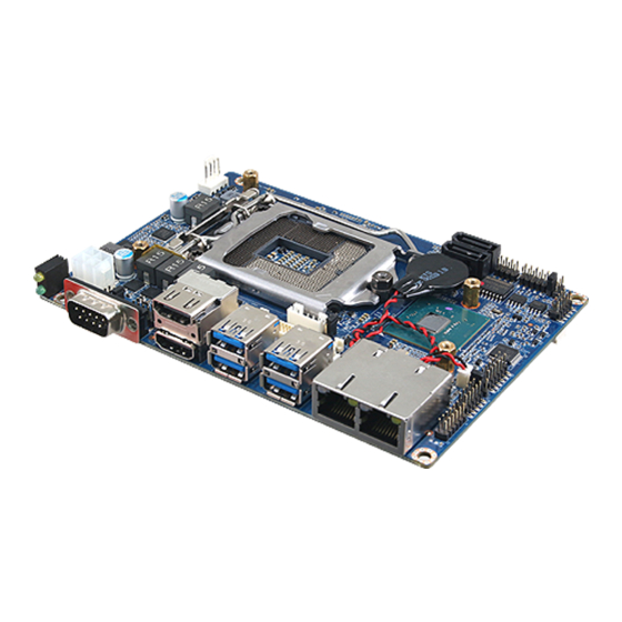
Page 13: Product Overviews
User’s Manual 2.1 Product Overviews ECM-CFS User’s Manual 13... - Page 14 ECM-CFS User’s Manual 14 ECM-CFS User’s Manual...
-
Page 15: Jumper & Connector List
2 x 2 wafer, pitch 4.20 mm SATA_PWR1 SATA power connector 1 2 x 1 wafer, pitch 2.00 mm SATA_PWR2 SATA power connector 2 2 x 1 wafer, pitch 2.00 mm SATA1/2 Serial ATA connector 1/2 ECM-CFS User’s Manual 15... - Page 16 ECM-CFS User’s Manual JBZ1 PC Buzzer header 2 x 1 wafer, pitch 2.00 mm JEC_ROM1 EC Debug connector 3 x 1 header, pitch 2.00 mm MINI_PCIE1 Full size Mini-PCI-e connector DDR4 SODIMM socket SO_DIMM1 16 ECM-CFS User’s Manual...
-
Page 17: Setting Jumpers & Connectors
User’s Manual 2.3 Setting Jumpers & Connectors 2.3.1 Clear CMOS (JBAT1) Protect* Clear CMOS * Default 2.3.2 Serial port 1 pin9 signal select (JRI1) Ring* +12V * Default ECM-CFS User’s Manual 17... -
Page 18: At/Atx Input Power Select (Jat1)
ECM-CFS User’s Manual 2.3.3 AT/ATX Input power select (JAT1) 2.3.4 LCD backlight brightness adjustment (JBKL_SEL1) PWM Mode* DC Mode * Default 18 ECM-CFS User’s Manual... -
Page 19: Lcd Inverter Connector (Jbkl1)
User’s Manual 2.3.5 LCD Inverter connector (JBKL1) Signal +12V BKLEN VBRIGHT 2.3.6 CPU fan connector (CPU_FAN1) Signal +12V CFAN_IN CFAN_OUT ECM-CFS User’s Manual 19... -
Page 20: Serial Port 2 Connector (Jcom1)
Serial port 2 connector (JCOM1) Signal PIN PIN Signal COM_RI#_2 COM_CTS#_2 COM_RTS#_2 COM_DSR#_2 COM_DTR#_2 COM_TXD_2 COM_RXD_2 COM_DCD#_2 2.3.8 General purpose I/O connector (JDIO1) Signal PIN PIN Signal DIO_GP20 DIO_GP10 DIO_GP21 DIO_GP11 DIO_GP22 DIO_GP12 DIO_GP23 DIO_GP13 SMB_SCL_S0 SMB_SDA_S0 20 ECM-CFS User’s Manual... -
Page 21: Sata Power Connector 1 (Sata_Pwr1)
User’s Manual 2.3.9 SATA power connector 1 (SATA_PWR1) Signal SATA_PWR1 2.3.10 SATA power connector 2 (SATA_PWR2) Signal SATA_PWR2 ECM-CFS User’s Manual 21... -
Page 22: Power Connector (Pwr1)
ECM-CFS User’s Manual 2.3.11 Power connector (PWR1) Signal PIN PIN Signal +12V +12V 2.3.12 On-board header for USB2.0 (JUSB1) Signal PIN PIN Signal +5VSB USB_R_DN5 USB_R_DP5 USB_R_DP6 USB_R_DN6 +5VSB 22 ECM-CFS User’s Manual... -
Page 23: Lpc Connector (Jlpc1)
LPC_AD2 LPC_LFRAME# LPC_AD3 CLK1_LPC_DEBUG LPC_SERIRQ 2.3.14 LVDS connector (JLVDS1) Signal PIN PIN Signal +3.3V +3.3V LVDS_DATA0_P LVDS_DATA1_P LVDS_DATA0_N LVDS_DATA1_N LVDS_DATA2_P LVDS_DATA3_P LVDS_DATA2_N LVDS_DATA3_N LVDS_DATA4_P LVDS_DATA5_P LVDS_DATA4_N LVDS_DATA5_N LVDS_DATA6_P LVDS_DATA7_P LVDS_DATA6_N LVDS_DATA7_N LVDS_CLK1_P LVDS_CLK2_P LVDS_CLK1_N LVDS_CLK2_N +12V ECM-CFS User’s Manual 23... -
Page 24: Front Panel Connector (Jfp1)
ECM-CFS User’s Manual 2.3.15 Front Panel connector (JFP1) Signal Signal PWRBTN_IN# PM_SYSRST# FP_PWR_LED+ PWR_LED# HDD_LED# CASE_OPEN# 2.3.16 SPI connector (JSPI1) Signal PIN PIN Signal +3.3VSB SPI_CS0# SPI_CLK SPI_MISO SPI_MOSI BIOS_HOLD# BIOS_WP# 24 ECM-CFS User’s Manual... -
Page 25: Battery Connector (Bat1)
HD_AGND HD_AGND LINE1-R-IN LIN1-L-IN MIC1-R-IN MIC1-L-IN FRONT-JD LINE1-JD MIC1-JD HD_AGND 2.3.18.1 Signal Description – Audio connector (JAUDIO1) Signal Signal Description LINE1-JD AUDIO IN (LINE_RIN/LIN)sense pin FRONT-JD AUDIO Out(ROUT/LOUT) sense pin MIC1-JD MIC IN (MIC_RIN/LIN) sense pin ECM-CFS User’s Manual 25... -
Page 26: Ec Debug Connector (Jec_Rom1)
ECM-CFS User’s Manual 2.3.19 EC Debug connector (JEC_ROM1) Signal EC_SMCLK_DBG EC_SMDAT_DBG 2.3.20 PC Buzzer header (JBZ1) Signal SPKR 26 ECM-CFS User’s Manual... -
Page 27: Audio/Usb Daughter Board User's Guide
2.54mm USB connector 5 x 2 header, pitch 2.54mm 5 x 2 header, pitch 2.0mm 2.0mm USB connector 5 x 2 header, pitch 2.0mm 2.0mm USB connector TV / Audio connector 8 x 2 header, pitch 2.54mm ECM-CFS User’s Manual 27... -
Page 28: Setting Jumper And Connector
Mic Bais Line out L Line out R SPK L SPK R Line in L Line in R TVGND TVGND COMP 2.0mm USB Connector (JP4) 2.0mm USB Connector (JP5) Signal PIN PIN Signal Signal PIN PIN Signal 28 ECM-CFS User’s Manual... -
Page 29: Bios Setup
User’s Manual 3.BIOS Setup ECM-CFS User’s Manual 29... -
Page 30: Introduction
If the message disappears before you respond and you still wish to enter Setup, restart the system to try again by turning it OFF then ON or pressing the "RESET" button on the system case. You may also restart by simultaneously pressing <Ctrl>, <Alt>, and <Delete> keys. 30 ECM-CFS User’s Manual... -
Page 31: Using Setup
Note: Some of the navigation keys differ from one screen to another. To Display a Sub Menu Use the arrow keys to move the cursor to the sub menu you want. Then press <Enter>. A “” pointer marks all sub menus. ECM-CFS User’s Manual 31... -
Page 32: Getting Help
Even a seemingly small change to the chipset setup has the potential for causing you to use the override. 32 ECM-CFS User’s Manual... -
Page 33: Bios Setup
<Enter> to accept and enter the sub-menu. 3.6.1 Main Menu This section allows you to record some basic hardware configurations in your computer and set the system clock. ECM-CFS User’s Manual 33... -
Page 34: System Language
Visit the Avalue website (www.avalue.com.tw) to download the latest product and BIOS information. 3.6.2 Advanced Menu This section allows you to configure your CPU and other system devices for basic operation through the following sub-menus. 34 ECM-CFS User’s Manual... -
Page 35: Cpu Configuration
Item Options Description When enabled, a VMM can utilize the additional Intel (VMX) Virtualization Disabled hardware capabilities provided by Vanderpool Technology Enabled[Default] Technology. All[Default] Number of cores to enable in each processor Active Processor Cores package. ECM-CFS User’s Manual 35... -
Page 36: Cpu - Power Management Control
Disabled[Default], Package C-State Enabled Package C-State Un-demotion. Un-demotion Disabled[Default], C0/C1 Maximum Package C State Limit Setting. CPU Default: Leaves to Factory default value. Auto: Package C State Limit Initializes to deepest available Package C State Limit. 36 ECM-CFS User’s Manual... -
Page 37: Pch-Fw Configuration
Disabled Mode. When disable AMT BIOS Features are no longer Disabled, supported and user is no longer able to access AMT BIOS Features Enabled[Default] MEBx Setup. Note: This option does not disable Manageability Features in FW. ECM-CFS User’s Manual 37... -
Page 38: Oem Flags Settings
OEMFlag Bit 15: Unconfigure ME with resetting Unconfigure ME Enabled MEBx password to default. 3.6.2.2.2 Firmware Update Configuration Item Option Description Disabled[Default], OEMFlag Bit 15: Unconfigure ME with resetting Unconfigure ME Enabled MEBx password to default. 38 ECM-CFS User’s Manual... -
Page 39: Trusted Computing
3.6.2.3 Trusted Computing Item Options Description Enables or Disables BIOS support for security device. Disable, Security Device Support O.S. will not show Security Device. TCG EFI protocol Enable[Default] and INT1A interface will not be available. 3.6.2.4 APCI Settings ECM-CFS User’s Manual 39... -
Page 40: It8528 Super Io Configuration
You can use this item to set up or change the IT8528 Super IO configuration for serial ports. Please refer to 3.6.2.5.1~ 3.6.2.5.2 for more information. Item Description Serial Port 1 Configuration Set Parameters of Serial Port 1 (COMA). Serial Port 2 Configuration Set Parameters of Serial Port 2 (COMB). 40 ECM-CFS User’s Manual... -
Page 41: Serial Port 1 Configuration
3.6.2.5.1 Serial Port 1 Configuration Item Option Description Enabled[Default], Serial Port Enable or Disable Serial Port (COM). Disabled 3.6.2.5.2 Serial Port 2 Configuration Item Option Description Enabled[Default], Serial Port Enable or Disable Serial Port (COM). Disabled ECM-CFS User’s Manual 41... -
Page 42: Ec 8528 Hw Monitor
ECM-CFS User’s Manual 3.6.2.6 EC 8528 HW Monitor Item Options Description Enabled, Smart Fan Function Enables or Disables Smart Fan. Disabled[Default] 3.6.2.7 S5 RTC Wake Settings 42 ECM-CFS User’s Manual... -
Page 43: Serial Port Console Redirection
Wake system from S5 Fixed Time Select Dynamic Time, System will wake on the current time Dynamic Time + Increase minute(s). 3.6.2.8 Serial Port Console Redirection Item Options Description Disabled[Default], Console Redirection Console Redirection Enable or Disable. Enabled ECM-CFS User’s Manual 43... -
Page 44: Legacy Console Redirection Settings
Console Redirection is disabled before booting to Always legacy OS. When Always Enable is selected, Redirect After POST Enable[Default] then Legacy Console Redirection is enabled for BootLoader legacy OS. Default setting for this option is set to Always Enable. 44 ECM-CFS User’s Manual... -
Page 45: Usb Configuration
Mass storage device emulation type. ‘AUTO’ Auto[Default] Floppy enumerates devices according to their media Mass Storage Devices Forced FDD format. Optical drives are emulated as ‘CDROM’, drives with no media will be Hard Disk CD-ROM emulated according to a drive type. ECM-CFS User’s Manual 45... -
Page 46: Network Stack Configuration
ECM-CFS User’s Manual 3.6.2.10 Network Stack Configuration Item Options Description Enabled Network Stack Enable/Disable UEFI Network Stack. Disabled[Default] 3.6.2.11 NVMe Configuration 46 ECM-CFS User’s Manual... -
Page 47: Chipset
User’s Manual 3.6.3 Chipset 3.6.3.1 System Agent (SA) Configuration Item Option Description Enabled[Default] VT-d VT-d capability. Disabled ECM-CFS User’s Manual 47... -
Page 48: Memory Configuration
1.25 GB 1.5 GB Maximum Value of TOLUD. Dynamic assignment 1.75 GB Max TOLUD would adjust TOLUD automatically based on largest 2 GB MMIO length of installed graphic controller. 2.25 GB 2.5 GB 2.75 GB 3 GB 48 ECM-CFS User’s Manual... -
Page 49: Graphics Configuration
User’s Manual 3.6.3.1.2 Graphics Configuration Item Option Description Select which of IGFX/PEG/PCI Graphics device Auto[Default] Primary Display should be Primary Display Or select SG for IGFX Switchable Gfx. GTT Size Select the GTT Size. 8MB[Default] ECM-CFS User’s Manual 49... -
Page 50: Dmi/Opi Configuration
ECM-CFS User’s Manual 3.6.3.1.3 DMI/OPI Configuration 3.6.3.2 PCH-IO Configuration Item Option Description Disabled PCH LAN Controller Enable/Disable onboard NIC. Enabled[Default] 50 ECM-CFS User’s Manual... -
Page 51: Pci Express Configuration
Description Enabled[Default], Intel I211 LAN Chip (PCI-E Port 6) Control the PCI Express Root Port. Disabled Set the ASPM Level: Force L0s – Force all Disabled, ASPM 5 links to L0s State AUTO – BIOS auto ECM-CFS User’s Manual 51... -
Page 52: Mpcie/Msata Slot (Pei-E Port 15)
L0s State AUTO – BIOS auto ASPM 14 configure DISABLE – Disables ASPM. L0sL1 Auto[Default] Disabled, L1 Substates L1.1 PCI Express L1 Substates settings. L1.1 & L1.2[Default] Auto[Default] PCIe Speed Gen1 Configure PCIe Speed. Gen2 52 ECM-CFS User’s Manual... -
Page 53: Sata And Rst Configuration
The Mode Enable/Disable (Loop Back). Disabled[Default] Enabled[Default] SATA Port Enable or Disable SATA Port. Disabled Hard Disk Drive[Default] Identify the SATA port is connected to Solid SATA Device Type Solid State Drive State Drive or Hard Disk Drive. ECM-CFS User’s Manual 53... -
Page 54: Hd Audio Configuration
3.6.3.2.3 HD Audio Configuration Item Option Description Control Detection of the HD-Audio device. Disable = HDA Disabled HD Audio will be unconditionally disabled Enabled = HDA will be Enabled[Default] unconditionally enabled 3.6.3.3 Board & Panel Configuration 54 ECM-CFS User’s Manual... - Page 55 50 sec Watch Dog Select WatchDog. 1 min 2 min 10 min 30 min Disabled Wake Up by Ring Wake Up by Ring from S3/S4/S5. Enabled[Default] Disabled Enable/Disabled USB Standby Power USB Standby Power Enabled[Default] during S3/S4/S5. ECM-CFS User’s Manual 55...
-
Page 56: Security
ECM-CFS User’s Manual 3.6.4 Security Administrator Password Set setup Administrator Password User Password Set User Password 3.6.4.1 Secure Boot 56 ECM-CFS User’s Manual... -
Page 57: Key Management
Enabled System is in User mode. The mode chagne requires platform reset. Secure Boot mode selector: Standard/Custom. In Standard Secure Boot Mode Custom mode Secure Boot Variables can be Custom[Default] configured without authentication. 3.6.4.1.1 Key Management ECM-CFS User’s Manual 57... - Page 58 ECM-CFS User’s Manual 58 ECM-CFS User’s Manual...
- Page 59 User’s Manual ECM-CFS User’s Manual 59...
- Page 60 ECM-CFS User’s Manual 60 ECM-CFS User’s Manual...
-
Page 61: Boot
Setup Prompt Timeout 1~ 65535 key. 65535(0xFFFF) means indefinite waiting. Bootup NumLock State Select the Keyboard NumLock state Off[Default] Disabled[Default] Quiet Boot Enables or disables Quiet Boot option Enabled Boot Option #1 Set the system boot order. ECM-CFS User’s Manual 61... -
Page 62: Save And Exit
This option restores all BIOS settings to the factory default. This option is useful if the controller exhibits unpredictable behavior due to an incorrect or inappropriate BIOS setting. 3.6.6.4 Launch EFI Shell from filesystem device Attempts to Launch EFI Shell application (Shellx64.efi) from one of the available filesystem devices. 62 ECM-CFS User’s Manual... -
Page 63: Drivers Installation
User’s Manual 4. Drivers Installation Note: Installation procedures and screen shots in this section are for your reference and may not be exactly the same as shown on your screen. ECM-CFS User’s Manual 63... -
Page 64: Install Chipset Driver
Windows 10 operation system. If the warning message appears while the installation process, click Continue to go on. Step 3. Click Install. Step1. Click Next. Step 4. Complete setup. Step 2. Click Accept. 64 ECM-CFS User’s Manual... -
Page 65: Install Display Driver
Windows 10 operation system. Step 3. Click Next. Step 4. Click Next. Step 1. Click Next to continue installation. Step 2. Click Yes to accept license Step 5. Click Finish to complete setup. agreement. ECM-CFS User’s Manual 65... -
Page 66: Install Lan Driver
Note: The installation procedures and screen shots in this section are based on Windows 10 operation system. Step 3. Click Next. Step 1. Click Install Drivers and Software. Step 4. Click Next. Step 2. Click Next. Step 5. Click Install. 66 ECM-CFS User’s Manual... - Page 67 User’s Manual Step 6. Click Finish to complete setup. ECM-CFS User’s Manual 67...
-
Page 68: Install Me Driver
If the warning message appears while the installation process, click Continue to go on. Step 3. Click Next. Step1. Click Next to start installation. Step 4. Click Finish to complete setup. Step 2. Click Next. 68 ECM-CFS User’s Manual... -
Page 69: Install Serial Io Driver
Note: The installation procedures and screen shots in this section are based on Windows 10 operation system. Step 3. Click Next. Step 1. Click Next to continue installation. Step 4. Click Next. Step 2. Click Next. Step 5. Complete setup. ECM-CFS User’s Manual 69... -
Page 70: Install Audio Driver (For Realtek Alc892)
All drivers can be found on the Avalue Official Website: http://www.avalue.com.tw. Note: The installation procedures and screen shots in this section are based on Windows 10 operation system. Step 1. Click Next to continue installation. Step 2. Click Finish to complete setup. 70 ECM-CFS User’s Manual... -
Page 71: Install Irst Driver
Note: The installation procedures and screen shots in this section are based on Windows 10 operation system. Step 3. Click Next. Step 1. Click Next to continue installation. Step 4. Click Next. Step 2. Click Next. Step 5. Complete setup. ECM-CFS User’s Manual 71... - Page 72 ECM-CFS User’s Manual Step 6. Click Finish to complete setup. 72 ECM-CFS User’s Manual...
-
Page 73: Mechanical Drawing
User’s Manual 5. Mechanical Drawing ECM-CFS User’s Manual 73... - Page 74 ECM-CFS User’s Manual Unit: mm 74 ECM-CFS User’s Manual...
- Page 75 User’s Manual Unit: mm ECM-CFS User’s Manual 75...
Need help?
Do you have a question about the ECM-CFS and is the answer not in the manual?
Questions and answers