
Subscribe to Our Youtube Channel
Related Manuals for Black Box LB510A-R2


Summary of Contents for Black Box LB510A-R2
- Page 1 LB510A-R2 10BASE-T/100BASE-TX G.SHDSL Two-Wire Extender/NTU Extend corporate LAN-to-WAN communications at higher speeds or at a longer distance.
-
Page 2: Table Of Contents
Black Box G.SHDSL.bis EFM CPE TABLE OF CONTENTS GENERAL INFORMATION .................9 Features ....................9 Description..................9 Power Input Connector ..............10 1.3.1 External AC universal power supply ........10 1.3.2 External 48 VDC power supply ..........11 CONFIGURATION..................11 Software (CLI) Configuration ............11 Hardware (dip-switch) Configuration .......... - Page 3 Table of Contents Establishing a Remote Console Session .......... 29 5.1.1 How to Connect ..............29 5.1.2 How to Disconnect..............31 5.1.3 Differences in local and remote control session behavior ..31 SOFTWARE UPGRADE ................32 RESET CONFIGURATION TO FACTORY DEFAULTS ......33 SPECIFICATIONS ..................
- Page 4 Black Box G.SHDSL.bis EFM CPE C.1 Line Port ...................39 C.1.1 RJ-45..................39 C.2 ETHERNET PORT ................39 C.2.1 RJ-45 socket 10/100Base-T.............39 Page 4 724-746-5500 | blackbox.com...
- Page 5 RADIO FREQUENCY INTERFERENCE STATEMENTS RADIO FREQUENCY INTERFERENCE STATEMENTS FEDERAL COMMUNICATIONS COMMISSION AND INDUSTRY CANADA RADIO FREQUENCY INTERFERENCE STATEMENTS This equipment generates, uses, and can radiate radio-frequency energy, and if not installed and used properly, that is, in strict accordance with the manufacturer’s instructions, may cause interference to radio communication.
- Page 6 Black Box G.SHDSL.bis EFM CPE INSTRUCCIONES DE SEGURIDAD (Normas Oficiales Mexicanas Electrical Safety Statement) 4. Todas las instrucciones de seguridad y operación deberán ser leídas antes de que el aparato eléctrico sea operado. 5. Las instrucciones de seguridad y operación deberán ser guardadas para referen- cia futura.
-
Page 7: Instrucciones De Seguridad
INSTRUCCIONES DE SEGURIDAD 17.El equipo eléctrico debe ser limpiado únicamente de acuerdo a las recomenda- ciones del fabricante. 18.En caso de existir, una antena externa deberá ser localizada lejos de las lineas de energia. 19.El cable de corriente deberá ser desconectado del cuando el equipo no sea usado por un largo periodo de tiempo. - Page 8 Black Box G.SHDSL.bis EFM CPE SAFETY WHEN WORKING WITH ELECTRICITY • This device contains no user serviceable parts. This device can only be repaired by qualified service personnel. • Do not open the device when the power cord is connected.
- Page 9 In accordance with the requirements of council directive 2002/96/EC on Waste of Electrical and Electronic Equipment (WEEE), ensure that at end-of-life you separate this product from other waste and scrap and deliver to the WEEE col- lection system in your country for recycling. This device contains no user serviceable parts.
-
Page 10: General Information
Black Box G.SHDSL.bis EFM CPE 1. GENERAL INFORMATION Thank you for your purchase of this Black Box product. This product has been thor- oughly inspected and tested and is warranted for one year for parts and labor. If any questions or problems arise during installation or use of this product, contact Black Box Technical Support at 724-746-5500 or info@blackbox.com. -
Page 11: Power Input Connector
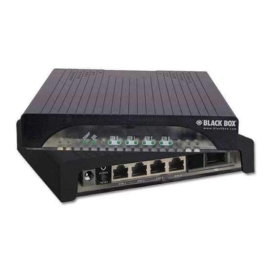
LB510A-R2 Figure 1. 1.3 POWER INPUT CONNECTOR The LB510A-R2 comes with an AC or DC power supply. (See Appendix A.7 on page 36.) The power connection to the CPE is a 2.5 mm barrel receptacle with the center con- ductor positive (see figure 2). -
Page 12: External 48 Vdc Power Supply
To use DIP-switch configuration you must first set the DIP switches to a position other than all OFF or all ON before powering-up the LB510A-R2. When all the DIP switches are set to any position other than all OFF or all ON, the LB510A-R2 will operate in Page 12... -
Page 13: Hardware (Dip-Switch) Configuration
(DIP-switch)-configuration mode. In DIP-switch-configuration mode the device will read the DIP-switch settings during system startup and configure itself according to the switch settings. Once you power-up the LB510A-R2 in DIP-switch mode, it will operate in DIP-switch mode until powered down. When operating in DIP- switch mode you cannot change any configuration settings: •... -
Page 14: Configuring The Dip Switches
This section describes switch locations and discusses the configuration options available. NOTE: By default, the LB510A-R2’s DIP switches are all set to “OFF” so the CPE can be configured via G.SHDSL.bis EFM DSLAM. If that is how you will be configuring the CPE, skip ahead to section “Ethernet Management Port”... -
Page 15: System Reset Mode
If the DIP switches are set to anything other than all OFF or all ON, the LB510A-R2 will operate in DIP switch configuration mode. Once the device is powered up and operating in DIP switch configuration mode, you cannot change configuration by any method until you power it down again. -
Page 16: Switches S4-2 Through S4-8 Define The Dsl Line Rate
ON - Annex B S1-6 Annex OFF - Annex A S1-7 Reserved Reserved ON - CO S1-8 DSL Mode OFF - CPE LB510A-R2 S3 DIP-Switch functions (test modes and patterns) Table 3: Position Function S3-1 S3-2 Reserved S3-3 S3-4 S3-5 511e Pattern... - Page 17 S4-2 S4-3 S4-4 S4-5 S4-6 S4-7 S4-8 Data Rate (kbps) 1024 1088 1152 1216 1280 1344 1408 1472 1536 1600 1664 1728 1792 1856 1920 1984 2048 2112 2176 2240 2304 2368 2432 2496 2560 2624 2688 2752 Page 17 724-746-5500 | blackbox.com...
- Page 18 Black Box G.SHDSL.bis EFM CPE S4-2 S4-3 S4-4 S4-5 S4-6 S4-7 S4-8 Data Rate (kbps) 2816 2880 2944 3008 3072 3136 3200 3264 3328 3392 3456 3520 3584 3648 3712 3776 3840 3904 3968 4032 4096 4160 4224 4288 4352...
-
Page 19: Ethernet Management Port
5696 2.6 ETHERNET MANAGEMENT PORT The LB510A-R2 offers a 10/100 Ethernet port for configuration and management via Telnet sessions. Because the Ethernet port is configured as MDI, a crossover Ethernet cable is required when connecting directly from a local PC or laptop. The Ethernet interface default IP address is 192.168.200.1. -
Page 20: Help Commands
Black Box G.SHDSL.bis EFM CPE • DSL Sync State: Out of Sync, Acquiring Sync, In Sync, or Losing Sync. NOTE: DSL Link State vs. DSL Sync State—The DSL link state describes whether the DSL is training (in progress), linked (success), deactivated (we don’t have an option to deactivate the modem, so the user should not see this), or idle. -
Page 21: System Configuration Commands
• dsl show errcntr help: Lists all the commands that start with dsl show errcntr that the console recognizes. 2.6.2 System Configuration Commands The following commands allow the user to configure the system: • system set password <password>: Sets the system password (1-10 charac- ters). -
Page 22: Dsl Status Command
The dsl clear errcntrs command clears the error counters. 2.7 REMOTE CONSOLE Provided that there is a DSL link to a second LB510A-R2, a user may login to the first LB510A-R2’s console and enter the remote console command to access the second LB301A-R2’s console. -
Page 23: Safety When Working With Electricity
0 tx: port 0 rx: port 1 tx: port 1 rx: port 2 tx: port 2 rx: port 3 tx: port 3 rx: LB510A-R2> system show config configuration mode: software logout timer: clocking dsl timeslots: system circuit id: Black Box LB510A-R2... -
Page 24: Installation
Black Box G.SHDSL.bis EFM CPE 3. INSTALLATION Once the LB510A-R2 is properly configured, it is ready to connect to the DSL interface and to the power source. This section explains how to make these connections. LB510A-R2 (DSL, Multi-Port Ethernet) Reset... -
Page 25: Connecting The Ethernet Interface
CAUTION ground. 2. Connect the barrel plug to the Power connector on the LB510A-R2. NOTE: The LB510A-R2 powers up as soon as it is plugged into an AC outlet—there is no power switch. Page 25 724-746-5500 | blackbox.com... -
Page 26: Dc Power
Black Box G.SHDSL.bis EFM CPE 3.3.2 DC Power The 36-60 VDC DC to DC adapter is supplied with the DC version of the LB510A-R2. The black and red leads plug into a DC source (nominal 48VDC) and the barrel power connector plugs into the barrel power supply jack on the LB510A-R2. -
Page 27: Power (Green)
Ethernet Port Activity & Link DSL Link Power LB510A-R2 front panel Figure 6. 4.2.1 Power (Green) The Power LED glows solid during normal operation. At startup, during the POST, the LED blinks once every second. If the POST fails, the unit does not enter normal opera- tion, and the LED blinks once every 0.4 seconds. -
Page 28: Test Modes
The LB510A-R2 offers test modes in the form of loopbacks, prbs pattern generators, and combinations of both. This section discusses how the test modes work. Figure 6 is a block diagram of the LB510A-R2 with respect to test modes. LB510A-R2 block diagram Figure 7. -
Page 29: Patterns
The PC user (near-end) may configure and verify status of the remote LB510A-R2 (far- end) via a Remote Console session. The PC user must log onto the LB510A-R2 (near- end) unit to establish a remote console session. Once done, the remote LB510A-R2 (far-end) appears as a unit which is locally connected through the console port. -
Page 30: Establishing A Remote Console Session
4. At the command prompt, enter the command remote console. 5. Wait for the message Console: Remote console connection established. -If a DSL link is not established, or for some other reason the LB510A-R2 (far- end) does not respond in a reasonable amount of time, the following message appears: Console: Remote console timed out trying to connect. - Page 31 NOTE: The local or remote LB510A-R2 may be CO or CPE, as long as there is one of each. Either the CO or CPE unit may accept a remote console connection.
-
Page 32: How To Disconnect
The timeout period is a fixed, non-configurable parameter of 5 minutes. If the remote LB510A-R2 (far-end) has received no command within 5 minutes, it automatically ter- minates the RCS. Once the RCS is terminated, the PC (far-end) can establish a local console session if desired. -
Page 33: Software Upgrade
The software upgrade feature is available through BOOTP/TFTP. The software upgrade takes approximately 2-3 minutes to complete. To upgrade the software: 1. Connect to the LB510A-R2 via the Ethernet management port and a Telnet ses- sion. 2. Enter the system show info command to view the unit’s MAC address. -
Page 34: Reset Configuration To Factory Defaults
The configuration can be reset to factory defaults using DIP switch S1. A factory reset allows a user to recover from a forgotten password. To reset to the configuration: 1. Turn the LB510A-R2 off. 2. Turn the S1-1 switch to the ON position. -
Page 35: Specifications
Reset configuration to factory defaults A. SPECIFICATIONS A.1 CLOCKING MODES Internal, external or receive recovered A.2 DTE RATE All 64k steps from 64 to 5696 kbps A.3 ETHERNET INTERFACE • Four RJ-45 • 10/100base-t • IEEE802.3 Ethernet A.4 DIAGNOSTICS V.52 compliant (511) pattern generator and detector with error injection mode con- trolled by front-panel switch. -
Page 36: Configuration
A.6 CONFIGURATION Configuration is done with either externally accessible DIP switches, CLI or through the EOC (Embedded Operations Channel) from a LB510A-R2 G.SHDSL DSLAM. A.7 POWER AND POWER SUPPLY SPECIFICATIONS The CPE comes with either an AC or DC power supply;... -
Page 37: External 48 Vdc Power Supply
Reset configuration to factory defaults A.7.2 E 48 VDC XTERNAL POWER SUPPLY The external DC adaptor shall be a listed limited power source that incorporates a disconnect device and shall be positioned within easy reach of the operator. The interconnecting cables shall be rated for the proper voltage, current, anticipated temperature, WARNING flammability, and mechanical serviceability. -
Page 38: Temperature Range
6.22 W x 1.25 H x 4.75 D in. (157 W x 318 H x 120 D mm) A.17 THIRD PARTY SOFTWARE LICENSES NOTE: the LB510A-R2 includes software developed under third party licenses. contact black box for more information. B. FACTORY DEFAULT VALUES B.1 FACTORY DEFAULT VALUES FOR SOFTWARE-CONFIGURABLE... -
Page 39: Factory Default Values For Software-Configuration Parameters
Reset configuration to factory defaults C. INTERFACE PINOUTS C.1 LINE PORT C.1.1 RJ-45 • Pin 4: Tip • Pin 5: Ring • Pins 1, 2, 3, 6, 7, 8: no connection C.2 ETHERNET PORT C.2.1 RJ-45 10/100B SOCKET • Pin 1: TX+ •... - Page 40 Reset configuration to factory defaults 724-746-5500 | blackbox.com...
Need help?
Do you have a question about the LB510A-R2 and is the answer not in the manual?
Questions and answers