
Subscribe to Our Youtube Channel
Related Manuals for Black Box LB522A-KIT


Summary of Contents for Black Box LB522A-KIT
- Page 1 LB522A-KIT LB524A-KIT LB528A-KIT DeeSL.2 Ethernet Extender Extend corporate LAN communications at higher speeds or at a longer distance.
-
Page 2: Table Of Contents
Black Box DeeSL.2 Ethernet Extender TABLE OF CONTENTS GENERAL INFORMATION ...............10 Features ....................10 Description..................10 LB52xA-KIT front Panel ..............11 1.3.1 LED Descriptions ..............11 LB52xA-KIT Rear Panel ..............12 1.4.1 Port Descriptions ..............12 Reset Button ..................13 Ground Terminal................14 Applications Overview ................ - Page 3 Table of Contents 4.3.3 Configuring 802.1Q VLAN Tagging ........39 4.3.4 Quality of Service (QoS)............41 4.3.5 Rate Limit ................54 4.3.6 Flow Control ................. 55 Status Options .................. 55 4.4.1 LINE Status ................55 4.4.2 Management Status ............. 56 4.4.3 LAN Status ................
- Page 4 Black Box DeeSL.2 Ethernet Extender 5.11 Write Command................96 5.12 Reboot Command................97 5.13 Ping Command ................. 97 5.14 Administration Command Menu ............98 5.14.1 User Profile .................98 5.14.2 Security ................100 5.14.3 SNMP ................101 5.14.4 Supervisor Password and ID ..........103 5.15 Utility Command Menu ..............
- Page 5 RADIO FREQUENCY INTERFERENCE STATEMENTS RADIO FREQUENCY INTERFERENCE STATEMENTS FEDERAL COMMUNICATIONS COMMISSION AND INDUSTRY CANADA RADIO FREQUENCY INTERFERENCE STATEMENTS This equipment generates, uses, and can radiate radio-frequency energy, and if not installed and used properly, that is, in strict accordance with the manufacturer’s instructions, may cause interference to radio communication.
- Page 6 Black Box DeeSL.2 Ethernet Extender INSTRUCCIONES DE SEGURIDAD (Normas Oficiales Mexicanas Electrical Safety Statement) 1. Todas las instrucciones de seguridad y operación deberán ser leídas antes de que el aparato eléctrico sea operado. 2. Las instrucciones de seguridad y operación deberán ser guardadas para referen- cia futura.
-
Page 7: Instrucciones De Seguridad
INSTRUCCIONES DE SEGURIDAD 14.El equipo eléctrico debe ser limpiado únicamente de acuerdo a las recomenda- ciones del fabricante. 15.En caso de existir, una antena externa deberá ser localizada lejos de las lineas de energia. 16.El cable de corriente deberá ser desconectado del cuando el equipo no sea usado por un largo periodo de tiempo. - Page 8 Black Box DeeSL.2 Ethernet Extender SAFETY WHEN WORKING WITH ELECTRICITY • This device contains no user serviceable parts. This device can only be repaired by qualified service personnel. • Do not open the device when the power cord is connected.
- Page 9 In accordance with the requirements of council directive 2002/96/EC on Waste of Electrical and Electronic Equipment (WEEE), ensure that at end-of-life you separate this product from other waste and scrap and deliver to the WEEE col- lection system in your country for recycling. This device contains no user serviceable parts.
-
Page 10: General Information
ROI and initial investment perspective over fiber roll-outs. Black Box’s LB52xA-KIT Ethernet Extender incorporates multi-pair bonding to offer an unmatched rate, reach and reliable Ethernet connectivity, providing symmetrical 22.8 Mbps of bandwidth over 4-pair (8-wire) at distances up to 1.8 miles (2.9 km). -
Page 11: Lb52Xa-Kit Front Panel
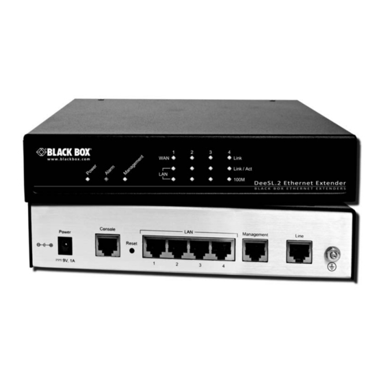
Refer to Appendix A for a complete feature description of the LB52xA-KIT. LB52xA-KIT Figure 1. 1.3 LB52XA-KIT FRONT PANEL 1.3.1 LED Descriptions The front panel LEDs display the status of the power, system, Ethernet ports, and Line port. Figure 2. shows the front panel LED indicators and Table 1 provides a description of the LED indicators’... -
Page 12: Lb52Xa-Kit Rear Panel
LAN (1-4) 100M LAN port is on 10M mode 1.4 LB52XA-KIT REAR PANEL 1.4.1 Port Descriptions The Black Box LB52xA-KIT rear panel ports are shown in the figure below and described in Table 2. n s o 9 V , 1... -
Page 13: Reset Button
Power LED starts blinking. The unit will restart with factory default configuration. • To restart the unit in bootloader mode (to be used only by trained Black Box tech- nicians)—Start with the unit powered off. Press and hold the Reset button while applying power to the unit. -
Page 14: Ground Terminal
ROI and initial investment perspective over fiber roll-outs. 2.1 TYPICAL APPLICATION The Black Box Extenders are the perfect fit for simple, cost-effective high speed Ether- net Extension. They allow customers to take advantage of the existing copper infra- structure to connect remote LANs across distances and at speeds previously unthought-of. - Page 15 Applications Overview LB52xA-KIT application Figure 4. Page 15 724-746-5500 | blackbox.com...
-
Page 16: Distance Charts
Black Box DeeSL.2 Ethernet Extender 2.2 DISTANCE CHARTS 2.2.1 Distance Chart LB52xA-KIT Series - Auto Mode (TCPAM-32/16) Distance Chart LB52xA-KIT Table 3: Line Rate Distance Line 522A 524A 528A 26 AWG/ 24 AWG/ 22 AWG/ Speed 2-Wire 4-Wire 8-Wire 0.4mm 0.5mm... -
Page 17: Distance Chart Lb52Xa-Kit Series - Tcpam-128
Line Rate Distance Line 522A 524A 528A 26 AWG/ 24 AWG/ 22 AWG/ Speed 2-Wire 4-Wire 8-Wire 0.4mm 0.5mm 0.65mm kbps kbps kbps 1408 2816 5632 14.0 15.5 21.0 1728 3456 6912 13.0 14.5 20.0 2176 4352 8704 12.0 14.5 18.5 2496 4995... -
Page 18: Hardware Installation
Black Box DeeSL.2 Ethernet Extender Line Rate Distance Line 522A 524A 528A 26 AWG/ 24 AWG/ 22 AWG/ Speed 2-Wire 4-Wire 8-Wire 0.4mm 0.5mm 0.65mm kbps kbps kbps 2496 4992 9984 11.0 13.0 17.0 2880 5760 11520 10.0 12.0 15.5... -
Page 19: Network Diagram
Hardware Installation When you finish preparing for your installation, go to section “Installing the LB52xA- KIT” on page 20 to install the device. 3.1.1 Network Diagram Draw a network overview diagram that displays all neighboring IP nodes, connected elements and telephony components. Figure 5. shows possible network connections to the LB52xA-KIT. -
Page 20: Ac Power Mains
Black Box DeeSL.2 Ethernet Extender 3.1.3 AC Power Mains If you suspect that your AC power is not reliable, for example if room lights flicker often or there is machinery with large motors nearby, have a qualified professional test the power. -
Page 21: Connecting Cables
Hardware Installation NOTE: Power cables are shipped separately from the LB52xA-KIT 3.1.6 Connecting cables The Interconnecting cables must be acceptable for external use and must be rated for the proper application with respect to volt- age, current, anticipated temperature, flammability, and mechani- CAUTION cal serviceability. - Page 22 Black Box DeeSL.2 Ethernet Extender Grounding stud Figure 6. 2. Install the grounding wire between the grounding stud (see Figure 6.) and the grounding source. 3. Connect the power adapter to the DC 9V port on the LB52xA-KIT, and then con- nect to the power source.
-
Page 23: Configuring The Lb52Xa-Kit
Hardware Installation 3.2 CONFIGURING THE LB52XA-KIT There are three different ways you can configure the LB52xA-KIT—the serial console, Telnet or a web browser. 3.2.1 Web configuration requirements Make sure that the PC you use for configuration has an Ethernet adapter and TCP/IP installed. -
Page 24: Web Configuration
Black Box DeeSL.2 Ethernet Extender login, use admin for both fields. All display screens are the same as the serial console configuration. The default IP address is 192.168.1.1, but you may change the IP address for your application. NOTE: For detailed information on configuring the LB52xA-KIT through Telnet, see Section 5., “Console and Telnet Configuration”... -
Page 25: System Login
Web Configuration 4. Click on the IP address tab and select Obtain IP address automatically. Click 4.1.2 System Login You may use a web browser such as Internet Explorer on your PC to connect the LB52xA-KIT. Type “http://” and the IP address, such as “http://192.168.1.1”. The default IP address and sub net-mask of the Management port of the LB52xA-KIT are 192.168.1.1 and 255.255.255.0. -
Page 26: Basic Configuration Options
Black Box DeeSL.2 Ethernet Extender 4.2 BASIC CONFIGURATION OPTIONS This section contains information for setting up the Operation mode and Management port IP, DHCP server, and LAN via the WMI. Figure 8. shows a flowchart demonstrat- ing basic setup via the WMI for the LB52xA-KIT. - Page 27 Web Configuration 1. From the main menu, click Basic to display the basic installation page. Operation mode and Management port setup page Figure 9. 2. For Operation mode, select the radio button for CPE (Customer Premises Equip- ment) or CO (Central Office). When using a “LAN to LAN” connection, one side must be set as CO and the other side must be set as CPE.
-
Page 28: Dhcp Server
Black Box DeeSL.2 Ethernet Extender 4.2.2 DHCP server Dynamic Host Configuration Protocol (DHCP) is a communication protocol that allows network administrators to manage and automate the assignment of Internet Protocol (IP) addresses in an organization's network. Each machine that can connect to the Internet requires a unique IP address. -
Page 29: Lan
Web Configuration 5. Click Next to commit your changes and continue to the LAN page (refer to the next section). Basic DHCP setup Figure 10. 4.2.3 LAN To configure LAN settings through the WMI: 1. Click on Basic from the main menu. Set up the Operation Mode and Manage- ment port, then click Next. - Page 30 Black Box DeeSL.2 Ethernet Extender LAN setup page Figure 11. 2. Choose an option for the LAN Type. If you select Disable or Dynamic IP, click Next at the bottom of the screen to save your changes. If you select Static IP, you can enter information for IP, Subnet Mask, Gateway and DNS Server's IP.
-
Page 31: Review And Save Basic Setup Changes
Web Configuration 4.2.4 Review and save basic setup changes 1. Once you have entered information on the pages for Operation Mode and Man- agement Port, DHCP Server, and LAN, the Basic Setup Review page will dis- play to confirm your changes. Review and save basic setup changes Figure 12. - Page 32 Black Box DeeSL.2 Ethernet Extender Main Rate, SNR Margin, and Line Probe settings for LINE parameters (refer to the fol- lowing sections to explore each of the configuration options). LINE page Figure 13. Link Select the line type for your model from the Link drop-down list. Line type means how many wires you want to use on the line side.
- Page 33 Main Rate Chart Table 7: TCPAM - 16 TCPAM - 32 TCPAM - Model Type Multiple = 3-60 = 12-89 128 = 2-239 LB522A-KIT 2-wire 192-3840 768-5696 128-15296 LB524A-KIT 4-wire 384-7680 1536-11392 256-30592 LB528A-KIT 8-wire 768-15360 3072-22784...
-
Page 34: Vlan
Black Box DeeSL.2 Ethernet Extender 4.3.2 VLAN Click on VLAN under Advanced on the main menu to reach the VLAN advanced con- figuration page. VLAN page Figure 14. VLAN (Virtual Local Area Network) allows a physical network to be partitioned into multiple logical networks. - Page 35 Web Configuration VID 20 W AN5 W AN4 VID 10 VID 30 W AN3 W AN6 W AN2 W AN7 W AN1 W AN8 Backbone Long Range Ethernet Extender LAN2 LAN1 LAN3 LAN4 VID 30 VID 20 VID 10 VLAN Diagram Figure 15.
- Page 36 Black Box DeeSL.2 Ethernet Extender 802.1Q Tag-Based VLAN Click on VLAN under Advanced on the main menu to reach the VLAN advanced con- figuration page. Then, select the radio button for 802.1Q Tag-Based VLAN to display the configuration options. 802.1Q Tag-Based VLAN page Figure 16.
- Page 37 Web Configuration An Ethernet packet that contains a VLAN ID is called a tagged packet. An Ethernet packet without a VLAN ID is called an untagged packet. Typically, all packets leave untagged, unless tagged by the adapter prior to arriving at the switch port. Egress and Ingress Rules.
- Page 38 Black Box DeeSL.2 Ethernet Extender The Tag Control Information (TCI) section of a VLAN tag includes information on the user Priority level, the Canonical Format Indicator (CFI) and VLAN ID (VID). • Tag Protocol Identifier (TPID) is a defined value of 8100 in hex. When a frame has the EtherType equal to 8100, this frame carries the tag IEEE 802.1Q /...
-
Page 39: Configuring 802.1Q Vlan Tagging
Web Configuration SERVER 802.1Q VLAN LAN1 LAN1 LAN2 LAN2 STU-C STU-R Extender connection LAN3 LAN3 SERVER LAN4 LAN4 VOIP VOIP 802.1Q VLAN diagram Figure 18. Configuring 802.1Q VLAN Tagging. Before enabling VLANs for the LB52xA-KIT, you must first assign each port to the VLAN group(s) in which it will participate. By default all ports are assigned to VLAN1 as untagged ports. - Page 40 Black Box DeeSL.2 Ethernet Extender • Port Overlapping - You can use port overlapping to allow access to commonly shared network resources among different VLAN groups, such as file servers or printers. • Untagged VLANs - Untagged (or static) VLANs are typically used to reduce broadcast traffic and to increase security.
-
Page 41: Quality Of Service (Qos)
Web Configuration Port-Based VLANs are VLANs where the packet forwarding decision is based on the destination MAC address and its associated port. When using port-based VLAN, the port is assigned to a specific VLAN independent of the user or system attached to the port. - Page 42 Black Box DeeSL.2 Ethernet Extender Port Based Priority Click on QoS under Advanced on the main menu to reach the QoS advanced config- uration page. Then, select the radio button for Port Based Priority to display the con- figuration options.
- Page 43 Web Configuration If you select Type 2 or Type 3, refer to “WFQ Configuration” on page 43. The Queue types are Weight Round Robin (WRR), Weighted Fair Queuing (WFQ), Best Effort (BE) and Strictly Priority (SP). Refer to the following page for more infor- mation on how each Queue Type operates.
- Page 44 Black Box DeeSL.2 Ethernet Extender • Best Effort (BE): The BE Queue Type is used for data applications that have low priority or the potential to delay. BE does not use traffic priority or weight assignments, therefore BE is not recommended for high priority data, such as video or voice.
- Page 45 Web Configuration WRR Configuration. If you selected Type 1 in the Scheduling Configuration section, then provide information for the WRR table. Assign a weight value (from 1 to 15) to determine the priority for each queue. QoS - Port Based Priority - WRR Configuration Figure 26.
- Page 46 Black Box DeeSL.2 Ethernet Extender VLAN Tag Priority Click on QoS under Advanced on the main menu to reach the QoS advanced config- uration page. Then, select the radio button for VLAN Tag Priority to display the config- uration options.
- Page 47 Web Configuration VLAN Tag Priority uses the tag field information that has been inserted into an Ether- net frame. If a port has an 802.1Q-compliant device attached (such as this Ethernet Extender), these tagged frames can carry VLAN membership information. IEEE 802.1Q Tagged Frame for Ethernet Figure 30.
- Page 48 Black Box DeeSL.2 Ethernet Extender WRR Configuration. If you selected Type 1 in the Scheduling Configuration sec- tion, then provide information for the WRR table. Assign a weight value (from 1 to 15) to determine the priority for each queue. “Weight” determines how important the queue is;...
- Page 49 Web Configuration Configuration Example. As an example, you can set the LB52xA-KIT to use Weighted Round-Robin (WRR) queuing that specifies a relative weight of each queue. WRR uses a predefined relative weight for each queue that determines the percentage of service time to provide each queue before moving on to the next queue. This pre- vents the head-of-line blocking that can occur with strict priority queuing.
- Page 50 Black Box DeeSL.2 Ethernet Extender - Queue 1 Packets will go first because weight is equal to 15 (the biggest value). - Queue 3 Packets will go next because the weight is the second largest value. - Queue 2 Packets are the next after Queue 3 Packets.
- Page 51 Web Configuration Click on QoS under Advanced on the main menu to reach the QoS advanced config- uration page. Then, select the radio button for IP DSCP Priority to display the configu- ration options. QoS advanced configuration Figure 36. Scheduling Configuration. The LB52xA-KIT provides three combinations of four commonly used techniques: Type 1, Type 2 and Type 3.
- Page 52 Black Box DeeSL.2 Ethernet Extender WFQ Configuration. If you selected Type 2 or Type 3 in the Scheduling Configura- tion section, then provide information for the WFQ table. Assign the bandwidth for each queue in each port. QoS - IP DSCP Priority - WFQ Configuration Figure 38.
- Page 53 Web Configuration IP DSCP Configuration Example. In this example, the selected operation is Type 3. For the Type 3 combination, et up Queue 1 and Queue 2 for WFQ configuration. For this example, assume the following actions: • Assign DSCP 1 to Queue 0. •...
-
Page 54: Rate Limit
Black Box DeeSL.2 Ethernet Extender 4.3.4 Rate Limit Click on Rate Limit under Advanced on the main menu to reach the Rate Control configuration page. Rate Limit page Figure 41. Limiting bandwidth to specific users and ports helps control network congestion, ensure high performance, create efficient networks, and prevent a small number of users from monopolizing network bandwidth. -
Page 55: Flow Control
Web Configuration 4.3.5 Flow Control Click on Flow Control under Advanced on the main menu to reach the Flow Control configuration page. When the Flow Control option is enabled, the LB52xA-KIT controls the packet size. Flow Control page Figure 42. 4.4 STATUS OPTIONS This section contains information for monitoring status options for the LB52xA-KIT via the WMI. -
Page 56: Management Status
Black Box DeeSL.2 Ethernet Extender If two LB52xA-KITs have been linked together, you can view their run-time line rate status and performance information from this screen. If you want to clear the perfor- mance data, click Clear CRC Error. NOTE: The CPE line rate is determined by the CO setting. -
Page 57: Performance Status
Web Configuration 4.4.4 Performance Status The Performance Status page displays information about the uptime and errors of the system. Performance Status page Figure 46. Page 57 724-746-5500 | blackbox.com... -
Page 58: Administration Options
Black Box DeeSL.2 Ethernet Extender 4.5 ADMINISTRATION OPTIONS This section allows you to configure administration options for Security, Simple Net- work Management Protocol (SNMP) and Remote System Log. 4.5.1 Security Administration For system security, you should change the default user name and password during initial setup. -
Page 59: Remote Management Hosts
Web Configuration Web Browser Mode Telnet Console Mode Supervisor ID User Name Password Supervisor Password Supervisor Password Only available functions: Ping, View Status, Configuration All functions are available All functions are available Exit Logout LB52xA-KIT configuration modes Figure 48. Remote Management Hosts The Remote Management Host section of the Security Administration page enables you to set up the legal IP addresses from which authorized persons can configure the LB52xA-KIT. - Page 60 Black Box DeeSL.2 Ethernet Extender Remote Management Host section Figure 49. A configuration of 0.0.0.0 will allow all hosts on Internet or LAN to access the LB52xA- KIT. If you leave the trusted host list completely blank, you will block all PCs on the WAN from accessing the LB52xA-KIT.
-
Page 61: Snmp Administration
Web Configuration Click Finish to commit your changes. The browser will prompt the configured parame- ters and check it before writing into NVRAM. Press Restart to reboot the LB52xA-KIT with the new settings. Click Continue to configure other options. 4.5.2 SNMP Administration Simple Network Management Protocol (SNMP) provides for the exchange of mes- sages between a network management client and a network management agent for remote management of network nodes. - Page 62 Black Box DeeSL.2 Ethernet Extender Community Pool An SNMP community is a group of devices and management stations running SNMP. It helps define where information is sent. The community name is used to identify the group. A SNMP device or agent may belong to more than one community. It will not request information from management stations that do not belong to one of its commu- nities.
- Page 63 Web Configuration Trap Host Pool In the table of current trap host pool, you can set up the trap host. SNMP trap is an informational message sent from an SNMP agent to a manager. It is a management station (SNMP application) that receives traps. If you don’t define a trap host pool, then no traps are issued.
-
Page 64: Remote Syslog
Black Box DeeSL.2 Ethernet Extender 4.5.3 Remote Syslog Click Remote Syslog in the Administration menu to send the log information of the LB52xA-KIT to a remote site. Remote Syslog configuration page Figure 53. • Service Setup - Mode: Enable/Disable the remote syslog service - Facility: Select from LOCAL_USE0 to LOCAL_USE9 and SEC_AUTH •... -
Page 65: System Information
Web Configuration 4.6.1 System Information To review system information, click System Info in the Utility menu. System Information page Figure 54. You can check the MCSV, Software Version, Chipset, Firmware Version, Host Name, Serial number and System Up Time. The System Up Time item lets you know how long the LB52xA-KIT has been running since powering up. -
Page 66: Upgrade
Black Box DeeSL.2 Ethernet Extender NOTE: This option will change all of the settings back to factory default. You will lose all of your current settings. • Restore Configuration: Use this option to easily recover the backup configura- tion. Click Finish after selecting Restore Configuration. Browse to the backup file then click Finish again. -
Page 67: Restart
Console and Telnet Configuration 4.6.5 Restart To reboot the LB52xA-KIT, click Restart in the Utility menu, then click the Restart but- ton. Restart page Figure 58. The following message displays: Restart page Figure 59. 5. CONSOLE AND TELNET CONFIGURATION This chapter provides information for configuring the LB52xA-KIT by using the serial console with Telnet. -
Page 68: Log In Using Telnet
Black Box DeeSL.2 Ethernet Extender After you enter the settings for the console, press the spacebar until the login screen appears. When you see the login screen, you can log on to the LB52xA-KIT. Enter admin for both the Username and Password. -
Page 69: Window Structure
Console and Telnet Configuration back to a higher level of the menu by pressing the J key. You can also scroll to the top/bottom with the U/O keys. For example, to show the system information, log on to the LB52xA-KIT. Press the K key twice and select the show command with the L key. -
Page 70: Main Menu Tree
Black Box DeeSL.2 Ethernet Extender 5.5 MAIN MENU TREE The commands available in the main menu tree depend on if you have logged in using a supervisor password (authorized user) or not (unauthorized user). An authorized user can access all of the configuration commands in the subdirectories using the enable command. - Page 71 Console and Telnet Configuration Menu tree for authorized users Figure 61. Page 71 724-746-5500 | blackbox.com...
-
Page 72: Menu Tree For Unauthorized Users
Black Box DeeSL.2 Ethernet Extender Main screen for authorized users Figure 62. 5.6 MENU TREE FOR UNAUTHORIZED USERS Unauthorized users may access the following configuration commands for the LB52xA-KIT. Main menu for unauthorized users Figure 63. Page 72 724-746-5500 | blackbox.com... -
Page 73: Enable Command Menu
Console and Telnet Configuration Main screen for unauthorized users Figure 64. 5.7 ENABLE COMMAND MENU The enable command menu lists commands for setting up the LB52xA-KIT. Move the cursor “ >>” to enable and press Enter. Type the supervisor password, which is root. ---------------------------------------------------------------------- Command: enable <CR>... - Page 74 Black Box DeeSL.2 Ethernet Extender show View system configuration write Update flash configuration reboot Reset and boot system ping Packet internet groper command admin Setup management features utility TFTP upgrade utility exit Quit system The table below explains the commands available in the main menu:...
-
Page 75: Setup Command Menu
Console and Telnet Configuration 5.8 SETUP COMMAND MENU The setup command menu lists commands for initially configuring the LB52xA-KIT. Move the cursor “ >>” to setup in the main menu and press Enter. When you enter the setup command, the following menu displays: line Configure line parameters >>... - Page 76 Black Box DeeSL.2 Ethernet Extender Line Options Table 14: Menu Options Annex TCPAM Auto TCPAM-16 TCPAM-32 TCPAM-64 Max Main Rate (3-89) SNR Margin (-10-21) Line Probe Disable Enable Mode There are two types of Line mode: • STU-C: Central Office (CO) terminal •...
-
Page 77: Lan
Main Rate Table Table 16: TCPAM - 16 TCPAM - 32 TCPAM - Model Type Multiple = 3-60 = 12-89 128 = 2-239 LB522A-KIT 2-wire 192-3840 768-5696 128-15296 LB524A-KIT 4-wire 384-7680 1536-11392 256-30592 LB528A-KIT 8-wire 768-15360 3072-22784... -
Page 78: Vlan
Black Box DeeSL.2 Ethernet Extender Interface number <1~1>: 1 ----------------------------------------------------------------------------- The default interface number is 1. You can configure the Link type, LAN IP address and subnet mask for the LAN inter- face. >> link_type Configure Link type address LAN address and subnet mask... - Page 79 Console and Telnet Configuration when in fact they are located on a number of different LAN segments. Because VLAN is based on logical instead of physical connections, it is extremely flexible. You can setup the Virtual LAN (VLAN) parameters in VLAN command. The LB52xA- KIT supports VLAN-to-PVC only for bridge mode operation, i.e., the VLAN spreads over both the CO and CPE sides, where there is no layer 3 routing involved.
- Page 80 Black Box DeeSL.2 Ethernet Extender The table below shows the options available within the VLAN mode command menu: VLAN Mode Options Table 18: Menu Options VLAN Mode Disable 802.1Q Tag VLAN Port-Based VLAN 802.1Q VLAN. To modify the VLAN rule, move the cursor to modify and press Enter.
- Page 81 Console and Telnet Configuration [ set vlan pvid 4 100] [ set vlan pvid 5 100] [ set vlan pvid 6 100] This example shows that all untagged members of all ports all have the same member- ship (VLAN ID=100). To modify the link type of the port, move the cursor to link_mode and press Enter.
-
Page 82: Qos
Black Box DeeSL.2 Ethernet Extender 802.1Q VLAN Options Table 19: LAN1 LAN2 LAN3 LAN4 Line Sniffing PVID Link Access Access Access Access Access Access Type Trunk Trunk Trunk Trunk Trunk Trunk Port-Based VLAN. With port-based VLAN, the port is assigned to a specific VLAN independent of the user or system attached to the port. - Page 83 Console and Telnet Configuration The qos command menu lists commands for managing traffic. Move the cursor “>>” to qos in the setup menu and press Enter. The following menu displays: mode Trigger Quality of Service function >> qSchdl Modify queue schedule type qweight Modify queue weight q0GrssRt...
- Page 84 Black Box DeeSL.2 Ethernet Extender Queue Schedule There are three types of queue schedule. Select from Type 1, Type 2, or Type 3. Table 21 explains the schedule types: Queue Schedule Types Table 21: Queue Type 1 Type 2 Type 3 ----------------------------------------------------------------------------- Command: setup qos qSchdl <Type1|Type2|Type3>...
- Page 85 Console and Telnet Configuration empty. The SP algorithm is preferred when the received packets contain some high priority data, such as voice and video. Queue Schedule Options Table 22: Menu Options Queue Schedule Type 1 Type 2 Type 3 Queue Weight This setting configures the weight value for each queue.
- Page 86 Black Box DeeSL.2 Ethernet Extender The egress data rate is a multiple of 1024kbps. For example, the egress data rate = N value (1 to 22) x 1024 Kbps. Egress Rate (N Value) Table 23: Egress Queue Port LAN 1...
- Page 87 Console and Telnet Configuration VLAN Tag Priority uses the tag field information which has been inserted into an Ether- net frame. If a port has an 802.1Q-compliant device attached (such as this Ethernet Extender), these tagged frames can carry VLAN membership information. Priority defines the user priority level for different classes of traffic.
- Page 88 Black Box DeeSL.2 Ethernet Extender Resources can then be allocated according to the DSCP values and the configured policies. Set up queue index (0, 1, 2 or 3) on each DSCP: ----------------------------------------------------------------------------- Command: setup qos ipDscpPri <0~63> <0~3> Message: Please input the following information.
-
Page 89: Rate
Console and Telnet Configuration IP DSCP Priority QoS Options Table 27: DSCP DSCP DSCP DSCP Queue Queue Queue Queue Index Index Index Index List Use the list command to view the QoS settings. 5.8.5 Rate The rate command menu lists commands for setting the port rate. Move the cursor “>>”... -
Page 90: Management
Black Box DeeSL.2 Ethernet Extender The data rate is a multiple of 1024kbps with the setup rate. Table 28 shows the options available to set up the data rate: Rate Options Table 28: Port 1 LAN1 No Limit 128K 256K... - Page 91 Console and Telnet Configuration to the Internet needs a unique IP address. When an organization sets up the users with a connection to the Internet, an IP address must be assigned to each machine. Without DHCP, the IP address must be entered manually at each computer. If comput- ers move to another location in another part of the network, a new IP address must be entered.
-
Page 92: Dns Proxy
Black Box DeeSL.2 Ethernet Extender DHCP Command Descriptions Table 29: Command Description Lease Time Set up dynamic IP maximum lease time Name Server 1 Set up the IP address of name server #1 Name Server 2 Set up the IP address of name server #2... -
Page 93: Host Name
Console and Telnet Configuration DNS server 1 (ENTER for default) <168.95.1.1>: 10.0.10.1 DNS server 2: 10.10.10.1 DNS server 3: ---------------------------------------------------------------------- 5.8.9 Host Name A Host Name is a unique name that attaches a host to a network. The hostname is used to identify a particular host in various forms of electronic communication. -
Page 94: Status Command Menu
Black Box DeeSL.2 Ethernet Extender 5.9 STATUS COMMAND MENU The status command menu lists commands for viewing the system status of interfaces on the LB52xA-KIT. Move the cursor “ >>” to status in the main menu and press Enter. When you enter the status command, the following menu displays:... -
Page 95: Interface Status
Console and Telnet Configuration 5.9.2 Interface Status To view the status of the Management interface, move the cursor “>>” to interface in the status menu and press Enter. Interface Status Figure 66. Interface Statistics Table 31: Parameter Description InOctets The number of received bytes on this port InPackets The number of received packets on this port OutOctets... -
Page 96: Write Command
Black Box DeeSL.2 Ethernet Extender Move the cursor “ >>” to system in the show menu and press Enter. System Information Figure 67. Show Script Figure 68. 5.11 WRITE COMMAND The write command saves all new configuration changes to Flash on the LB52xA-KIT. -
Page 97: Reboot Command
Console and Telnet Configuration Are you sure? (y/n): y ---------------------------------------------------------------------- 5.12 REBOOT COMMAND The reboot command restarts the LB52xA-KIT. Move the cursor “>>” to reboot in the main menu and press Enter. ---------------------------------------------------------------------- Command: reboot <CR> Message: Please input the following information. Do you want to reboot? (y/n): y ---------------------------------------------------------------------- Type “y”... -
Page 98: Administration Command Menu
Black Box DeeSL.2 Ethernet Extender - Default: Sends 4 packets only - 1~65534: Sets the number of ping request packets from 1 to 65534 - -t : Results run continuously until you press the Ctrl key to stop the process •... - Page 99 Console and Telnet Configuration Modify/Add User To modify a user profile or add a new user, move the cursor “>>” to modify the user menu and press Enter. Select the profile number for the user profile you want to mod- ify.
-
Page 100: Security
Black Box DeeSL.2 Ethernet Extender Enter the username and set up the new access password. You must enter the new access password twice for confirmation. Use the list command to view information for each user profile, including username and UI mode. -
Page 101: Snmp
Console and Telnet Configuration You can configure up to sixteen entries for legal address pools. Use the clear com- mand to remove a legal client IP address from any pool entry number. Use the list command to view information for all of the security profiles, including the Telnet TCP port and the legal IP addresses. - Page 102 Black Box DeeSL.2 Ethernet Extender Select edit and press Enter. ----------------------------------------------------------------------------- Command: ... 2 edit <Disable|Enable> <string> <Read_Only|Read_Write|Denied> Message: Please input the following information. Validate (TAB Select) <Enable>: Enable Community (ENTER for default) <private>: Access right (TAB Select) <Denied>: ----------------------------------------------------------------------------- You can set up the following options: •...
-
Page 103: Supervisor Password And Id
Console and Telnet Configuration Select edit and press Enter. ----------------------------------------------------------------------------- Command: admin snmp trap 1 edit <Disable|1|2> <ip> <string> Message: Please input the following information. Version (TAB Select) <Disable>: Trap host IP address (ENTER for default) <192.168.0.254>: Community (ENTER for default) <private>: ----------------------------------------------------------------------------- You can set up the following options: •... -
Page 104: Utility Command Menu
Black Box DeeSL.2 Ethernet Extender Input old Supervisor password: **** Input new Supervisor password: ******** Re-type Supervisor password: ******** ---------------------------------------------------------------------- Supervisor ID To change the supervisor ID, move the cursor “>>” to id in the security menu and press Enter. -
Page 105: Upgrade Main Software
Console and Telnet Configuration 5.15.1 Upgrade main software To upgrade the LB52xA-KIT firmware, move the cursor “>>” to upgrade in the utility menu and press Enter. Type the TFTP server IP address and name of the upgraded firmware file. ----------------------------------------------------------------------------- Command: utility upgrade <ip>... -
Page 106: Exit Command
Black Box DeeSL.2 Ethernet Extender 5.16 EXIT COMMAND To log out of the system without saving your changes, move the cursor “>>” to exit in the main menu and press Enter. enable Modify command privilege setup Configure system status Show running system status... -
Page 107: Specifications
Console and Telnet Configuration A. SPECIFICATIONS A.1 LINE CONNECTOR Shielded RJ-45 A.2 LINE MODULATION TC-PAM 32; TC-PAM 16; TC-PAM 128 A.3 ETHERNET CONNECTOR 4 x 8-position shielded RJ-45 Auto-sensing 10/100Base-TX with half or full-duplex operation A.4 LAN PROTOCOLS 802.1d Transparent Bridging; 2K MAC address learning bridge A.5 VLAN SUPPORT IEEE 802.1q VLAN Tagging Port Based VLAN, up to 4K VLANs... -
Page 108: Front Panel Indicators
Black Box DeeSL.2 Ethernet Extender CLI for local and console access; password protected; SNMP v1/v2 (RFC 1157/1901/1905) agent and MIB (RFC 1213/1493) EFM OAM (IEEE 802.3af) Software upgradeable via web-browser/TFTP A.9 FRONT PANEL INDICATORS Power, Alarm, Diagnostic, WAN Link (x4), Ethernet Link (x4), Ethernet 100M (x4) A.10 POWER SUPPLY... -
Page 109: Port Pin-Outs
Console and Telnet Configuration B. Port Pin-outs This section provides pin-out information for the ports of the LB52xA-KIT. B.1 CONSOLE PORT Configuration settings: 9600 bps, 8 bits, no parity, 1 stop bit, no flow control. 8–RTS (N/C) 7–CTS (N/C) 6–TD 5–RD 4–SG 3–DTR... -
Page 110: Ethernet
Black Box DeeSL.2 Ethernet Extender B.2 ETHERNET RJ45 socket 10/100Base-T Table 33: Signal B.3 LINE (BLACK BOX) RJ45 socket Black Box Table 34: Signal TRD0+ 522A TRD0- TRD1+ TRD1- 524A TRD2+ TRD2- TRD3+ 528A TRD3- Page 110 724-746-5500 | blackbox.com... - Page 111 Console and Telnet Configuration Page 111 724-746-5500 | blackbox.com...
- Page 112 Black Box DeeSL.2 Ethernet Extender Page 112 724-746-5500 | blackbox.com...
Need help?
Do you have a question about the LB522A-KIT and is the answer not in the manual?
Questions and answers