
Related Manuals for Black Box LB532A-L


Summary of Contents for Black Box LB532A-L
- Page 1 LB532A-L LB532A-R DeeSel.1 Industrial Ethernet Extender Local and Remote Units, G.SHDSL 2-Wire 5.7 Mbps Extend industrial Ethernet connections cost-effectively up to 4.3 miles over existing twisted pair cable.
-
Page 2: Table Of Contents
Black Box Ethernet Extenders TABLE OF CONTENTS General Information ..................9 Features ....................9 Description..................9 Power Input Connector ............... 9 Configuration ..................... 10 Hardware (DIP-switch) Configuration ..........10 DIP Switch Settings ................11 DIP Switch Settings: Data Rate ..........11 Ethernet Management Port............ 14 Installation.................... - Page 3 Table of Contents A.11 Third Party Software Licenses ............23 Interface Pinouts..................23 B.1 Line Port ................... 23 B.2 Ethernet Port ..................23 Page 3 724-746-5500 | blackbox.com...
- Page 4 Black Box Ethernet Extenders RADIO FREQUENCY INTERFERENCE STATEMENTS FEDERAL COMMUNICATIONS COMMISSION AND INDUSTRY CANADA RADIO FREQUENCY INTERFERENCE STATEMENTS This equipment generates, uses, and can radiate radio-frequency energy, and if not installed and used properly, that is, in strict accordance with the manufacturer’s instructions, may cause interference to radio communication.
- Page 5 INSTRUCCIONES DE SEGURIDAD INSTRUCCIONES DE SEGURIDAD (Normas Oficiales Mexicanas Electrical Safety Statement) 3. Todas las instrucciones de seguridad y operación deberán ser leídas antes de que el aparato eléctrico sea operado. 4. Las instrucciones de seguridad y operación deberán ser guardadas para refer- encia futura.
- Page 6 Black Box Ethernet Extenders 16. El equipo eléctrico debe ser limpiado únicamente de acuerdo a las recomenda- ciones del fabricante. 17. En caso de existir, una antena externa deberá ser localizada lejos de las lineas de energia. 18. El cable de corriente deberá ser desconectado del cuando el equipo no sea usado por un largo periodo de tiempo.
- Page 7 Safety When Working With Electricity SAFETY WHEN WORKING WITH ELECTRICITY • This device contains no user serviceable parts. This device can only be repaired by qualified service personnel. WARNING • Do not open the device when the power cord is con- nected.
- Page 8 Black Box Ethernet Extenders In accordance with the requirements of council directive 2002/96/EC on Waste of Electrical and Electronic Equipment (WEEE), ensure that at end-of-life you separate this product from other waste and scrap and deliver to the WEEE col- lection system in your country for recycling.
-
Page 9: General Information
1. GENERAL INFORMATION Thank you for your purchase of this Black Box product. This product has been thor- oughly inspected and tested and is warranted for one year for parts and labor. If any questions or problems arise during installation or use of this product, contact Black Box Technical Support at 724-746-5500 or info@Black Box.com. -
Page 10: Configuration
2. CONFIGURATION You can configure the LB532A-L and LB532A-R only through the hardware configura- tion via DIP switches. 2.1 HARDWARE (DIP-SWITCH) CONFIGURATION The only configurable parameter is the data rate, set by DIP switches S4-2 through S4-8 (see Table 2 on page 11). -
Page 11: Dip Switch Settings
Configuration NOTE: The default configuration for the LB532A-L and LB532A-R is 89 timeslots (5695 kbps). Underside of LB532A-L and LB532A-R showing location of DIP switches Figure 2. DIP switches S1 and S3 must all be in the OFF position. DIP switch S4, positions 2 to 8 are used to configure the data rate. - Page 12 Black Box Ethernet Extenders Table 2: S4-2 through S4-8 Data Rate DIP switch settings S4-2 S4-3 S4-4 S4-5 S4-6 S4-7 S4-8 Data Rate (kbps) 1024 1088 1152 1216 1280 1344 1408 1472 1536 1600 1664 1728 1792 1856 1920 1984...
- Page 13 Configuration Table 2: S4-2 through S4-8 Data Rate DIP switch settings S4-2 S4-3 S4-4 S4-5 S4-6 S4-7 S4-8 Data Rate (kbps) 2880 2944 3008 3072 3136 3200 3264 3328 3392 3456 3520 3584 3648 3712 3776 3840 3904 3968 4032 4096 4160 4224...
-
Page 14: Ethernet Management Port
5696 Ethernet Management Port The LB532A-L and LB532A-R each offer a 10/100 Ethernet port to view the current DIP switch settings via Telnet sessions. The Ethernet interface default IP address for the LB532A-L and the LB532A-M is 192.168.200.1 and the default IP address for the LB532A-R is 192.168.200.2. - Page 15 Configuration NOTE: Link State vs. Sync State—The Link State describes whether the line is train- ing (in progress), linked (success), deactivated (we don’t have an option to deactivate the modem, so the user should not see this), or idle. NOTE: The Sync State describes whether no sync words have been found (out of sync), there are no sync word errors (in sync), or whether we are transitioning from out of sync to in sync (acquiring sync) or vice versa (losing sync).
-
Page 16: Installation
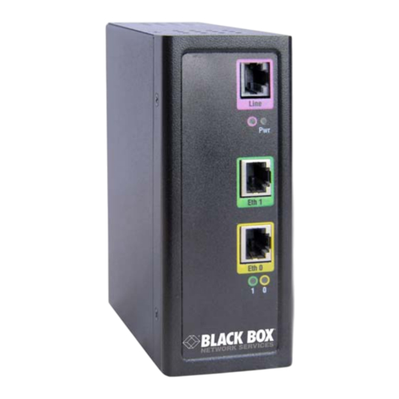
Black Box Ethernet Extenders 3. INSTALLATION Once the LB532A-L or LB532A-R is properly configured, it is ready to connect to the line interface and to the power source. This section explains how to make these connections. LB532A-L and LB532A-M front panel connectors Figure 3. -
Page 17: Connecting The Ethernet Interface
• 11,000 feet (2.2 miles or 3.5 km) at 5696 kbps per hop Two things are essential: 1. The LB532A-L model works with the LB532A-R model. Every local line port must connect to a remote line port. Local to remote connection Figure 4. -
Page 18: Connecting Power
+ and the negative lead into the opening on the terminal block labeled -. Tighten the screws on the block to secure the wires. The LB532A-L and LB532A-R power up as soon as it is connected to an AC power source—there is no power switch. -
Page 19: Operation
4.1 POWER-UP To apply power to the LB532A-L or LB532A-R, first be sure that you have read section 1.3, “Power Input Connector” on page 9, and that the unit is connected to the appropri- ate power source. -
Page 20: Power (Green)
1 to 2 minutes to complete. To upgrade the software: 1. Telnet to LB532A-L via the Eth 0 or Eth 1 port through the default IP address 192.168.200.1/24 or Telnet to LB532A-R via the Eth 0 or Eth 1 port through the default Ip address 192.168.200.2/24. -
Page 21: Specifications
A. SPECIFICATIONS A.1 LINE RATE 192 to 5696 kbps (64k increments; 3-89 timeslots) A.2 ETHERNET INTERFACE Two RJ-45, 10/100Base-T, IEEE 802.3 Ethernet A.3 STATUS LEDS Power (Green) The Power LED glows solid during normal operation. At startup, during the POST, the LED blinks once every second. -
Page 22: Power And Power Supply Specifications
A.5 POWER AND POWER SUPPLY SPECIFICATIONS The LB532A-L and LB532A-R comes with an external AC universal power supply. • The power connection to the LB532A-L and LB532A-R is a terminal block (see Figure 8) • There is one fuse in the equipment rated at 250V, 500 mA, 2 sec. -
Page 23: Environment
Operating temp: -40 to 185°F (-40 to 85°C) Relative Humidity: 8 to 90% non-condensing Altitude: 0 to 15,000 feet (0 to 4,600 meters) A.11 THIRD PARTY SOFTWARE LICENSES NOTE: The LB532A-L and LB532A-R includes software developed under third party licenses. B. INTERFACE PINOUTS B.1 LINE PORT... - Page 24 LB532A-L version 1...
Need help?
Do you have a question about the LB532A-L and is the answer not in the manual?
Questions and answers