Table of Contents
Advertisement
Quick Links
RuggedSwitch™ ™ ™ ™
RuggedSwitch
RuggedSwitch
RuggedSwitch
RS500
RS500
RS500
RS500
Installation Guide
Installation Guide
Installation Guide
Installation Guide
RuggedCom Inc.
30 Whitmore Road,
Woodbridge, Ontario
Canada L4L 7Z4
Web:
www.ruggedcom.com
Tel: (905) 856-5288
Fax: (905) 856-1995
Toll Free: (888) 264-0006
Advertisement
Table of Contents

Related Manuals for RuggedCom RuggedSwitch RS500


Summary of Contents for RuggedCom RuggedSwitch RS500
- Page 1 RuggedSwitch™ ™ ™ ™ RuggedSwitch RuggedSwitch RS500 RS500 RS500 RS500 Installation Guide Installation Guide Installation Guide Installation Guide RuggedCom Inc. 30 Whitmore Road, Woodbridge, Ontario Canada L4L 7Z4 Web: www.ruggedcom.com Tel: (905) 856-5288 Fax: (905) 856-1995 Toll Free: (888) 264-0006...
-
Page 2: Federal Communications Commission Radio Frequency Interference Statement
Operation of this equipment in a residential area is likely to cause harmful interference in which case the user will be required to correct the interference on his own expense. Warning: Changes or modifications not expressly approved by RuggedCom Inc. could void the user’s authority to operate the equipment. -
Page 3: Table Of Contents
Failsafe Relay Specifications................. 12 Networking Standards Supported ................12 Fiber Optical Specifications................... 13 Networking Performance Specifications ..............13 Type Test Specifications..................14 Operating Environment..................15 Physical Dimensions .................... 15 Agency Approvals ....................16 Warranty..........................16 © 2008 RuggedCom Inc. All rights reserved Rev101... -
Page 4: Product Overview
Radiated RF Immunity: 35V/m per ANSI/IEEE C37.90.2 Power supply options: 24VDC, 48VDC or 110VDC Failsafe output relay for critical failure or error alarming 4 – 10BaseFL (10Mbps) multimode 1 – 100BaseFX fiber optical port Full-duplex operation (no collisions) © 2008 RuggedCom Inc. All rights reserved Rev101... -
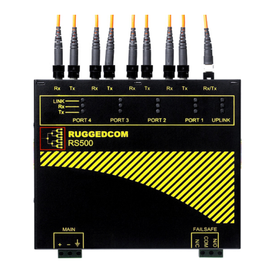
Page 5: Rs500 Front Panel Description
LINK LED (Yellow) Solid Link Established Blinking – Once per second Tx, Rx Activity Tx LED (Red) Blinking Tx (Transmit) Activity Rx LED (Green) Blinking Rx (Receive) Activity POWER LED (Red) Solid Power On © 2008 RuggedCom Inc. All rights reserved Rev101... -
Page 6: Rs500 Top And Bottom View
100BaseFX Port 10BaseFL Ports MTRJ Connector ST Connectors Safety Ground Bottom View Reset Stud Failsafe Output Relay DC(+) DC(-) DIN Rail Mounting Bracket Surge Ground Fig. 1.4.1 RS500 Top and Bottom View © 2008 RuggedCom Inc. All rights reserved Rev101... -
Page 7: Installation
2.1 DIN Rail Mounting RS500 DIN Rail Mounting & Release Front View Side View DIN RAIL DIN RAIL Mounting Latch DIN RAIL Release Slot Release Direction Release Action Screw Driver Fig. 2.1.1 RS500 Rail Mounting © 2008 RuggedCom Inc. All rights reserved Rev101... -
Page 8: Power Supply Wiring And Grounding
RS500. Surge Ground is connected directly to the safety ground terminal internally. NOTE: Since the Chassis Ground is connected to the equipment ground bus internally, HIPOT testing cannot be performed in the field. © 2008 RuggedCom Inc. All rights reserved Rev101... -
Page 9: Power Supply - Dc Input
Fig. 2.2.2 Power Supply – DC Input Note: Ground bus can either be connected to the Ground Stud on the rear of the RS500 chassis, or the Surge Ground port on the screw-in terminal block. © 2008 RuggedCom Inc. All rights reserved Rev101... -
Page 10: Hipot (Dielectric Strength) Testing
HIPOT Dielectric strength testing cannot be performed in the field due to transient/surge suppression circuitry connected to the RS500 Surge/Chassis Ground. All RuggedSwitch products are HIPOT tested according to IEC 60255-5 (Section 6) during final test. © 2008 RuggedCom Inc. All rights reserved Rev101... -
Page 11: Failsafe Output Wiring And Specifications
RS500. The contacts are energized upon power up of the unit and remain energized until a critical error occurs. RS500 Failsafe Relay Outputs Normally Closed Common Normally Open *** Normal contact state prior to power being applied to unit. *** © 2008 RuggedCom Inc. All rights reserved Rev101... -
Page 12: Technical Specifications
0.3A @ 30VAC 1A @ 30VDC, 0.3A @ 80VDC 3.3 Networking Standards Supported Parameter 10Mbps Ports 100Mbps Ports Notes IEEE 802.3 10BaseT / 10BaseFL IEEE 802.3u 100BaseTX / 100BaseFX IEEE 802.3x Full Duplex Operation © 2008 RuggedCom Inc. All rights reserved Rev101... -
Page 13: Fiber Optical Specifications
Parameter 10Mbps Ports 100Mbps Ports Notes (10BaseFL) (100BaseFX) Latency 16us + frame time 5us + frame time Filtering Rate 14 880 148 800 Frames/sec MAC Address Table 8192 VLAN Address Table 4096 © 2008 RuggedCom Inc. All rights reserved Rev101... -
Page 14: Type Test Specifications
IEC 60068-2-1 -40°C Test Ad: 16 hrs @ -40°C Temperature (Dry Heat) IEC 60068-2-2 85°C Test Bd: 16 hrs @ 85°C Humidity IEC 60068-2-30 Non-condensing Test Db: 6 cycles, 55°C, 95% Humidity © 2008 RuggedCom Inc. All rights reserved Rev101... -
Page 15: Operating Environment
-40 to 85°C Temperature measured from a 30cm radius surrounding the center of the R500 enclosure. Ambient Relative Humidity 5% to 95% Non-condensing Ambient Storage -40 to 85°C Temperature 3.8 Physical Dimensions © 2008 RuggedCom Inc. All rights reserved Rev101... -
Page 16: Agency Approvals
EN 61000-6-2 FCC Part 15, Class A Approved 4 Warranty RuggedCom warrants this product for a period of five (5) years from date of purchase. For warranty details, visit http://www.ruggedcom.com/ or contact your customer service representative. Should this product require warranty or service contact the factory at: RuggedCom Inc.
Need help?
Do you have a question about the RuggedSwitch RS500 and is the answer not in the manual?
Questions and answers