Table of Contents

Related Manuals for CBC PT110N


Summary of Contents for CBC PT110N
-
Page 1: User Manual
Vandal Resistant 10x PTZ Dome User Manual NY: 55 Mall Drive • Commack, NY 11725 (800) 422-6707 CA : 20521 Earl Street • Torrance, CA 90503 (800) 888-0131 www.computarganz.com... -
Page 2: Table Of Contents
CONTENTS ○ Introduction Features Product & Accessories Parts Name & Functions ○ Installation DIP Switch Setup Installation using Ceiling Mount Bracket Installation using Wall Mount Bracket Installation using Flush Mount Bracket Cabling ○ Operation Check Points before Operation Preset and Pattern Function Pre-Check Starting OSD Menu Reserved Preset Preset... -
Page 3: Introduction
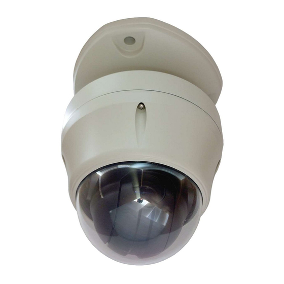
INTROD UCTION Features Camera Specifications CCD Sensor : 1/4" Interline Transf er CCD Zoom Magnification : × 10 Optical Zoom, × 10 Digital Zoom (Max × 100 Zoom) Day & Night Function Variable Focus Mode: Auto-F ocus / Manual Focus / Semi-Auto Focus. Independent &... - Page 4 OSD menu. For more information, refer to “Reserved Preset” in this manual. IP66 (weather resistant) *(PT110N-XT model only). This product has been certified to the IP66 standard for waterproof and spray proof environments. Also...
-
Page 5: Product & Accessories
INTRODUCTION Product & Accessories PT110N-XT model (outdoor). Product & Accessories- Main Body Mount Adapter Gasket(Rubber) Terminal Block Screws Six angles wrench Video cable Options Wall Mount Bracket Ceiling Mount Bracket Sun shield Speed Dome Camera Instruction Manual Speed Dome Camera Instruction Manual... - Page 6 INTRODUCTION PT110N model (indoor) Product & Accessories- Main Body Surface Mount Bracket Screws & Terminal Block Options In-Ceiling Mount Bracket Ceiling Mount Bracket Wall Mount Bracket Speed Dome Camera Instruction Manual...
-
Page 7: Parts Name & Functions
INTRODUCTION Parts Name & Functions Mount Adapter Cabling Terminal Block Safety Retention Spring Main Body Gasket (PT110N- XT Model only) Lock-up Screw DIP Switch Dome Cover Main Unit / Surface Mount Bracket Back of Main Unit Dome Cover Do not remove protecti ve vinyl from dome cover before finishing al installation processes to protect dome cover from scratches or dust. -
Page 8: Installation
INSTALLATION DIP Switch Setup Before you install the camera, you should set the DIP switches to configure the camera ID and communication protocol. Camera ID Setup The ID number of camera is set using a binary number. Examples shown below. The range of ID is 1~255. - Page 9 INSTALLATION Communication Protocol Setup Select the approp riate Proto col with DIP switch combination. Switch St te Protocol (Pin 1) (Pin 2) PELCO-D, 2400 bps PELCO-D, 9600 bps PELCO-P, 4800 bps PELCO-P, 9600 bps If you want to control using DVR or P/T controller, their protocol must be identical to camera.
- Page 10 INSTALLATION Pin 3 is only for supplier, DO NOT CHANGE THESE ITS ORIGINAL STATE. If you change one of these, proper operation can not be achieved. Pin 3 PAL / NTSC system selection of Camera. DO NOT CHANGE THIS PIN. Terminal Resistor Setup Terminal resistor is used if your system meets one of following two conditional cases.
-
Page 11: Installation Using Ceiling Mount Bracket
INSTALLATION INSTALLATION INSTALLATION Installation using Ceiling Mount Brack t e ① After putting t ② Wire cables to he Gask on the ceiling termin als and connect the terminals to main unit. Do not use surface mount sten ceil g mount brac et t cei ng with 3 b acke ! screws. -
Page 12: Installation Using Wall Mount Bracket
Installation using W l a l Mount Bracket ② Wire cables to terminals and connect the ① After putting the Gasket on the wa terminals to main unit. Do not use surface Fasten wall mount bracket to ceiling with 4 mount bracket! screws. -
Page 13: Installation Using Flush Mount Bracket
INSTALLATION Installation using Flush Mount Bracket ① ② C t holes in ceiling Alig n main body bracket with flush mount bracket. Fasten with screws. ③ ④ Connect fall-proof spring to main body Put main body and bracket assembly into hook. -
Page 14: Cabling
Please check the voltage and current capacity of rated power carefully. Rated power is indicated on the back of main unit. Rated Power Input Voltage Range Current Consumption AC 24V (PT110N) AC 17V ~ 29V 0.4 A AC 24V (PT110N-XT) AC 17V ~ 29V 1.5 A... - Page 15 INSTALLATION Vid o o nection e C n Connect with BNC coaxial c able. Alarm Input Connection Sensor Input Internal SENSOR IN1 SENSOR COM (GND) SENSOR IN2 SENSOR COM (GND) SENSOR IN3 SENSOR COM (GND) SENSOR IN4 SENSOR COM (GND) Before connecting sensors, check the sensor driver voltage and output signal type.
- Page 16 INSTALLATION If you want to use Alarm Input, the type of sensor must be selected in OSD menu. The sensor types are Normal Open and Normal Close. If the sensor type is not selected properly, alarm activation will occur opposite of what is desired. Normal Open Output Voltage is high state when sensor is activated Normal Close...
-
Page 17: Operation
OPERATION Check Points before Operation Before power is applied, please check the cables carefully. The camera ID of the controller must be identical to that of the target camera. The camera ID can be checked by reading DIP switch o f the camera. -
Page 18: Starting Osd Menu
OPERATION Starting OSD Menu Function Using the OSD menu, Preset, Pattern, Swing, Group and Alarm Input function can be configured f or each application Enter M <G o Prese t> [95] Reserved Preset Description Some Preset numbers are reserved to special functions. Function Go Preset [95] : Enters into OSD menu... -
Page 19: Preset
OPERATION Preset Function Max. 127 positions can be stored as Preset position. The Preset number can be assigned from 1 to 128, but 95 is reserved for starting OSD menu. Camera char acteristics (i.e. White Balance, Auto Exposure) can be set up independently for each preset. -
Page 20: Pattern
OPERATION Pattern Function Pattern Function allows the camera to memorize a path (often a curved path) created by controller joystick for an assigned time. The camera will then retrace the path exactly as memorized. 4 Patterns are available and Maximum 1200 communication commands can be stored in a pattern. -
Page 21: Group
OPERATION Group Function The group function allows a running sequence of Presets, Pattern and/or Swings. Max 8 groups can be stored. Each group can have max 20 action entities which can be preset, pattern or swing. Preset speed can be set up and the repeat number of Pattern &... -
Page 22: Other Functions
OPERATION Other Functions Power Up Action This function enables the camera to resume the last action executed before power down. Most actions such as Preset, Pattern, Swing and Group are available for this function, but Jog actions c annot be resumed. Auto Flip If the tilt angle arrives at the top of tilt orbit (90°), zoom module camera will keep moving in the... -
Page 23: Osd Display Of Main Screen
OPERATION OSD Display of Main Screen Action Title Preset Label LABEL12345 PRESET1 Image Flip Alarm Information I:1--4 Camera ID CAM 1 15/4/x1/N P/T/Z Information P/T/Z Information Current Pan/Tilt angle in degree, zoom magnif ication and a compass direction. Camera ID Current Camera ID (Address). -
Page 24: How To Use Osd Menu
HOW TO USE OSD MENU General Rules of Key Operation for Menu The menu items surr ounded with ( ) always have a sub menu. At all menu levels, to go into sub menu, press NEAR key. To go to up one menu level, press FAR key. -
Page 25: Display Setup
HOW TO USE OSD MENU Display Setup This menu defines Enable/Disable of OSD display on Main Screen. If an DISPLAY SETUP item is set to be AUTO, the item is displayed only when the value of it is ------------------------ CAMERA ID changed. -
Page 26: Privacy Zone Mask Setup
HOW TO USE OSD MENU Privacy Zone Mask Setup Select area in image to mask. PRIVACY ZONE ---------------------- MASK NO Mask No [1~4] UNDEFINED DISPLAY Select Mask number. If the selected mask has CLEAR MASK CANCEL already data, camera moves as it was set. <EDIT MASK>... -
Page 27: Camera Setup
HOW TO USE OSD MENU Camera Setup Setup the general functions of zoom camera module. ZOOM CAMERA SETUP ------------------------ Focus Mode [AUTO/MANUAL/SEMIAUTO] FOCUS MODE SEMIAUTO DIGITAL ZOOM Sets camera focus mode. LINE LOCK IMAGE FLIP SEMIAUTO Mode <WHITE BALANCE SETUP> <AUTO EXPOSURE SETUP>... - Page 28 HOW TO USE OSD MENU White Balance set up WB SETUP - GLOBAL WB Mode [AUTO/MANUAL] ------------------------ WB MODE AUTO In Ma nual mode, Red and Blue level can be ADJUST up manually BLUE ADJUST Red Adjust [10~60] Blue Adjust [10~60] BACK EXIT...
- Page 29 HOW TO USE OSD MENU A t E pos u o x ure Setup Backlight [ON/OFF] Sets Backlight Compensation AE SETUP - GLOB --------------- ------ Day/Night [AUTO1/AUTO2/DAY/NIGHT BACKLIGHT DAY/NIGHT AUTO1 AUTO1 exchanges Day/Nig ht mode faster BRIGHTNESS IRIS AUTO than AUTO2. SHUTTER RMAL Brightness...
-
Page 30: Motion Setup
HOW TO USE OSD MENU Motion Setup Setup the general functions of P an/Tilt motions. MOTION SETUP ------------------------ MOTION LOCK Motion Lock /OFF] PWR UP ACTION AUTO FLIP If Motion Lock is set to ON, it is impossible to JOG MAX SPEED 120/SEC set up and delete Preset, Swing, Pattern and JOG DIRECTION... - Page 31 HOW TO USE OSD MENU Parking Action Setup If Park Enable is set to ON, camera runs assigned function automatically PARKING ACTION SETUP ------------------------ f there is no PTZ comman d during assigned "Wait Time". PARK ENABLE WAIT TIME 00:10:00 Park Enable ON/OFF] PARK ACTION...
-
Page 32: Preset Setup
HOW TO USE OSD MENU Preset Setup Preset Number [1~128] PRESET SETUP ------------------------ a selected preset is already defined, camera PRESET NO. moves to pre-defined position and preset CLR PRESET CANCEL aracteristics such as Label and Relay Outputs <EDIT SCENE> <EDIT LABEL>... -
Page 33: Swing Setup
HOW TO USE OSD MENU Swing Setup Swing Number [1~8] SWING SETUP ------------------------ Select Swing number to edit. If a selected Swing is SWING NO. 1ST POS. NOT USED not def ined, "NOT USED" is displayed in 1st 2ND POS. NOT USED Position and 2nd Position SWING SPEED... -
Page 34: Pattern Setup
HOW TO USE OSD MENU Pattern Setup Pattern Number [1~4 ] PATTERN SETUP ------------------------ Selects Pattern number to edit. PATTERN NO. UNDEFINED If a selected pattern number is not defined, CLR PATTERN CANCEL <EDIT PATTERN> "UNDEFINED" will displayed under selected pattern number. Clear Pattern [CANCEL/OK] BACK... -
Page 35: Group Setup
HOW TO USE OSD MENU Group Setup Group Number [1~8] GROUP SETUP ------------------------ Selects Group number to edit. GROUP NO. UNDEFINED If a selected Group number is not defined, CLEAR GROUP CANCEL <EDIT GROUP> "UNDEFINED" will be displayed under selected Group number. - Page 36 HOW TO USE OSD MENU ④ Set up items such as Action, ###, Dwell and OPT. E IT GRO P ------------------------ NO ACTION ### DWELL OPT ------------------------ 1 PRESET 1 00:03 360 2 NONE 3 NONE 4 NONE 5 NONE ------------------------ SAVE :MOVE CURSOR]...
-
Page 37: System Initialize
HOW TO USE OSD MENU System Initialize Clear All Data Deletes all configuration data, such as display, SYSTEM INITIALIZE camera, and motion setup. ------------------------ CLEAR ALL DATA CLR DISPLAY SET Clear Display Set Initializes Display Configuration CLR CAMERA SET CLR MOTION SET CLR EDIT DATA Clear Camera Set Initializes Cam... -
Page 38: Specifications
Standard Sun shield * PT110N-XT Model Only Note: PT110N-XT. PT110N appearance will vary, see ** Check the voltage and current capacity of rated power carefully. page 38 for PT110N appearance specifications. *** Specifications of this product are subject to change without notice. -
Page 39: Dimensions
SPECIFICATIONS Dimensions-PT110N Indoor Model M in U it n & Surface Mount Bracket Ceiling Mount Bracket Wall Mount Bracket U nit: mm Speed Dome Camera Instruction Manual... - Page 40 SPECIFICATIONS Dimensions-PT110N-XT Outdoor Model Ceiling Mount Bracket Sun shield Wall Mount acket Unit: mm Speed Dome Camera Instruction Manual...
- Page 41 NOT S Speed Dome Camera Instruction Manual...
Need help?
Do you have a question about the PT110N and is the answer not in the manual?
Questions and answers