Yamaha PJP-EC200 User Manual
Conference echo canceller
Hide thumbs
Also See for PJP-EC200:
- Specfications (2 pages) ,
- Setup procedure (14 pages) ,
- Installation and setup manual (2 pages)
Table of Contents
Advertisement
Quick Links
Advertisement
Table of Contents

Related Manuals for Yamaha PJP-EC200


Summary of Contents for Yamaha PJP-EC200
- Page 1 EC200 Conference Echo Canceller User's Manual...
- Page 2 Yamaha will not tity of power. be held responsible for any damage resulting from use of this unit with a voltage other than specified.
-
Page 3: Table Of Contents
Contents INTRODUCTION OPERATIONAL MANAGEMENT Contents ..................3 Maintenance and Management ..........35 Introduction ................4 Checking configurations and status ........35 Check the latest information.............4 Checking the configuration information........ 35 About this manual ..............4 Checking the system logs ............38 CONFIRMATION SOFTWARE LICENSE Checking the error history ............. -
Page 4: Introduction
• Specifications of this unit or the web menu and contents of this document are subject to change without notice. • Yamaha does not accept any liability for any loss or damage resulting from any use of this unit. The warranty covers a repair of this unit... -
Page 5: Confirmation Software License Agreement
1-1 herein, into the PRODUCT or personal computer owned by you. 1. GRANT OF LICENSE: 1-1. YAMAHA grants you a personal non-exclusive license to install the SOFTWARE and use the SOFTWARE on the PRODUCT or other devices, including but not limited to the personal computer, which you own. - Page 6 Government End Users shall acquire the Software with only those rights set forth herein. 9. ACKNOWLEDGMENT: You agree that this AGREEMENT is the complete and exclusive statement of agreement between you and YAMAHA concerning the subject matter hereof and supersedes all proposals or prior agreements, verbal or written, and any other communications between you and the parties relating to the subject matter hereof.
-
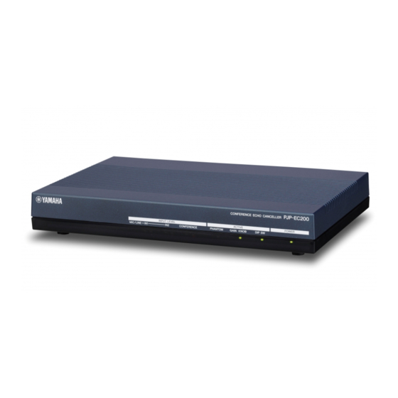
Page 7: About The Product
About the Product The PJP-EC200 is a high-performance echo canceller box that enables smooth simultaneous talk during a videoconference or a webconference. Echo canceller x 2 CONFERENCE OUT L CONFERENCE OUT R Mixer CONFERENCE IN L CONFERENCE IN R Feedback suppressor x 2... -
Page 8: Controls And Functions
Controls and Functions Front panel PJP-EC200 CONFERENCE ECHO CANCELLER INPUT LEVEL ACTIVE POWER MIC/LINE CONFERENCE PHANTOM GAIN KNOB DIP SW LEDs Label Light to indicate the status of this unit. The following information is shown. • MODEL No.: Model number of this unit •... -
Page 9: Rear Panel
Rear panel STANDBY ON AUTO ETHER LINE OUTPUT CONFERENCE MIC/LINE INPUT ANALYZER GAIN INITIALIZE PHANTOM DIP SW DC IN 12V ACTIVE ACTIVE AUTO ANALYZER ETHER Press this switch to adjust the echo canceller and feedback Use to connect a LAN cable. The LINK LED (left) and the suppressor automatically. - Page 10 ■Functions of the DIP switch PHANTOM (DC+48V) Note Turns on/off the phantom power. ON: Turn on the phantom power. The signal level differs between MIC level and LINE level. When OFF: Turns off the phantom power. you connect a device to a MIC jack, set this switch to MIC. When you connect a device to a LINE jack, set this switch to LINE.
-
Page 11: Installation And Initial Setup
Installation and Initial Setup This section describes connections and setup required for using this unit. The basic setup of this unit is available only with the DIP switch. For advanced setup, refer to “Using the Web Menu” (page 16). Notes •... -
Page 12: Configure The Settings Of This Unit Using
Configure the settings of this unit using the DIP switch. For details, refer to “Functions of the DIP switch” (page 10). Turn on the external devices. Turn on this unit. The POWER LED on the front panel turns on. On your PC or videoconference system, adjust the output level. -
Page 13: Using In Combination With A Pa System
Using in combination with a PA system By combining this unit with a PA system, it makes possible to use many microphones for a conference. STANDBY ON AUTO ETHER LINE OUTPUT CONFERENCE MIC/LINE INPUT ANALYZER GAIN INITIALIZE PHANTOM DIP SW DC IN 12V ACTIVE ACTIVE... - Page 14 On your PA system, adjust the input gain. For details, refer to the owner's manual supplied with your PA system. Use GAIN to adjust the input gain for MIC/LINE INPUT. Adjust the input gain so that the INPUT LEVEL LED on the front panel does not turn on in red.
-
Page 15: Automatic Setup By Auto Analyzer
Automatic Setup by Auto Analyzer The auto analyzer function automatically sets the echo Notes canceller and feedback suppressor settings best suited for your environment (types of microphone and speakers, size • During the measurement, the microphone picks up test tones of conference room, etc.). -
Page 16: Using The Web Menu
Using the Web Menu By using the web menu, you can configure this unit's settings in more detail. The web menu is accessible from the PC connected to this unit. To configure this unit's settings from the web menu, set the DIP switch (DIP SW) to ETHER. Notes •... -
Page 17: Setting The Password
The "System Settings" screen appears. In the "Login Password" field, click "Edit". The "Connect to 192.168.100.101" screen appears. Enter "pjp-ec200" in the "User name" field and the password you have set in step 3 in the "Password" field and then click "OK". -
Page 18: Setting The Date And Time
The "System Settings" screen appears. In the "Clock" field, click "Edit". The "Clock Settings" screen appears. In the "PJP-EC200 Date/Time" field, select "Change" and then enter the date and time. To set the exact time, enter a time a little ahead and then... -
Page 19: Setting The Date And Time Automatically
If your area uses DST (Daylight Saving Time) Setting the date and time Select "Adjust clock for daylight saving changes" and then automatically configure the DST setting. You can set the date and time of this unit automatically by Adjust automatically: Adjust DST automatically using an NTP server via the Internet. - Page 20 Select when to connect to the NTP server for clock synchronization. Inquiry time at startup: Synchronize the clock at startup of this unit. Inquiry time at: Synchronize the clock at a specified time. If you select "Inquiry time at", select a day to synchronize the clock.
-
Page 21: Configuring The Network Settings
Configuring the Network Settings 1. Specifying an IP address of this Click on the link to access to the new IP unit's LAN port address and then click "Close". According to the LAN environment where this unit is used, configure the IP address netmask settings of this unit. -
Page 22: Specifying A Default Gateway
2. Specifying a default gateway Click "Close". Follow the procedure below to specify a default gateway for this unit. Click "IP Settings". The "IP Settings" screen appears. In the "Default Gateway" field, click "Edit". The "IP Settings" screen appears again. The "Default Gateway Settings"... -
Page 23: Specifying A Dns Server
3. Specifying a DNS server Click "Close". Follow the procedure below to specify a DNS server for this unit. Click "IP Settings". The "IP Settings" screen appears. In the "DNS Server" field, click "Edit". The "IP Settings" screen appears again. The "DNS Server Settings"... -
Page 24: Limiting Access To The Web Menu
Limiting Access to the Web Menu You can limit access to the web menu by PC's IP address or permit access to the web menu only from PCs in the same network. Click "System Settings". Click "Apply". The "System Settings" screen appears. The confirmation screen appears. -
Page 25: Controlling Echoes
Controlling Echoes Follow the procedure below to configure the echo reduction level according to your environment. You can configure the settings for MIC/LINE IN1 and IN2 individually. Use: Select whether to use the echo canceller. To use the echo canceller, select "Enable". Click "Sound Settings". -
Page 26: Controlling Acoustic Feedback
Controlling Acoustic Feedback Follow the procedure below to configure the acoustic feedback reduction level according to your environment. You can configure the settings for MIC/LINE IN1 and IN2 individually. Use: Select whether to use the feedback suppressor. To use the feedback suppressor, select "Enable". Click "Sound Settings". -
Page 27: Controlling Noises
Controlling Noises Follow the procedure below to configure the noise reduction level according to your environment. You can configure the settings for MIC/LINE IN1 and IN2 individually. Click "Sound Settings". Click "Apply". The "Sound Settings" screen appears. The confirmation screen appears. In the "Noise Reduction"... -
Page 28: Adjusting The Input Gain Automatically (Auto Gain Controller)
Adjusting the Input Gain Automatically (Auto Gain Controller) If you are using a boundary microphone, the volume level of sounds picked up by the microphone varies depending on the distance between the microphone and talker. By configuring the auto gain controller settings, this unit automatically optimizes the pickup gain according to the volume level of pickup sounds. -
Page 29: Adjusting The Input Gain For Mic/Line Input
Adjusting the Input Gain for MIC/LINE INPUT If the volume level of sounds picked up by the microphone is too high, the sounds cannot be handled by this unit and will be distorted. In this case, you need to adjust the input gain so that the INPUT LEVEL LED does not turn on in red. You can configure the settings for MIC/LINE IN1 and IN2 individually. -
Page 30: Adjusting The Volume Level
Adjusting the Volume Level Follow the procedure below to adjust the volume levels of the microphone and speakers connected to this unit. Click "Sound Settings". The "Sound Settings" screen appears. In the "Level" field, click "Edit". The "Level Settings" screen appears. Configure the volume level of each device. -
Page 31: Using The Internal Mixer
Using the Internal Mixer You can select whether to output audio input through MIC/LINE to LINE OUTPUT. You can configure the settings for MIC/LINE IN1 and IN2 individually. Click "Sound Settings". Click "Close". The "Sound Settings" screen appears. In the "Mixer" field, click "Edit". The "Mixer Settings"... -
Page 32: Configuring The Phantom Power Settings
Configuring the Phantom Power Settings If the DIP switch (PHANTOM) is set to ON, you can select whether to supply the phantom power thorough Configure the phantom power settings. MIC/LUNE IN1 and IN2. Do not turn on the phantom power when a device which does not require a phantom power is connected to MIC/ LINE INPUT. -
Page 33: Configuring This Unit's Settings Automatically (Auto Analyzer)
Configuring This Unit's Settings Automatically (Auto Analyzer) The auto analyzer function automatically sets the echo canceller and feedback suppressor settings best suited for your environment (types of microphone and speakers, size of conference room, etc.). Click "Sound Settings". The "Sound Settings" screen appears. In the "Special Function"... -
Page 34: Turning On/Off The Audio Guidance
Turning On/Off the Audio Guidance Follow the procedure below to turn on/off the audio guidance which notifies you of events during the auto analyzer process. Also, you can set the volume level of the audio guidance. Click "System Settings". Click "Close". The "System Settings"... -
Page 35: Maintenance And Management
Maintenance and Management You can use various maintenance and management features of this unit with the web menu. Checking configurations and status Checking the configuration information You can output a report that shows the configurations and status of this unit as a text file. This unit internally manages configuration information with a config file. - Page 36 ■Saving the configuration information on ■Saving the configuration information on your PC this unit Follow the procedure below to save the current Follow the procedure below to save the current configurations as a text file. configurations on this unit. You can save up to three sets of configurations.
- Page 37 ■Recalling configurations saved on this Enter a comment and then click "Apply". unit You can input a comment if necessary. The comment will be displayed under "Save Time" in the "Save/ In the "Save/Load Configuration" Load Configuration" screen. screen, click "Load" next to the desired memory number.
-
Page 38: Checking The System Logs
Host Address: Specify where to save log files. Select Checking the system logs "Specify" and then enter a destination IP address. DEBUG: Select whether to output information about This unit records the operation history as system logs the internal processing of this unit. (SYSLOG). - Page 39 ■Viewing the system logs Follow the procedure below to display the system logs (up to 500 lines) on the PC monitor. In the web menu, click "Maintenance". The "Maintenance" screen appears. In the [SYSLOG Management] - [Output SYSLOG to Window] field, click "Execute".
- Page 40 In the [SYSLOG Management] - [Delete SYSLOG] field, click "Execute". The "Save SYSLOG" screen appears. Click "Save". The "Delete SYSLOG" screen appears. Click "Delete". The confirmation screen appears. Click "Close". The confirmation screen appears. Click "Close". The "Maintenance" screen appears again. ■Deleting the system logs Follow the procedure below to delete the current system The "Maintenance"...
-
Page 41: Checking The Error History
■Saving the error history on your PC Checking the error history Follow the procedure below to save the error history as a CVS file. You can check the history of errors occurred on this unit. This may bring an early solution to system problems. You can save the error history which you can view by ■Viewing the error history carrying out "Viewing the error history". - Page 42 ■Saving the error history on this unit Click "Close". Follow the procedure below to save the error history to this unit's built-in flash memory. In the web menu, click "Maintenance". The "Maintenance" screen appears. In the [Error History Management] - [Save Error History] field, click "Execute".
- Page 43 Select an interval to automatically save the error history and then click "Apply". The confirmation screen appears. Click "Close". The "Delete Error History" screen appears. Click "Delete". The "Maintenance" screen appears again. ■Deleting the error history Follow the procedure below to delete the current error history.
-
Page 44: Special Functions
Special Functions Protecting the settings Click "Close". You can protect the settings of this unit. In the web menu, click "Maintenance". The "Maintenance" screen appears. In the [Special Functions] - [Config Protection] field, click "Execute". The protection is enabled and the "Maintenance" screen appears again. -
Page 45: Restarting This Unit
Restarting this unit Click "Close". You can forcibly quit all the operations in process and restart this unit. In the web menu, click "Maintenance". The "Maintenance" screen appears. In the [Special Functions] - [Restart] field, click "Execute". The unit restarts. The "Restart"... -
Page 46: Changing The Screen Color
Changing the Screen Color You can change the screen color of the web menu. In the web menu, click a desired color chip. The screen color changes. -
Page 47: Using The Latest Features
Using the Latest Features You can download the firmware (program to control the functions of this unit) to use the latest features. There are two ways to update the firmware of this unit: One way is that you connect this unit to the Internet and automatically install the latest firmware (page 47). -
Page 48: Configuring The Http Revision-Up Settings
The firmware update process takes a few minutes Configure the automatic firmware update settings. During the firmware update process, the LEDs turn on in rotation. Never turn off this unit while the LEDs are turned When the firmware update is complete This unit restarts automatically. -
Page 49: Updating The Firmware Manually
The firmware update process takes a few minutes Projectphone website: During the firmware update process, the LEDs turn on in http://www.yamaha.co.jp/english/product/ rotation. Never turn off this unit while the LEDs are turned projectphone/ When the firmware update is complete Permit access to the TFTP server. -
Page 50: Troubleshooting
• “Q2: Web menu settings are not available” (page 52) • “Q3: Have an audio problem” (page 53) • “Q4: Other problems” (page 54) If the problem you are experiencing is not listed or if the instruction does not help, contact the nearest authorized Yamaha dealer or service center. -
Page 51: Q1: Leds Are Off Or Blinking
Q1: LEDs are off or blinking Problem Cause Remedy No LEDs turn on. This unit is not turned on. Set the power switch to on. The power cable is not connected to the AC Check that the power cable is connected to the AC outlet outlet. -
Page 52: Q2: Web Menu Settings Are Not Available
The user box is blank on the "Network Some web browsers require entering your user name to the web browser for logging Password" screen. save the password. In this case, enter "pjp-ec200" as a in to the web menu. username. A login prompt appears even A login prompt will appear even if no Enter "pjp-ec200"... -
Page 53: Q3: Have An Audio Problem
Q3: Have an audio problem Problem Cause Remedy The audio from the PC or The input level setting is incorrect. Configure the input level setting on the device connected videoconference system to this unit. cannot be heard or is The input level of CONFERENCE IN is too Increase the input level. -
Page 54: Q4: Other Problems
Q4: Other problems Problem Cause Remedy • Check that the settings match the NTP server Cannot synchronize the The IP address or domain name of the NTP clock with an NTP server. sever is incorrect. information. • Ping the NTP server to confirm that it is functioning. A route to connect with the specified NTP Check the Internet service provider settings or route server has not been set. -
Page 55: List Of Error Messages
List of Error Messages Patterns of front LEDs Error type MIC/LINE CONFERENCE PHANTOM GAIN KNOB DIP SW Blink green/red Blink green, Blink green Blink green Blink green Detects a problem during On red system startup. Blink green/red Blink green, Blink green, Blink green Blink green Firmware update failed. -
Page 56: Resetting The Settings Of This Unit
Resetting the Settings of This Unit Resetting all settings You can reset the web menu settings and settings internally saved in this unit to the default. Notes Please note the followings when you reset the settings of this unit. • This operation will disconnect all the calls being connected. •... -
Page 57: Support Information
Support Information In case you are in need of support, visit the following website or contact the nearest authorized Yamaha dealer or service center. ■Checking log information and setting configurations A Yamaha representative may ask for log (SYSLOG) or configuration (config) information in order to understand the situation. -
Page 58: Specifications
Specifications General specifications Dimensions (W x H x D): Noise reduction: 270 mm x 42.6 mm x 180 mm 17 dB maximum (10-5/8" x 1-3/4" x 7-1/8") Interfaces: Weight: LINE OUTPUT (L/R): Stereo RCA pin-jacks 850 g (1.9 lbs) CONFERENCE (IN/OUT): Stereo mini jacks MIC/LINE INPUT: XLR/PHONE combo jacks Power supply: 2ch (48-V phantom power supply supported) -
Page 59: Input Specifications
Input specifications Input level Input Terminal Specification Maximum impedance Rated input level input level XLR, balanced type IN1&2 (MIC) -60 dBµ to -20 dBµ -6 dBµ 3 kΩ 50 to 600 Ω XLR, balanced type IN1&2 (LINE) -30 dBµ to +10 dBµ +20 dBµ... - Page 60 (February 2010, 3rd edition)
Need help?
Do you have a question about the PJP-EC200 and is the answer not in the manual?
Questions and answers