
Related Manuals for Speco VIP2B3


Summary of Contents for Speco VIP2B3
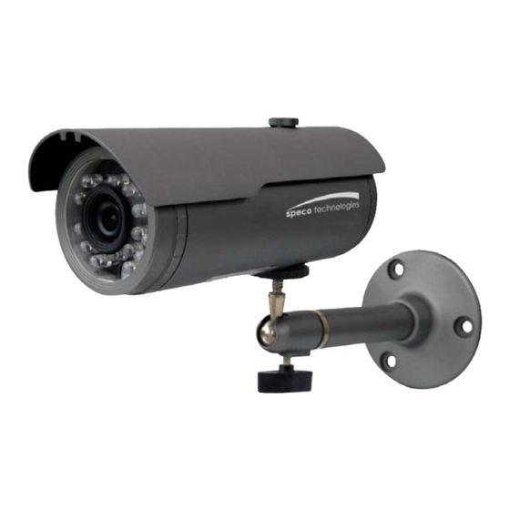
- Page 1 INSTRUCTION MANUAL VIP2B3 Full-HD IP IR Mini Bullet Please read this manual thoroughly before use, and keep it handy for future reference.
- Page 2 WARNING TO REDUCE THE RISK OF FIRE OR ELECTRIC SHOCK, DO NOT EXPOSE THIS PROCUCT TO RAIN OR MOISTURE. DO NOT INSERT ANY METALLIC OBJECT THROUGH THE VENTILATION GRILLS OR OTHER OPENNINGS ON THE EQUIPMENT. Apparatus shall not be exposed to dripping or splashing and that no objects filled with liquids, such as vases, shall be placed on the apparatus.
-
Page 3: Fcc Compliance Statement
FCC COMPLIANCE STATEMENT INFORMATION TO THE USER : THIS EQUIPMENT HAS BEEN TESTED AND FOUND TO COMPLY WITH THE LIMITS FOR A CLASS A DIGITAL DEVICE, PURSUANT TO PART 15 OF THE FCC RULES. THESE LIMITS ARE DESIGNED TO PROVIDE REASONABLE PROTECTION AGAINST HARMFUL INTERFERENCE WHEN THE EQUIPMENT IS OPERATED IN A COMMERCIAL ENVIRONMENT. -
Page 4: Important Safety Instructions
IMPORTANT SAFETY INSTRUCTIONS 1. Read these instructions. 2. Keep these instructions. 3. Heed all warnings. 4. Follow all instructions. 5. Do not use this apparatus near water. 6. Clean only with dry cloth. 7. Do not block any ventilation openings. Install in accordance with the manufacturer’s instructions. -
Page 5: Table Of Contents
Contents 1. Description ------------------------------------------------------------------6 1.1 Components - ------------------------------------------------------------------------------------------ 6 1.2 Key Features - ------------------------------------------------------------------------------------------ 7 1.3 Over View ---- ------------------------------------------------------------------------------------------ 8 1.4 Camera Adjustment------------------------------------------------------------------------------------ 9 2. Installation ----------------------------------------------------------------- 10 2.1 Network Connection------- ---------------------------------------------------------------------------- 10 2.2 IP Assignment ----------------------------------------------------------------------------------------- 12 3. Operation -------------------------------------------------------------------- 13 3.1 Access from a browser -------------------------------------------------------------------------------- 13 3.2 Access from the internet ------------------------------------------------------------------------------ 14 3.3 Setting the admin password over a secure connection ------------------------------------------- 14... -
Page 6: Description
1. Description The Network Camera supports the network service for a sensor image with progressive scan, which can be monitored on a real-time screen regardless of distances and locations. By using its dedicated program, many users are able to have an access to the Network Camera at once or a single user can monitor various network cameras at the same time. -
Page 7: Key Features
1.2 Key Features • Brilliant video quality The Network Camera offers the highly efficient H.264 video compression, which drastically reduces bandwidth and storage requirements without compromising image quality. Motion JPEG is also supported for increased flexibility. • Dual or triple streams The Network Camera can deliver dual or triple video streams simultaneously at full frame rate in all resolutions up to Full-HD(1920 x 1080p) using Motion JPEG and H.264 (or MPEG-4). -
Page 8: Overview
1.3 Overview • Connection Cable Wire Color Description Black Service Monitor Port, Stereo Jack Ethernet, RJ-45 port compatible with 10/100Mbps having PoE Black Modular Jack functionality. Red: AC24V/DC12V Main Power, 2pin terminal, AC24V 370mA(5.8W) / DC12V 420mA(5.1W) White: AC24V/GND Pink: Alarm In Yellow: GND Alarm Input, Alarm Output: 4pin terminal. -
Page 9: Camera Adjustment
Base Installation(Cable through the wall or ceiling with the mount base) A. Remove the waterproof cap(①). B. Remove the back cover(②). C. Make the camera settings. D. Combine the back cover and waterproof cap(②→①). Note: If you do not remove or combine in the order, the camera will be damaged. Secure the camera to the wall or ceiling by the camera stand (individual purchase). -
Page 10: Installation
2. Installation 2.1 Connection • Connecting to the RJ-45 Connect a standard RJ-45 cable to the network port of the network camera. Generally a cross-over cable is used for directly connection to PC, while a direct cable is used for connection to a hub. - Page 11 • Connecting Service Monitor Port Service monitor port is used for an easy OSD setup. To make changes in the OSD menu, please use the OSD controller provided optionally with your camera purchase. You can set Camera Title and IP Address. ▶...
-
Page 12: Network Connection
IP address. So, it is necessary to allocate an IP address to the device with the “Speco Manager” utility on the CD. The factory default IP is “192.168.30.220”. Connect the Network Camera / device to the network and power up. -
Page 13: Operation
3. Operation The Network Camera can be used with Windows operating system and browsers. The recommended browsers are Internet Explorer, Safari, Firefox, Opera and Google Chrome with Windows. Note: To view streaming video in Microsoft Internet Explorer, set your browser to allow ActiveX controls. -
Page 14: Access From The Internet
3.2. Access from the internet Access from the internet once connected, the Network Camera is accessible on your local network (LAN). To access the network camera from the Internet you must configure your broadband router to allow incoming data traffic to the network camera. To do this, enable the NAT-traversal feature, which will attempt to automatically configure the router to allow access to the network camera. - Page 15 1) General controls Live View Page Search & Playback Page Setup Page Help Page The video drop-down list allows you to select a customized or pre-programmed video stream on the live view page. Stream profiles are configured under Setup > Basic Configuration >...
-
Page 16: Network Camera Setup
3.5 Network Camera Setup This section describes how to configure the network camera, and is intended for product Administrators, who have unrestricted access to all the Setup tools; and Operators, who have access to the settings for Basic, Live View, Video & Image, Event, and System Configuration. You can configure the network camera by clicking Setup in the top right-hand corner of the Live View page. -
Page 17: Users
1) Users User access control is enabled by default. An administrator can set up other users, by giving these user names and passwords. It is also possible to allow anonymous viewer login, which means that anybody may access the Live View page, as described below: The user list displays the authorized users and user groups (levels): User Group Authority... -
Page 18: Network
2) Network The network camera supports both IP version 4 and IP version 6. Both versions may be enabled simultaneously, and at least one version must always be enabled. When using IPv4, the IP address for the network camera can be set automatically via DHCP, or a static IP address can be set manually. If IPv6 is enabled, the network camera receive an IP address according to the configuration in the network router. -
Page 19: Video & Image
3) Video & Image • Stream1 Setting Codec: The codec settings are separated into MPEG4 and H.264. H.264 is a lso known as MPEG-4 Part 10. This is the new generation compression standard for digital video. This function offers higher video resolution than Motion JPEG or MPEG-4 at the same bit rate and bandwidth, or the same quality video at a lower bit rate. - Page 20 MPEG4 SP(Simple Profile): Mostly aimed for use in situations where low bit rate and low resolution are mandated by other conditions of the applications, like network bandwidth, device size etc. Resolution: It enables users to determine a basic screen size when having an access through the Web Browser or PC program.
-
Page 21: Date & Time
JPEG quality: Select the picture quality. If users want to have a high quality of fast image one by one, please decrease the value. For the purpose of general monitoring, please do not change a basic value. Such act may cause a problem to the system performance. •... -
Page 22: Video & Image
• Date & Time Format Specify the formats for the date and time (12h or 24h) displayed in the video streams. Select Date & Time format from the drop-down list. Date Format: Specify the date format. YYYY: Year, MM: Month, DD: Day Time Format: Specify the date format. - Page 23 Image • Image Appearance This page provides access to the advanced image settings for the network camera. Brightness: The image brightness can be adjusted in the range 1-10, where a higher value produces a brighter image. Contrast: Adjust the image's contrast by raising or lowering the value in this field. Saturation: Select an appropriate level in the range 1-10.
- Page 24 AE & AWB to set the exposure and white balance of the network camera. This page provides access • Exposure Control Configure the exposure settings to suit the image quality requirements in relation to lighting consideration. Mode: Supports exposure modes to control the amount of light detected by the camera sensor based on settings for light conditions.
- Page 25 • White Balance Control This adjusts the relative amount of red, green and blue primary colors in the image so that the neutral colors are reproduced correctly. The camera can be set to automatically adjust for the type of light and compensate for its color. Alternatively, the type of light source can be set manually.
- Page 26 • Day & Night Control Select the day/night mode from among three modes. Mode: Normally works in day mode. It switches automatically to night mode in a dark place. Automatic: Normally works in day mode. It switches automatically to night mode in a dark place.
- Page 27 To create a mask window, follow steps: Click the right button of mouse to see the mouse menu. Select New Privacy Mask in the mouse menu. Click and drag mouse to designate a mask window area. You can also modify or delete a mask window index. Select an index and then, modify items or delete button.
-
Page 28: Event
3.5.3 Event 1) Event-In On Boot This is used to trigger the event every time the Network Camera is started. Select “Enable” to activate the motion event. - Page 29 Alarm In Select “Enable” to activate the alarm event. The network camera supports 1 alarm input port. Type: Choose the type of alarm you wish to use from the drop-down list. Dwell Time: Set the dwell time of an event lasts for the specified dwell time from the point of detection of an alarm input.
- Page 30 Manual Trigger This option makes use of the manual trigger button provided on the live view page, which are used to start or stop the event type manually. Alternatively the event can be triggered via the product's API (Application Programming Interface).
- Page 31 Motion Motion detection is used to generate an alarm whenever movement occurs (or stops) in the video image. A total of 8 Motion and/or Mask windows can be created and configured. Motion is detected in defined Motion windows, which are placed in the video image to target specific areas.
- Page 32 • Motion Detection Setting The behavior for each window is defined by adjusting the Threshold and Sensitivity, as described below. A motion index is a set of parameters describing Window Name, Type, Threshold, Sensitivity, and Dwell Time. Window Types is one of Motion and Mask windows. Threshold: Sets up the threshold for the motion detection.
-
Page 33: Event-Out
2) Event-Out SMTP(E-Mail) The Network Camera can be configured to send event and error email messages via SMTP (Simple Mail Transfer Protocol). • SMTP(E-Mail) Setting Select “Enable” to activate the SMTP operation. Mail Server / Port: Enter the host names (or IP addresses) and port numbers for your mail server in the fields provided, to enable the sending of notifications and image email messages from the camera to predefined addresses via SMTP. - Page 34 Login Method: Set the Weakest method allowed to the highest/safest method supported by the mail server. The most secure method is listed in the drop-down list: Login / Plain • SMTP(E-Mail) Receiver Receiver: Enter an email address. You can also register the e-mail address of recipients up to 8.
- Page 35 • JPEG Setting Pre-event: A pre-event buffer contains images from the time immediately preceding the event trigger. These are stored internally in the server. This buffer can be very useful when checking to see what happened to cause the event trigger. Check the box to enable the pre-trigger buffer, enter the desired total length in seconds, minutes or hours, and specify the required image frequency.
- Page 36 Alarm Out When the network camera detects an event, it can control external equipment connected to its alarm output port. Check the box to enable and then select either: Enable: When you select “Enable alarm out”, the output will be activated for as long as the event is active.
- Page 37 ▼ Record When the network camera detects an event, it can record video stream in the Micro SD Memory (not supplied) or NAS (Network Attached Device) as a storage device. Check the box to enable the service. • Record Setting Overwrite: Click checkbox to overwrite the storage device.
-
Page 38: Device Information
Note2: Network File System (NFS) is a network file system protocol, allowing a user on a client computer to access files over a network in a manner similar to how local storage is accessed. NFS, like many other protocols, builds on the Open Network Computing Remote Procedure Call (ONC RPC) system. - Page 39 ▼ Event Notification When the network camera detects an event, Notification Server is used to receive notification messages as a type of XML data format. Check the box to enable the service. • Event Notification Setting Notification Server URL: The network address to the server and the script that will handle the request.
- Page 40 ▼ Boost The Boost feature is used in conjunction with event detection. When this feature is turned ON, the Framerate and Bitrate in the boost condition can be set to a different value than the ones in the normal condition field. When an event is detected, the camera will boost the Framerate and Bitrate from the normal condition to this boosted level for the duration of the event.
-
Page 41: Event Map
3) Event Map The event map allows you to change the settings and establish a schedule for each event trigger from the Network Camera. You can register the event map up to max. 15. Click Add button to make a new event map and you can see a popup window as below. -
Page 42: System
• General Enter the name for a new event map. • Event In Select an event type in the drop down list. • Event Out E-mail: Select email addresses you want to send via email that an event has occurred. FTP: Select checkbox beside FTP to record and saves images to an FTP server when an event has occurred. -
Page 43: Security
2) Security Users User access control is enabled by default, when the administrator sets the root password on first access. New users are authorized with user names and passwords, or the administrator can choose to allow anonymous viewer login to the Live View page, as described below: •... - Page 44 HTTPS For greater security, the Network Camera can be configured to use HTTPS (Hypertext Transfer Protocol over SSL (Secure Socket Layer)). That is, all communication that would otherwise go via HTTP will instead go via an encrypted HTTPS connection. •...
- Page 45 IP Filtering Checking the Enable IP address filtering box enables the IP address filtering function. Up to 256 IP address entries may be specified (a single entry can contain multiple IP addresses). Click the Add button to add new filtered addresses. When the IP address filter is enabled, addresses added to the list are set as allowed or denied addresses.
-
Page 46: Date & Time
3) Date & Time • Current Server Time It displays the current date and time (24h clock). The time can be displayed in 12h clock format in the overlay (see below). • New Server Time Select your time zone from the drop-down list. If you want the server clock to automatically adjust for daylight savings time, select “Automatically adjustment for daylight saving time changes”. -
Page 47: Network
4) Network Setting in regard to network can be executed. Settings for IP, DNS, Host Name, Port, and ARP/Ping can be established, along with setting for DDNS, uPnP, QoS, Zeroconfig, and Bonjour. - Page 48 • Host Name Configuration Host Name: enter the host name to be used as device information in the client software or Speco Manager. • Services HTTP port: Enter a port to receive a service through the HTTP. Default Port Number is ‘80’.
- Page 49 DDNS • Internet DDNS(Dynamic Domain Name Service) When using the high-speed Internet with the telephone or cable network, users can operate the Network Camera even on the floating IP environment in which IPs are changed at every access. Enable DDNS: Check to get DDNS service to be available. * Hostname: Select the DDNS server.
- Page 50 RTP Have a setting for sending and receiving a video on a real-time basis. These settings are the IP address, port number, and Time-To-Live value to use for the media stream(s) in multicast H.264 format. Only certain IP addresses and port numbers should be used for multicast streams. For more information, please see the online help.
- Page 51 UPnP The Network Camera includes support for UPnP™. UPnP™ is enabled by default, and the Network Camera then is automatically detected by operating systems and clients that support this protocol. Note: UPnP™ must be installed on your workstation if running Windows XP. To do this, open the Control Panel from the Start Menu and select Add/Remove Programs.
- Page 52 QoS Quality of Service (QoS) provides the means to guarantee a certain level of a specified resource to selected traffic on a network. Quality can be defined as a maintained level of bandwidth, low latency, and no packet losses. The main benefits of a QoS-aware network are: The ability to prioritize traffic and thus allow critical flows to be served before flows with lesser priority.
- Page 53 • Auto Traffic Control Set a limitation on user network resources by designating the maximum bandwidth. Maximum bandwidth: In case of sharing other network programs or equipment, it is possible to set a limitation on the maximum bandwidth in the unit of Mbit/s or kbit/s. Auto frame rate: Selected if not influenced by a network-related program or equipment without a limitation on the network bandwidth.
- Page 54 • NAT Settings Enable: when enabled, the network camera attempt to configure port mapping in a NAT router on your network, using UPnP™. Note that UPnP™ must be enabled in the Network Camera (see System>Network>UPnP). automatic setting: The Network Camera automatically search for NAT routers on your network.
- Page 55 Zeroconfig Zeroconfig allows the network camera to create and assign IP address for network cameras and connect to a network automatically. Zero configuration networking (zeroconf), is a set of techniques that automatically creates a usable Internet Protocol (IP) network without manual operator intervention or special configuration servers. Zero configuration networking allows devices such as computers and printers to connect to a network automatically.
-
Page 56: Language
Bonjour The network camera includes support for Bonjour. When enabled, the network camera is automatically detected by operating systems and clients that support this protocol. Note: Bonjour - Also known as zero-configuration networking, Bonjour enables devices to automatically discover each other on a network, without having to enter IP addresses or configure DNS servers. -
Page 57: Maintenance
6) Maintenance • Maintenance Server Restart: The unit is restarted without changing any of the settings. Use this method if the unit is not behaving as expected. Restore: The unit is restarted and most current settings are reset to factory default values. The settings that are not affected are: * the boot protocol (DHCP or static) * the static IP address... -
Page 58: Support
Note: Backup and Restore can only be used on the same unit running the same firmware. This feature is not intended for multi-configurations or for firmware upgrades. 7) Support The support page provides valuable information on troubleshooting and contact information, should you require technical assistance. - Page 59 • Health Check System Check: Click the System Check button to get the important information about the camera’s system resources. You can see the pop-up window below. Media Check: Click the Media Check button to get the information about the camera’s video and audio stream.
- Page 60 Networks Check: Click the Network Check button to get the information about the camera’s network setting and traffic. You can see the pop-up window below.
-
Page 61: About
Hardware Check: Click the Hardware Check button to diagnose the camera’s hardware like video. You can see the pop-up window below. 3.5.5 About The following website will provide the support information for the Network Camera information and operation. -
Page 62: Playback
3.6 Playback The Playback window contains a list of recordings made to the memory card. It shows each recording's start time, length, the event type used to start the recording, calendar and time slice bar indicates if the recording is existed or not. The description of playback window follows. - Page 63 Step forward play: go forward one frame of the video clip. Clip copy: copy the video clip. Zoom In: zoom in the video clip Full Screen: display full screen of the video. (3) Time Chart Display an hour-based search screen for the chosen date. If there is recording data, a blue section will be displayed on a 24-hour basis.
-
Page 64: Help
3.7 Help The Help information window will be provided as a popup window so that users can open and read it without a need for log-in. It will offer a description on setting and Help page by which users can manipulate the Network Camera without a reference to the manual. -
Page 65: Resetting To The Factory Default Settings
3.8 Resetting to the factory default settings To reset the Network Camera to the original factory settings, go to the Setup>System> Maintenance web page (described in “3.5.6 System > Maintenance”) or use the Reset button on the network camera, as described below: •... -
Page 66: Appendix
4. Appendix 4.1 Troubleshooting Troubleshooting if problems occur, verify the installation of the Network Camera with the instructions in this manual and with other operating equipment. Isolate the problem to the specific piece of equipment in the system and refer to the equipment manual for further information. Problems/Symptoms Possible Causes or Corrective Actions The camera cannot be accessed... -
Page 67: Preventive Maintenance
4.2 Preventive Maintenance Preventive maintenance allows detection and correction of minor that faults before they become serious and cause equipment failure. Every three-month, perform the following maintenance. Inspect all connection cables for deterioration or other damage. Clean components with a clean damp cloth. Verify that all the mounting hardware is secure. -
Page 68: Product Specification
Yes, Schedule/Event Software Reset Factory Reset Yes, Button/Web browser Auto Recovery Installation Tool Speco Manager, Speco VMS Upgrade Web browser, Speco Manager, Speco VMS Ethernet RJ-45 10BASE-T/100BASE-TX Video Output , 1.0 Vp-p (75ohm, composite) Stereo Jack Starting Temperature -10°C ~ 50°C Operating Temperature -10°C ~ 50°C... -
Page 69: System Requirement For Web Browser
System Requirement for Web Browser Operating System: Microsoft Windows 98, Microsoft Windows ME, Microsoft Windows 2000, Microsoft Windows XP, or Microsoft Windows Vista CPU: Intel Core 2 Duo 2Ghz or higher, 1GB RAM or more, 10GB free disk or higher VGA: AGP, Video RAM 32MB or higher (1024x768, 24bpp or higher) - Page 70 VIP2B3 Full-HD IP IR Mini Bullet Printed in Korea...
Need help?
Do you have a question about the VIP2B3 and is the answer not in the manual?
Questions and answers