Advertisement
Advertisement
Table of Contents

Related Manuals for Speco Intense-IR Series


Summary of Contents for Speco Intense-IR Series
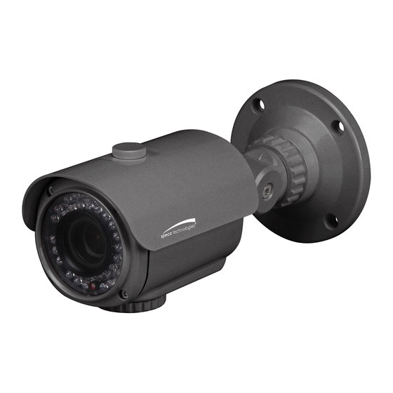
- Page 1 INSTRUCTION MANUAL Intense-IR Series 1000TVL HT7040K/HT7042K (Outdoor IR Bullet Camera) HT6040K (Outdoor IR Turret Camera) HT5940K (Outdoor IR Dome Camera) VL7038K (Outdoor IR Bullet Camera) HT649K (Indoor IR Dome Camera)
-
Page 2: Table Of Contents
Contents Contents ............1 Precautions ..........2, 3 Safety Instructions ........4 Package Contents ........5 Camera Installation ........6-12 Lens Adjustment ......... 13-16 ..........17-20 Camera Dimension ........21-22 Features ............23 OSD Menu Details ........24- 46 Trouble Shooting ......... 47... -
Page 3: Precautions
Precautions Do not install the camera in Do not install the camera under Do not touch the front lens of the extreme temperature conditions. unstable lighting conditions. camera. Only use the camera under conditions Severe lighting change or flicker can This is one of the most important parts of where temperatures are between cause the camera to work improperly. - Page 4 RISK OF ELECTRIC SHOCK DO NOT OPEN CAUTION:TO REDUCE THE RISK OF ELECTRIC SHOCK DO NOT REMOVE COVER(OR BACK). NO USER-SERVICEABLE PARTS INSIDE. REFER SERVICING TO QUALIFIED SERVICE PERSONNEL. ISO14001 The lightning flash with an arrowhead symbol, within an equilateral triangle is intended to alert the user to the presence of uninsulated dangerous voltage within the product's enclosure that may be of sufficient magnitude to constitute a risk of electric shock to persons.
-
Page 5: Safety Instructions
Safety Instructions There are no user serviceable parts inside Do not disassemble this camera other than to make initial adjustments Use a UL approved regulated 24 volt AC or 12 volt DC power supply Please insure that your installation area can support the weight of the camera Do not use a strong or abrasive detergent when cleaning the camera Do not install near cooling or heating device... -
Page 6: Package Contents
Package Contents Please make sure that the following items are included in the Package: 1) HT7040K, HT7042K 1 Video Test Connector, ower ack 1 ocus djustment 1 Bracket Base 1 rench et crew 4 Tapping crews 4x25 4 Hexagon ocket crews 5x10 2) HT6040K 1 Video Test Connector, ower ack 2 renches... -
Page 7: Camera Installation
CAMERA INSTALLATION... - Page 8 CAMERA INSTALLATION Compatibility 1) HT7040K, HT7042K CVCJBB INTJBS INTCM 2) HT6040K CVCJBD Adaptor plate(60PLATE) with rubber...
- Page 9 CAMERA INSTALLATION Compatibility 3) HT5940K CVCJBD Adaptor plate(59PLATE) with rubber 4) VL7038K INTJBS INTCM...
- Page 10 CAMERA INSTALLATION Compatibility 5) HT649K INTWM CVCJBD INTCM INTPM...
- Page 11 The installation instructions in this manual are for use by ualified ser ice personnel only. To reduce the risk of electric shock, do not perform any ser icing other than that contained in the operating instructions unless you are qualified to do so. CAMERA INSTALLATION 1.
- Page 12 CAMERA INSTALLATION 2. HT6040K BALL DOME BASE SCREW TS T1, 4X25, TH, SUS, 3EA BALL DOME BALL DOME BODY...
- Page 13 CAMERA INSTALLATION 3. HT5940K VANDAL DOME BASE SCREW TS T1, 3.5X20, PH, SUS, 3EA VANDAL DOME BODY BODY OUTER COVER SPECO...
- Page 14 CAMERA INSTALLATION 4. VL7038K WALL BRACKET BASE CAMERA ASSEMBLY TAPPING SCREW 4X25, 4EA HEXAGON SOCKET SCREW M5X15, 4EA...
- Page 15 CAMERA INSTALLATION 5. HT649K BASE ASSEMBLY TAPPING SCREW 4X25, 3EA DOME COVER ASSEMBLY...
-
Page 16: Lens Adjustment
LENS ADJUSTMENT 1. HT7040K, HT7042K Open the cap Focus adjustment Lock screw Zoom adjustment... -
Page 17: Lens Adjustment
LENS ADJUSTMENT 2. HT6040K Zoom adjustment Lock screw Focus adjustment... - Page 18 LENS ADJUSTMENT 3. HT5940K Open the cap Focus adjustment Zoom adjustment...
- Page 19 LENS ADJUSTMENT 4. VL7038K...
- Page 20 LENS ADJUSTMENT 5. HT649K Open the cap Zoom adjustment Focus adjustment...
-
Page 21: Specifications
Intense-IR Series 1000TVL DC uto Iris Varifocal Lens 2.8 12mm / 5 50mm SPECIFICATIONS HT7040K / HT7042K Image Sensor 1/3" 1.3MP SONY Sensor Resolution 1000TV Lines Effective Pixels 1305(H) X 1049(V), 1.37M Pixels Total Pixels 1312(H) X 1069(V), 1.40M Pixels... - Page 22 Intense-IR Series 1000TVL DC uto Iris Varifocal Lens 2.8 12mm SPECIFICATIONS HT6040K Image Sensor 1/3" 1.3MP SONY Sensor Resolution 1000TV Line s E ective Pixels 1305(H) X 1049(V) , 1.37M Pixel s Total Pixels 1312(H) X 1069(V) , 1.40M Pixel s...
- Page 23 Intense-IR Series 1000TVL DC uto Iris Varifocal Lens 2.8 12mm SPECIFICATIONS HT5940K Image Sensor 1/3" 1.3MP SONY Sensor Resolution 1000TV Line s E ective Pixels 1305(H) X 1049(V) , 1.37M Pixel s Total Pixels 1312(H) X 1069(V) , 1.40M Pixel s...
- Page 24 Intense-IR Series 1000TVL DC uto Iris Varifocal Lens 2.8 12mm SPECIFICATIONS VL7038K Image Sensor 1/3" 1.3MP SONY Sensor Resolution 1000TV Lines Effective Pixels 1305(H) X 1049(V), 1.37M Pixels Total Pixels 1312(H) X 1069(V), 1.40M Pixels Scanning System Progressive Scan S/N Ratio...
- Page 25 Intense-IR Series 1000TVL DC uto Iris Varifocal Lens 2.8 12mm SPECIFICATIONS HT649K Image Sensor 1/3" 1.3MP SONY Sensor Resolution 1000TV Lines Effective Pixels 1305(H) X 1049(V), 1.37M Pixels Total Pixels 1312(H) X 1069(V), 1.40M Pixels Scanning System Progressive Scan S/N Ratio...
-
Page 26: Camera Dimension
CAMERA DIMENSION 1) HT7040K, HT7042K 8.27” 3.94” dia 4.80” 3.38” 2.95” 2) HT6040K 4.65” dia... - Page 27 CAMERA DIMENSION 3) HT5940K 3.23” dia 4) VL7038K 11.57” 5.31” 5.99” 4.76” 11.26”...
- Page 28 CAMERA DIMENSION 5) HT649K 3.94”dia 5.12”dia...
-
Page 29: Features
General Features 1000 TV Lines LO 1000 TVL combined with O OR (I 138) DR ( ide Dynamic Range) powerful and ultra ad anced technology that captures cleaner and superior high resolution picture e en where images appear dark because there is a strong back light present. reset (Indoor, Outdoor, Low light, Hallway, Lobby, le ator) is pro ided to maximi e user con enience. -
Page 30: How To Set Up The Camera Menu
How to Set Up the camera menu Setup Menu PRESET MODE MENU * ixed board lens type camera is a ailable for L option in L menu only. MAIN SETUP INDOOR OUTDOOR LOW LIGHT HALL WAY LOBBY ELEVATOR LENS MODE INDOOR / OUTDOOR / DEBLUR RETURN MANUAL... - Page 31 How to Set Up the camera menu Setup Menu SHARPNESS 0 ~ 10 GAMMA 0.45 ~ 0.65 IMAGE PEDSTAL 0 ~ 20 COLOR GAIN 0 ~ 20 MIRROR OFF / ON FLIP OFF / ON RETURN VIEW ANGLE WIDE 4 : 3 WIDE 16 : 9 XY ADJUST SYSTEM...
- Page 32 How to Set Up the camera menu Setup Menu ALARM ANTI-SHIFT OFF / ON SHIFT SCALE 0 ~20 ANTI-BLOCK OFF / ON BLOCK SCALE 0 ~ 20 RETURN QUICK ZOOM MOVING 0 ~ 240 sec ZOOM IN 0 ~ 240 sec STANDBY 0 ~ 240 sec SYNCHRONOUS...
- Page 33 1. ress the set button. will be displayed on the monitor. reset is pro ided to maximi e user con enience. T Indoor // Outdoor // Low light // Hallway // Lobby // le ator ) SPECO TECH 1. PRESET INDOOR 2. MAIN SETUP 3.
-
Page 34: Menu Setup
1. ress the set button. * The et p menu will be displayed on the monitor. MENU 1. LENS 2. EXPOSURE 3. WHITE BAL 4. BACKLIGHT 5. SPECO DNR MIDDLE 6. DAY&NIGHT AUTO 7. IMAGE 8. SYSTEM 9. SPECIAL RETURN 2. - Page 35 MENU 1. LENS 1. LENS MANUAL 2. EXPOSURE 2. EXPOSURE 3. WHITE BAL 3. WHITE BAL 4. BACKLIGHT 4. BACKLIGHT 5. SPECO DNR MIDDLE 5. SPECO DNR MIDDLE 6. DAY&NIGHT AUTO 6. DAY&NIGHT AUTO 7. IMAGE 7. IMAGE 8. SYSTEM 8.
- Page 36 Down button 2. elect the desired mode using the Left or Right buttons. MENU 1. LENS 2. EXPOSURE 3. WHITE BAL 4. BACKLIGHT 5. SPECO DNR MIDDLE 6. DAY&NIGHT AUTO 7. IMAGE 8. SYSTEM 9. SPECIAL...
- Page 37 H TT R sers adjust electronic shutter speed by selecting one of modes( L, LICK R). 2. EXPOSURE BRIGHTNESS IIIIIIIIII IIIIIIIIII SHUTTER MANUAL INTENSIFY IIIIIIIIII IIIIIIIIII RETURN anaul mode shutter speed is adjustable from 1/60 up to 1/60,000. SHUTTER SPEED 1/60 RETURN The brighter image can be displayed by operating digital slow shutter speed in low light en ironment.
-
Page 38: White Balance
Down button. 2. elect the desired mode by using the left or Right button. MENU 1. LENS 2. EXPOSURE 3. WHITE BAL 4. BACKLIGHT 5. SPECO DNR MIDDLE 6. DAY&NIGHT AUTO 7. IMAGE 8. SYSTEM 9. SPECIAL RETURN se the appropriate mode according to your purposes among these three modes. -
Page 39: Back Light
Down button 2. elect the desired mode using the Left or Right buttons. MENU 1. LENS 2. EXPOSURE 3. WHITE BAL 4. BACKLIGHT 5. SPECO DNR MIDDLE 6. DAY&NIGHT AUTO 7. IMAGE 8. SYSTEM 9. SPECIAL... - Page 40 HLC (Highlight Light Compensation) hen there is a car head light turned on at the entrance of the gas station or in some place in the parking lot, the numbers of the car plate can be recogni ed by blocking only the light from the car headlight. t the area is set up specifically, you can recogni e the car plate numbers by blocking the strong light signal.
- Page 41 ( To adjust DR le el, select the LO , IDDL , HI H by pressing the left or the right button ) WEIGHT HIGH RETURN WDR OFF WDR ON...
- Page 42 2. elect one of modes(O , LO , IDDL , HI H) to use D R by pressing the Right or Left button. MENU 1. LENS 2. EXPOSURE 3. WHITE BAL 4. BACKLIGHT 5. SPECO DNR MIDDLE 6. DAY&NIGHT AUTO 7. IMAGE 8. SYSTEM 9.
- Page 43 2. elect one of modes ( T R , TO, COLOR, B/ ) using the Left or Right buttons. MENU 1. LENS 2. EXPOSURE 3. WHITE BAL 4. BACKLIGHT 5. SPECO DNR MIDDLE 6. DAY&NIGHT AUTO 7. IMAGE 8. SYSTEM 9. SPECIAL RETURN T it can change into COLOR or B/ mode automatically through the connection with the ground terminal.
- Page 44 Down button. 2. elect one of the mode using the Left or Right buttons. MENU 1. LENS 2. EXPOSURE 3. WHITE BAL 4. BACKLIGHT 5. SPECO DNR MIDDLE 6. DAY&NIGHT AUTO 7. IMAGE 8. SYSTEM 9. SPECIAL RETURN 7.
- Page 45 the outline of an image becomes sharp and more distinct as the le el of sharpness increases. It has better be used to adjust the alue to the proper one depending on a sort of image. ( H R 10 ) amma alue is adjustable ( 0.45 0.65 )
- Page 46 Down button. 2. elect one of the mode using the Left or Right buttons. MENU 1. LENS 2. EXPOSURE 3. WHITE BAL 4. BACKLIGHT 5. SPECO DNR MIDDLE 6. DAY&NIGHT AUTO 7. IMAGE 8. SYSTEM 9. SPECIAL RETURN 8.
- Page 47 2. elect one of the mode using the Left or Right buttons. SPECIAL MENU 1. LENS D-ZOOM 1. 0X 2. EXPOSURE D-WDR 3. WHITE BAL DEFOG 4. BACKLIGHT SHADING 5. SPECO DNR MIDDLE PRIVACY 6. DAY&NIGHT AUTO INTELLIGENT 7. IMAGE RETURN 8. SYSTEM 9. SPECIAL RETURN...
- Page 48 CI L D OO diginal oom supports up to x8 a ailable (x1 The higher the digital oom magnification is, the lower the resolution is. DR This camera which is using 3D D R D pro ides intelligent light le el control to o ercome e en strong backlight conditions.
- Page 49 H DI It is used to increase brightness in case angle of lens set as wide cause darker image on both sides than that on the center. SHADING WEIGHT 100% RETURN RIV C This is used to hide certain areas on the monitor. ou can designate each different 15 area. The si e of a designated area can be adjusted.
- Page 50 MTN TRACKER DET. SETTING WINDOW TONE WINDOW ZONE WINDOW USE DET H-POS DET V-POS DET H-SIZE DET V-SIZE RETURN 2) L R it is used to set TI HI T or TI BLOCK based on motion tracking. scale le el of these functions are adjustable ALARM ANTI-SHIFT SHIFT SCALE...
- Page 51 TI BLOCK If someone intentionally block the front of camera by hands or spray, etc., it will be automatically detected by a warning message(BLOCKI D T CT D on monitor. ICK OO Digital oom in is operated to precisely detect objects when objects get in a designated motion detection area.
- Page 52 10. RETURN MENU 1. LENS 2. EXPOSURE 3. WHITE BAL 4. BACKLIGHT 5. SPECO DNR MIDDLE 6. DAY&NIGHT AUTO 7. IMAGE 8. SYSTEM 9. SPECIAL RETURN ress R T R button to sa e the current settings and exit the setup menu.
-
Page 53: Trouble Shooting
Trouble Shooting PROBLEM POSSIBLE CAUSE Check the power cable, power supply output and video Northing appears on connection between the camera and monitor. the screen. Are the camera lens or the lens glass dirty? Clean the lens / glass with a soft clean cloth. The image on the Adjust the monitor controls, as required. - Page 55 MEMO...
- Page 56 MEMO...
- Page 57 MEMO...
- Page 58 200 New Highway Amityville, NY 11701 631-957-8700 1 800 645 5516 www.specotech.com...
Need help?
Do you have a question about the Intense-IR Series and is the answer not in the manual?
Questions and answers