Advertisement
Table of Contents
Advertisement
Table of Contents

Subscribe to Our Youtube Channel
Related Manuals for Speco VLBT5W


Summary of Contents for Speco VLBT5W
-
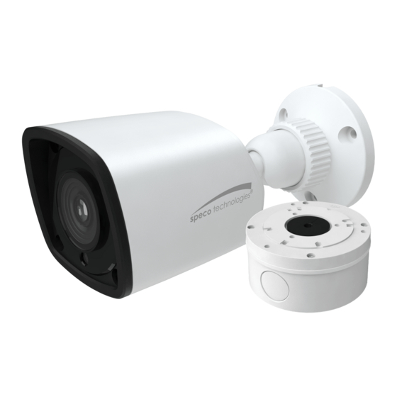
Page 1: User Manual
VLBT5W /VLBT6W/ VLDT5W/VLDT6M/VLT7W User Manual Thank you for purchasing our product. Speco Technologies is constantly developing and improving products. We reserve the right to modify product design and specifications without notice and without incurring any obligation. - Page 2 ■ If the product does not work properly, please contact the dealer or where the product was purchased. Speco Technologies is not responsible for any problems caused by improper operation or repair. ■ Keep away from liquid while in use.
-
Page 3: Installation
You’d better install back the lens cover or lower dome less than 4 hours after removing it. The mounting types of cameras are only for reference. ►Mounting for VLBT5W/VLBT6W 1. Drill the screw holes and the cable hole on the wall according to the drill template. - Page 4 2. Route and connect the cables . 3. Secure the mounting base with camera to the wall with screws as shown below. 4. Bracket adjustment. Before adjustment, preview the image of the camera on a monitor and then loosen the fixed ring to adjust the view angle of the camera.
- Page 5 88 mm ∅6 ∅148 ∅22 89mm Lock Screw Lower Dome Route and connect the cables. And then secure the mounting base to the ceiling or wall with the screws provided. Sponge Mounting Base 4. Fix the camera to the mounting base with the lock screw. 5.
-
Page 6: Lower Dome
7. Install the lower dome back to the camera with the screws and remove the protection film s oftly to complete the ins tallation. ● Mounting for VLDT5W 1. Drill the screw holes and the cable hole on the wall according to the drill template. 2. - Page 7 Three-axis adjustment. Before adjustment, preview the image of the camera on a monitor and then adjust the camera according to the figure below to get an optimum angle. 6. Install the lower dome back to the camera and secure it with the screws. Pan 0°~355°...
-
Page 8: Specifications
Specifications Models VLBT5W VLBT6W VLDT6M VLD T5W VLT7W Specifications Camera Image Sensor 1/2.8" COMS Resolution Image size 1920×1080 Video Output AHD/TVI/CVI/CVBS (*camera comes defaulted to HD-TVI) Image System PAL/NTSC Electronic Shutter Auto; 1/50s~1/100000s(PAL);1/60s~1/100000s (NTSC) IR Distance (feet) 32.8~65.6 65.6 ~98.4 65.6~98.4...
Need help?
Do you have a question about the VLBT5W and is the answer not in the manual?
Questions and answers