Buderus Logano G315 Installation And Service Instructions Manual
Low-temperature oil/gas boiler
Hide thumbs
Also See for Logano G315:
- Assembly, maintenance and operating instruction (30 pages) ,
- Operating instructions manual (8 pages) ,
- Installation and service instructions manual (56 pages)
Table of Contents
Advertisement
Installation and
Service Instructions
Logano G315
Boilers for oil/gas-fired power burners
Low-temperature
oil/gas boiler
WARNING: If installation, adjustment, modification, oper-
ation or maintenance of the heating system is carried out
by an unqualified person, this may result in personal injury
or property damage.
The directions of this installation manual must be followed
precisely.
If support or additional information is required, contact a
qualified service company, service provider or the gas
company.
WARNING:
Observe the safety instructions of this installation manual
before placing the heating appliance in operation.
The operating manual is a component of the technical
documentation and must be handed over to the operator
of the heating system. Explain to the owner or operator
how to use the heating system using the operating
instructions. Make sure that he has been familiarized with
all information required for the operation of the heating
system.
NOTICE: If the heating appliance will be installed in Mas-
sachusetts, it must be installed by an installer or dealer
who is registered there.
This manual is available in the English and French
language.
Please keep this manual for future reference.
For contractors
Read carefully prior to
installation and maintenance
Advertisement
Table of Contents

Related Manuals for Buderus Logano G315


Summary of Contents for Buderus Logano G315
- Page 1 This manual is available in the English and French language. Please keep this manual for future reference. Logano G315 For contractors Read carefully prior to Boilers for oil/gas-fired power burners installation and maintenance...
-
Page 2: Table Of Contents
The oil/gas-fired boiler Logano G315 is available in two Specifications ......11 variants (disassembled and assembled). - Page 3 ......45 13.7 Inspection and maintenance reports ..46 Logano G315 - Subject to technical modifications...
-
Page 4: Guideline To Symbols And Safety Instructions
Listing/list entry open B Always de-energize the connection before working on – Listing/list entry (2nd level) electrical parts (circuit breaker). Take measures to Tab. 1 prevent accidental reconnection. B Take provisions against unintentional reconnection. Logano G315 - Subject to technical modifications... - Page 5 B Inform the customer that they must not carry out any modifications or repairs. B Only use the boiler for its intended purpose and only when it is in working order. Logano G315 - Subject to technical modifications...
-
Page 6: Product Description
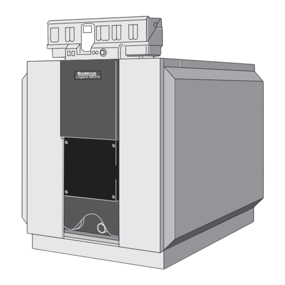
Particular emphasis is placed on ease of operation. Please observe the safety instructions and the operating instructions to ensure optimum safe, economical and environmentally-friendly utilization of your system. The main components of the Logano G315 oil/gas-fired boiler are: • Boiler block ( Fig. 1, [3]) 6 720 642 622-01.1o... -
Page 7: Designated Use
Natural Gas (NG) Remarks The Logano G315 boiler can be operated with the specified fuels. Select a burner suitable for use with the fuels specified for the Logano G315 boiler. The output figures shown in the Table “Technical Data” are nominal power figures. -
Page 8: Operating Conditions
This shunt pump circuit can be controlled either with a Buderus 4000 control panel or with a third- This operating condition can be easily achieved by the party controller. Failure to ensure that the operating... -
Page 9: Compliance With Standards And Regulations
Valves external to the boiler must be fitted with T-handles and condensate piping must be installed in accordance with the State Plumbing Code. Logano G315 - Subject to technical modifications... -
Page 10: Additional Regulations For Installations In The Commonwealth Of Massachusetts
The sign shall read, in print size no less than appliance or equipment at the completion of the one-half (½) inch in size, “GAS VENT DIRECTLY installation. BELOW. KEEP CLEAR OF ALL OBSTRUCTIONS”. Logano G315 - Subject to technical modifications... -
Page 11: Specifications
(155 mm) 7" (180 mm) 6 720 642 621-48.1o Fig. 3 Technical data for Logano G315 (dimensions in inches (mm)) Drain valve (Rp ¾) Boiler heat exchanger length Overall boiler length Return connection on the boiler Supply connection on the boiler 1) With the drain valve (EL), you may only drain the system, not fill it. - Page 12 45.25 52.5 67.5 Gas capacity gal. 38.83 47.82 56.8 65.78 69.48 Flue gas temperature, °F 178.6 280.4 176.8 269.6 285.8 partial load (60 %) ( °C) (137) (138) (136) (132) (141) Tab. 4 Logano G315 - Subject to technical modifications...
- Page 13 3) Safety limit (high limit safety cut-out). Maximum possible supply temperature = safety limit (STB) – 32 °F ( – 18 K). Example: Safety limit (STB) = 212 °F (100 °C), max. possible supply temperature = 212 – 32 = 180 °F (100 – 18 = 82 °C). Logano G315 - Subject to technical modifications...
-
Page 14: Scope Of Delivery
Scope of delivery Scope of delivery Transporting the boiler The Logano G315 can be delivered either as a pre- Use suitable equipment to transport the individual boiler assembled block or in loose sections. sections (delivery unassembled) and other individual parts. -
Page 15: Positioning The Boiler
• Blanking flange with vent facility (for pressure test) sections boiler hub boiler hub (mm) 121-1/4 5 – 9 (3080 mm) Tab. 7 For the correct arrangement of the flange when performing the assembly procedure, refer to page 22. Logano G315 - Subject to technical modifications... -
Page 16: Recommended Wall Clearances
(AB). A distance of AB +4 inches (AB + 100 mm) from the wall is recommended. The length L depends on the number of boiler sections or boiler rating Spare parts, page 51. Logano G315 - Subject to technical modifications... -
Page 17: Installing The Boiler On A Boiler Base Or Foundation
(100 x 5 mm) steel flat should be incorporated ( Fig. 6 and Tab. 9). 34-3/4" 34 3/4" (~ 880 mm) 4" (100 mm) 21 1/4" (540 mm) 6 720 642 621-01.1o Fig. 6 Base dimensions Logano G315 - Subject to technical modifications... -
Page 18: Boiler Block Assembly
For details of assembling the remainder of the boiler if the heat exchanger is delivered pre- assembled, see Chapter 7.3, page 23. Logano G315 - Subject to technical modifications... -
Page 19: Joining The Boiler Block Assembly
B Ensure adequate ventilation of the installation area. B Please note the handling and safety instructions of the product used. Fig. 11 Driving nipples home Logano G315 - Subject to technical modifications... - Page 20 To make installation easier, place the boiler section to be fitted onto the nipple on the upper hub first. Once this has been done, the boiler section can be aligned with the lower hub. Fig. 13 Inserting sealant rope Logano G315 - Subject to technical modifications...
- Page 21 B Only boiler assembly tools size 2.3 may be B Never compress more than one nipple used (Fig. 4, page 15 and Fig. 17, [1 and 2]). joint at a time. B Stop compressing the sections when the boiler hubs meet. Logano G315 - Subject to technical modifications...
- Page 22 B Now tighten the nuts on the tie rods 1 to 1½ turns. B Level the boiler block vertically and horizontally on the base/foundation ( Chapter 6.3, page 17). B Remove boiler assembly tool. Fig. 18 Boiler assembly tool on rear section Logano G315 - Subject to technical modifications...
-
Page 23: Setting Up The Boiler Block
Chapter 6.3, page 17). The following pages describe the installation of the supply pipe and sensor well. You must do both irrespective of whether the boiler is supplied pre-assembled or in separate sections. Logano G315 - Subject to technical modifications... -
Page 24: Sliding The Supply Pipe Into Place
( Fig. 21, [3]) fits in the notch in the top boiler hub Fig. 21, [5]) (Thermostream principle). Fig. 22 Fitting the sensor well Fig. 21 Installing the supply pipe Logano G315 - Subject to technical modifications... -
Page 25: Leak Test
Fig. 23 Fitting the flange B Slowly fill the boiler with water via the fill and drain connection. While doing this, purge the boiler via the boiler flow connection with purger. Logano G315 - Subject to technical modifications... -
Page 26: Supply Flange With Safety Components
B When the heating system is in operation, do not fill it via the boiler fill & drain valve. Instead, use the fill valve on the system side. Logano G315 - Subject to technical modifications... -
Page 27: Installing Fittings And Burner Door
B Place the draft diverter onto the two threaded studs on the rear section (Fig. 28, [4 and 5]) and secure using washers and nuts. Fig. 29 Rear section with fittings installed Fig. 28 Fitting the draft diverter Logano G315 - Subject to technical modifications... -
Page 28: Inserting The Flue Gas Baffle Plates
(mm) Fig. 30) Fig. 31 Hooking in the burner door 14-11/64 (360) top right 17-21/64 6 – 7 top left (440) bottom right 14-11/64 bottom left (360) 7-7/8 (200) Tab. 10 Logano G315 - Subject to technical modifications... -
Page 29: Boiler Outer Casing
(M 8 x × 15). The folded edge of the upper crosswise tier bar must point towards the front. 6 720 642 621-28.1o Fig. 34 Thermal insulation Rear (boiler back) Front (boiler front) Logano G315 - Subject to technical modifications... - Page 30 (Fig. 35, [1]). B Close the slot below the flue outlet with spring hooks (Fig. 35, [3]). Fig. 36 Fitting the front thermal insulation Fig. 35 Fitting the rear section thermal insulation Logano G315 - Subject to technical modifications...
-
Page 31: Fitting Side Panels And Top Covers
(Fig. 38, [2]). one self-tapping screw in each case (Fig. 40, [1 and 3]). Fig. 38 Fitting the front cover Fig. 40 Fitting the front base rail Logano G315 - Subject to technical modifications... - Page 32 (Fig. 42, [1 and 3]). B Hook burner door panel into the cut-outs in the front cover (Fig. 44, [3]). Fig. 42 Fitting the bottom rear boiler panel Fig. 44 Attaching the burner door panel Logano G315 - Subject to technical modifications...
-
Page 33: Installing A Vent Pipe Sealing Collar
Fig. 45 Installing the vent pipe Vent pipe sealing collar Flue gas temperature sensor Sleeve Vent pipe hose clamps Exhaust Manifold 2 × Vent pipe diameter, at least 28 22/64 inches (720 mm) Logano G315 - Subject to technical modifications... -
Page 34: Installing The Control Panel
Chapter 7.5, page 24). The temperature sensor set connected to the control panel (consisting of three temperature sensors and one sensor blind piece Fig. 48, [1]) is installed in the sensor well R¾ ". Logano G315 - Subject to technical modifications... - Page 35 Fig. 49 Making the electrical connections B Wire up the electrical connections as shown in the wiring diagram. Take care to ensure correct cable and capillary tube routing. Fig. 51 Boiler with fitted control panel Logano G315 - Subject to technical modifications...
-
Page 36: Mounting The Burner
( Fig. 52, [4]) using the appropriate insulating rings ( Fig. 52, [3]). B Connect the vent connection to the burner to ensure the inspection window remains free of deposits. Logano G315 - Subject to technical modifications... -
Page 37: System Start-Up
System start-up 11 System start-up You can connect control panels of the 4000 series to the Logano G315. The commissioning process for the different types of control panel is the same. NOTICE: The boiler can be damaged through heavy dust deposits! B Do not operate the boiler where heavy dust contamination persists, e.g. -
Page 38: Commissioning The System
If you notice when taking measurements for the commissioning log that the flue gas temperature is too low for the vent pipe (risk of condensation), you can raise the flue gas temperature ( Chapter 11.5, page 38). Logano G315 - Subject to technical modifications... -
Page 39: Commissioning Log
System start-up 11.6 Commissioning log B Sign all start-up work as completed and enter the The Logano G315 can be used with an oil- or gas-fired burner. Fill in the commissioning log for the appropriate relevant date. type of oil or gas burner carefully. -
Page 40: Shutting Down The System
Shutting down the system 12 Shutting down the system You can connect control panels of the 4000 series to the Logano G315. The shutting down process for the different types of control panel is the same. NOTICE: Risk of system damage from freezing. -
Page 41: System Inspection And Maintenance
Fig. 55 Removing the front panel unintentional reconnection. B Swing out burner door. B Take the flue gas baffle plates forwards out of the flue gas passages (Fig. 56, [1 – 4]). Logano G315 - Subject to technical modifications... - Page 42 Fig. 56 Flue gas baffles, removing Fig. 58 Heat exchanger heater flue, cleaning B Undo the four self-tapping screws on the rear boiler The various brush types available from Buderus (optional extras) are shown in Fig. 57. panel at the bottom.
-
Page 43: Wet-Cleaning The Boiler
B Spray cleaning agent evenly from the top into the flue gas passages. B Heat up the boiler to a boiler water temperature of at least 158 °F (70 °C). B Brush out the heat exchanger heater. Logano G315 - Subject to technical modifications... -
Page 44: Checking The Operating Pressure
B Read the current operating pressure (psi) and temperature °F (°C) from the temperature/pressure gauge. B If the operating pressure drops below 15 psi (1 bar), refill boiler water. 7 747 019 141-17.1RS Fig. 61 Pressure/temperature gauge Logano G315 - Subject to technical modifications... -
Page 45: Refilling With Boiler Water And Purging
B Ensure that your heating system is bled. B Check the heating system for leaks and the function of the expansion vessel. Logano G315 - Subject to technical modifications... -
Page 46: Inspection And Maintenance Reports
If during inspection work conditions are identified that require maintenance, this work must be performed on an as-required basis. If make-up water is added, the quality of this water must correspond to the specifications in the enclosed operating manual. Logano G315 - Subject to technical modifications... - Page 47 System inspection and maintenance Date:____________ Date:____________ Date:____________ Date:____________ Company stamp/ Company stamp/ Company stamp/ Company stamp/ signature signature signature signature Logano G315 - Subject to technical modifications...
- Page 48 (see burner documentation) Commissioning the heating system Record the final checks of the maintenance work, incl. measurements and test results Check safe and proper operation Confirm professional inspection Company stamp/ Company stamp/ signature signature Logano G315 - Subject to technical modifications...
- Page 49 System inspection and maintenance Date:____________ Date:____________ Date:____________ Date:____________ Company stamp/ Company stamp/ Company stamp/ Company stamp/ signature signature signature signature Logano G315 - Subject to technical modifications...
-
Page 50: Troubleshooting Burner Faults
If the burner does not restart after three attempts, refer to the technical documentation provided with the burner to find out how to reset it. Logano G315 - Subject to technical modifications... -
Page 51: Spare Parts
Group 2 – boiler block - draft diverter page 52 Group 3 – burner door G315 page 57 Group 4 – burner door G315 VM page 59 Group 5 – jacket page 61 Tab. 13 Spare part groups Logano G315 Logano G315 - Subject to technical modifications... - Page 52 Spare parts 6720906566.aa.RS-Kesselblock G315 Fig. 63 Group 1 – boiler block - front Logano G315 Logano G315 - Subject to technical modifications...
- Page 53 63 019 498 Supply pipe 9 pcs. compl G315 VM 63 019 639 Supply pipe - studs VM 8 718 571 352 0 Tab. 14 Group 1 – boiler block - front Logano G315 Logano G315 - Subject to technical modifications...
- Page 54 Fittings G315 9-pc loose spare Primer 181, 12.5 oz (370 ml) in 17 oz (500 ml) can Sealant graphite treated with linseed oil 450 g can Tab. 14 Group 1 – boiler block - front Logano G315 Logano G315 - Subject to technical modifications...
- Page 55 Spare parts 6720906567.aa.RS-Kesselblock-Anbauteile G315 Fig. 64 Group 2 – boiler block - draft diverter Logano G315 Logano G315 - Subject to technical modifications...
- Page 56 5 371 906 Sealant rope GP10x1070 mm long 63 020 962 Sealing compound brown 63 014 361 Maintenance package G315 63 006 595 Tab. 15 Group 2 – boiler block - draft diverter Logano G315 Logano G315 - Subject to technical modifications...
- Page 57 Spare parts M10x25 M12x35 6720906568.aa.RS-Brennertür G315 Fig. 65 Group 3 – burner door Logano G315 Logano G315 - Subject to technical modifications...
- Page 58 Hex-head bolt ISO4017 M12x45 (10x) 8 718 575 468 0 Sealing compound brown 63 014 361 Ramming mass JM 500/G 3.5 kg 63 001 856 Tab. 16 Group 3 – burner door Logano G315 Logano G315 - Subject to technical modifications...
- Page 59 Spare parts M12x35 6720906569.aa.RS-Brennertür VM-Brenner G315 Fig. 66 Group 4 – burner door Logano G315 VM Logano G315 - Subject to technical modifications...
- Page 60 8 718 575 468 0 Washer DIN9021 A6,4 A3K 5 264 166 Sealing compound brown 63 014 361 Ramming mass JM 500/G 3.5 kg 63 001 856 Tab. 17 Group 4 – burner door Logano G315 VM Logano G315 - Subject to technical modifications...
- Page 61 Spare parts 6720906570.aa.RS-Verkleidung G315 Fig. 67 Group 5 – jacket Logano G315 Logano G315 - Subject to technical modifications...
- Page 62 Mounting material for jacket G315 5 614 740 Burner hood G315 VM 63 020 282 Cover Br-H G315 VM 63 020 283 Logano G315 name plate 67 902 826 Tab. 18 Group 5 – jacket Logano G315 Logano G315 - Subject to technical modifications...
- Page 63 Spare parts M16x65 G1/4" G1" 27,5x17 G1/4"xG1/4" 6720906573.aa.RS-Sicherheits-Set G315 Fig. 68 Group 8 – safety group Logano G315 Logano G315 - Subject to technical modifications...
- Page 64 8 718 571 894 0 Double nipple G1" 104 lg 5 681 062 Gasket set KSG 5 639 634 Gasket set O-ring V1 5 354 969 Tab. 19 Group 8 – safety group Logano G315 Logano G315 - Subject to technical modifications...
-
Page 65: Index
Boiler conditions of use ............Control Panel Assembly ............Fill water .................. Flow temperature ..............Fuels................... Operating pressure, maximum ..........Product description ..............Safety instructions ..............Temperature control ............... Thermal insulation ..............Transport ................. Logano G315 - Subject to technical modifications... -
Page 66: Appendix
______________________ Manufacturer no. ______________________ Location ______________________ The technical documentation has been handed over to the user. He has been familiarized with the safety instructions, operation and maintenance of the system. Date, signature (user) Logano G315 - Subject to technical modifications... - Page 67 Appendix Logano G315 - Subject to technical modifications...
- Page 68 United States and Canada Bosch Thermotechnology Corp. 50 Wentworth Avenue Londonderry, NH 03053 Tel. 603-552-1100 Fax 603-584-1681 www.buderus.us U.S.A. Products manufactured by Bosch Thermotechnik GmbH Sophienstrasse 30-32 D-35576 Wetzlar www.buderus.com Bosch Thermotechnology Corp. reserves the right to make changes without notice due to continuing...
Need help?
Do you have a question about the Logano G315 and is the answer not in the manual?
Questions and answers