
Subscribe to Our Youtube Channel
Related Manuals for Kramer VA-1USB-T


Summary of Contents for Kramer VA-1USB-T
- Page 1 K R A ME R E LE CT R O N IC S L TD . USER MANUAL MODELS: VA-1USB-T USB Transmitter VA-1USB-R USB Receiver P/N: 2900-300209 Rev 3...
-
Page 3: Table Of Contents
Safety Instructions Recycling Kramer Products Shielded Twisted Pair/Unshielded Twisted Pair Overview Defining the VA-1USB-T and VA-1USB-R USB Transmitter and Receiver Defining the VA-1USB-T USB Transmitter Defining the VA-1USB-R USB Receiver Connecting the VA-1USB-T and VA-1USB-R Connecting to the product via RS-232... -
Page 4: Introduction
Introduction Welcome to Kramer Electronics! Since 1981, Kramer Electronics has been providing a world of unique, creative, and affordable solutions to the vast range of problems that confront video, audio, presentation, and broadcasting professionals on a daily basis. In recent years, we have redesigned and upgraded most of our... -
Page 5: Getting Started
Achieving the Best Performance To achieve the best performance: Use only good quality connection cables (we recommend Kramer high- performance, high-resolution cables) to avoid interference, deterioration in signal quality due to poor matching, and elevated noise levels (often associated with low quality cables) ... -
Page 6: Safety Instructions
There are different levels of STP cable available and we advise you to use the best quality STP cable that you can afford. For the VA-1USB-T and VA-1USB-R pair we recommend the use of shielded, twisted pair (STP), non-skew-free Kramer BC-STP cable. -
Page 7: Overview
USB, bidirectional RS-232 data and unidirectional IR signals over extended distances using CAT 5/6 cable. The VA-1USB-T encodes USB signals and RS-232 data and transmits them over CAT 5/6 cable as a TP signal. The VA-1USB-R decodes the signal from the TP into USB signals and RS-232 data. -
Page 8: Defining The Va-1Usb-T And Va-1Usb-Rusb Transmitter And Receiver
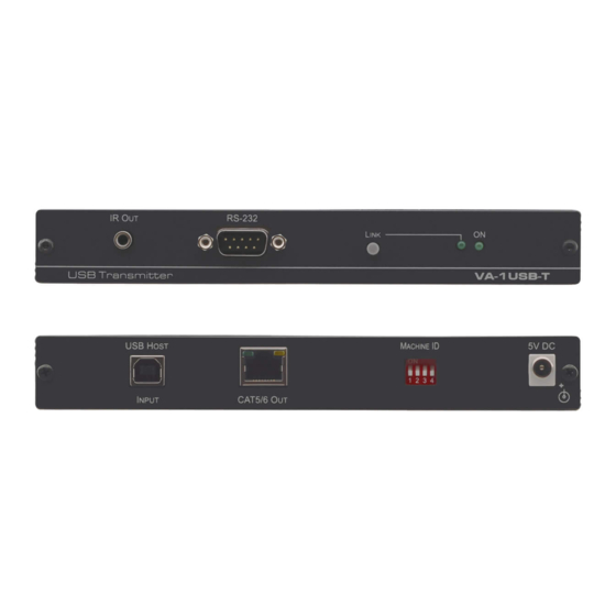
Press to reset the device to factory default (see Section 5.3) LINK LED Lights green when the TP link to the receiver is established ON LED Lights green when the device is powered on VA-1USB-T/VA-1USB-R - Defining the VA-1USB-T and VA-1USB-R USB Transmitter and Receiver... -
Page 9: Defining The Va-1Usb-R Usb Receiver
Defining the VA-1USB-R USB Receiver The VA-1USB-R decodes the USB signal and RS-232 data from the TP link sent from the VA-1USB-T. The receiver distributes the USB signal across four USB ports (acting as a USB hub) and outputs the RS-232 data. The VA-1USB-R receives an IR signal via its IR sensor and sends it over the TP link to the VA-1USB-T. -
Page 10: Figure 3: Va-1Usb-R Usb Receiver Front Panel
Use to set the device ID to pair with the transmitter (see DIP-switch Section 5.2) 5V DC Power Connector Connect to one of the supplied +5V DC power adapters. Center pin positive VA-1USB-T/VA-1USB-R - Defining the VA-1USB-T and VA-1USB-R USB Transmitter and Receiver... -
Page 11: Connecting The Va-1Usb-T And Va-1Usb-R
VA-1USB-T/VA-1USB-R. After connecting your VA-1USB-T/ VA-1USB-R, connect the power to the transmitter and receiver and then switch on the power to the other devices. Figure 5: Connecting the VA-1USB-T Transmitter and VA-1USB-R Receiver VA-1USB-T/VA-1USB-R - Connecting the VA-1USB-T and VA-1USB-R... - Page 12 DIP-switch (see Section 5.2). 5. Connect the power adapters to the power sockets on the VA-1USB-T and VA-1USB-R, and plug the adapters into the mains electricity (not shown in Figure 6. Establish a TP link by pressing the Link button on the receiver.
-
Page 13: Connecting To The Product Via Rs-232
RS-232 9-pin D-sub port on your PC Setting the Device ID DIP-switch The Device ID DIP-switch is used on both the VA-1USB-T transmitter and VA-1USB-R receiver to set matching device numbers. This allows up to 16 pairs of transmitters and receivers to communicate independently on the same TP subnet. -
Page 14: Resetting The Va-1Usb-T To Factory Default Settings
Device ID Resetting the VA-1USB-T to Factory Default Settings To reset the VA-1USB-T to factory default settings: 1. Turn off the power to the device. 2. Press and hold the Reset button while turning on the power to the device. -
Page 15: Using The Web Pages
2. Type the IP address (see Section 9) of the VA-1USB-T/VA-1USB-R in the address bar of your browser. (The IP address for the VA-1USB-T is shown, for the IP address of the VA-1USB-R see Section Figure 7: Entering the IP Address in your Browser... -
Page 16: The System Tab
9) you can: View the version information Update the firmware Run functions Figure 9: System Tab To update the firmware: 1. Click on Update Firmware. The window shown in Figure 10 is displayed. VA-1USB-T/VA-1USB-R - Using the Web Pages... -
Page 17: Figure 10: Update Firmware Window
7. When the process is complete, reboot the device (as indicated by the message shown in Figure 11) by clicking on Utilities and clicking Reboot. The device is rebooted with the new firmware. VA-1USB-T/VA-1USB-R - Using the Web Pages... -
Page 18: The Network Tab
2. Modify the IP address, subnet mask and default gateway addresses as required. 3. Click Apply. The changes are made and the message shown in Figure 13 is displayed. Figure 13: Warning Message VA-1USB-T/VA-1USB-R - Using the Web Pages... -
Page 19: The Functions Tab
3. Modify the serial communication parameters using the drop-down lists for Baud rate, Data bits, Parity and Stop bits. 4. Click Apply. The changes are made and the message shown in Figure 15 is displayed. VA-1USB-T/VA-1USB-R - Using the Web Pages... -
Page 20: Figure 15: Warning Message
Figure 15: Warning Message 5. Reboot the device by clicking on Utilities and clicking Reboot. The device is rebooted with the new IP parameters. VA-1USB-T/VA-1USB-R - Using the Web Pages... -
Page 21: Wiring The Twisted Pair Rj-45 Connectors
Wire Color Orange / White Orange Green / White Blue Blue / White Green Brown / White Brown Pair 1 4 and 5 Pair 2 1 and 2 Pair 3 3 and 6 VA-1USB-T/VA-1USB-R - Wiring the Twisted Pair RJ-45 Connectors... -
Page 22: Technical Specifications
TEMPERATURE: HUMIDITY: 10% to 90%, RHL non-condensing DIMENSIONS: 12.1cm x 7.18cm x 2.42cm (4.76" x 2.83" x 0.95"), W, D, H WEIGHT: 0.44kg (0.97lbs.) approx. each INCLUDED 2 Power supplies ACCESSORIES: RK-T2B 19” rack adapter OPTIONS: VA-1USB-T/VA-1USB-R - Technical Specifications... -
Page 23: Default Communication Parameters
Default Communication Parameters RS-232 VA-1USB-T VA-1USB-R Baud Rate: 115200 Data Bits: Stop Bits: Parity: None Ethernet IP Address: 192.168.1.39 192.168.1.40 Network Mask: 255.255.255.0 Default Gateway: 192.168.1.1 VA-1USB-T/VA-1USB-R - Default Communication Parameters... - Page 25 This page is intentionally left blank...
- Page 26 For the latest information on our products and a list of Kramer distributors, visit our Web site where updates to this user manual may be found. We welcome your questions, comments, and feedback. Web site: www.kramerelectronics.com E-mail: info@kramerel.com SAFETY WARNING...
Need help?
Do you have a question about the VA-1USB-T and is the answer not in the manual?
Questions and answers