Table of Contents
Advertisement
Advertisement
Table of Contents
Troubleshooting

Related Manuals for Stairmaster Stratus Systems


Summary of Contents for Stairmaster Stratus Systems
- Page 1 Stratus Systems Owner’s Manual...
- Page 2 Fax (425) 823-9490 www.stairmaster.com P/N 21442-H ©1997, 2000 StairMaster Health & Fitness Products™ and StairMaster are either a registered trademark or trademark of StairMaster Health & Fitness Products™ in the United States and/or other countries. StairMaster is a Rutledge Capital company.
- Page 3 This is to certify that the StairMaster Stratus systems cycle ergometer is warranted for a period of three years by StairMaster Health & Fitness Products™ to be free of all defects in materials and workmanship. This warranty does not apply to any defect caused by negligence, misuse, accident, alteration, improper maintenance, or an “act of God.”...
- Page 4 WHAT IS THE STAIRMASTER STRATUS CYCLE ERGOMETER? The Stratus systems cycle ergometers have 14 levels of intensity for the MANUAL program and 20 levels of intensity for the other programs. The Stratus uses a variable resistance system to maintain constant power within any given intensity level.
-
Page 5: Table Of Contents
CONTENTS SAFETY GUIDELINES ..................1 INTRODUCTION ....................3 INSTALLATION INSTRUCTIONS ..............5 BASIC OPERATING INSTRUCTIONS ............. 6 Adjustments ..................6 The ATTRACT Mode ................7 Basic Instructions For First-Time Users ..........7 GENERAL EXERCISE GUIDELINES ..............9 Setting a Goal ..................9 Flexibility Training ................. - Page 6 CONTENTS Initial Service ..................32 Preventive Maintenance ............... 32 TROUBLESHOOTING GUIDELINES ..............36 General Troubleshooting Guidelines ............. 36 Systematic Electrical Troubleshooting ..........36 Systematic Mechanical Troubleshooting..........38 Console Diagnostic Tests ..............40 PARTS REMOVAL AND REPLACEMENT ............44 Covers ....................44 Console ....................
- Page 7 Figure 1: Major Parts, 3300 CE ............. 3 Figure 2: Major Parts, 3900 RC ............. 4 Figure 3: End Caps ................5 Figure 4: Stratus Systems Console ............13 Figure 5: Fat Burner ................19 Figure 6: Fat Burner Plus ............... 20 Figure 7: Rolling Hills ................
-
Page 8: Safety Guidelines
SAFETY GUIDELINES HEN USING ELECTRICAL EQUIPMENT ALWAYS FOLLOW THESE BASIC PRECAUTIONS IMPORTANT SAFETY INSTRUCTIONS This symbol appearing throughout this manual means Attention! Be Alert! Your safety is involved. The following definitions apply to the words “Danger” and “Warning” found throughout this manual: DANGER - Used to call attention to IMMEDIATE hazards which, if not avoided, will result in immediate, serious personal injury or loss of life. - Page 9 Use this machine only for its intended use as described in this Manual. Do not use parts, attachments, or accessories other than those provided by StairMaster Health & Fitness Products™. Do not use the external power supply if it has a damaged cord or plug, if it is not working properly, if it has been dropped or damaged, or dropped into water.
-
Page 10: Introduction
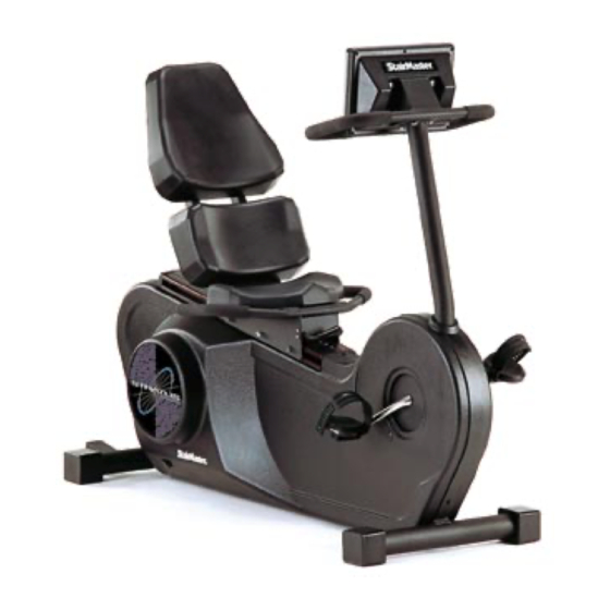
StairMaster ® Stratus cycle ergometer was thoroughly inspected and tested to ensure proper operation. The major parts of the StairMaster Stratus 3300 CE and 3900 RC are shown in Figures 1 and 2. Figure 1: Major Parts, 3300 CE Page 3... -
Page 11: Table 1: Specifications
For example, the drive chain is located on the right side of the machine. The dimensions of the machine are listed in Table 1. Table 1. Dimensions of the Stratus Systems Cycle Ergometer 3300 CE 3900 RC... -
Page 12: Installation Instructions
INSTALLATION INSTRUCTIONS Assemble your machine before use. Machines shipped outside the United States need to be uncrated before they can be assembled; refer to the “Uncrating Instructions” included with your machine for the details. Remove all shipping material and the battery charger from the console. -
Page 13: Basic Operating Instructions
BASIC OPERATING INSTRUCTIONS ADJUSTMENTS ® You should check two adjustments before using your StairMaster Stratus systems cycle ergometer: the seat height and the pedal footstrap length. Seat Height Adjustment on the Stratus 3300 CE Cycle Ergometer Sit on the seat. Put both feet onto the pedals and into the footstraps. Pedal slowly and then stop when one leg is extended and your foot is as close to the floor as possible. -
Page 14: The Attract Mode
If you need to make additional adjustments, repeat the process with the inside mounting holes of the footstrap. THE ATTRACT MODE All workouts on the StairMaster ® Stratus cycle ergometer start from the AT- TRACT mode. The console displays an EKG signal or scrolls a message in the text bar when it is in the ATTRACT mode. - Page 15 BASIC OPERATING INSTRUCTIONS Position yourself comfortably on the bike and begin pedaling. Select the MANUAL exercise program so you can control the pace of your first workout and get used to the exercise motion. Console Set-Up Press [MANUAL] and then press [ENTER]. The console will prompt you to enter your body weight.
-
Page 16: General Exercise Guidelines
GENERAL EXERCISE GUIDELINES SETTING A GOAL The first step to a successful exercise program is to set realistic goals and objectives. Are you wanting an exercise program that is geared to build muscle, maintain muscle tone, or lose weight? In order to ensure that you fully receive all the benefits of a sound exercise program, you need to first identify the existence (if any) of risk factors that may influence the design of your exercise program. -
Page 17: Exercise Principles
-Maintenance Stage - 6 months plus; moderate to high intensity; moderate to high duration. *Note: Some of the material contained in this section is adapted from The StairMaster ® Fitness Handbook 2nd Ed. , James A Peterson, and Cedric X. Bryant (editors), Sagamore Publishing, 1995. -
Page 18: Contact Heart Rate (Optional)
CONTACT HEART RATE ® The StairMaster Stratus Systems cycle ergometer features an optional digitized contact heart rate monitoring system. Through the use of stainless steel sensors built into the upper handles and sophisticated software, heart rate can be checked at any time during a workout. -
Page 19: Polar ® Heart Rate
® POLAR HEART RATE ® ® The StairMaster Stratus cycle ergometer features Polar heart rate monitoring. The system consists of the receiver, located on the stepper, and a transmitter belt (purchased separately), worn across your chest. The transmit- ter belt senses the heart beat and sends a signal to the receiver. Your heart rate, in beats per minute, is shown on the console text bar. -
Page 20: Console
STRATUS SYSTEMS CONSOLE ® The StairMaster Stratus systems console is divided into four sections: the text bar, the display, the function keypad and the exercise program keypad (see Figure 4). Figure 4: Stratus Systems Console TEXT BAR Information regarding workout statistics and data entry is displayed or scrolled across the text bar. -
Page 21: Function Keypad
STRATUS SYSTEMS CONSOLE Function keypad The function keypad is located on the right side of the console. Nine of the keys on the keypad have two pieces of information on them—a number and a workout statistic. Before the exercise program begins, the numbers are used to enter data in response to the console prompts. - Page 22 STRATUS SYSTEMS CONSOLE about 35 milliliters per kilogram per minute. During a workout, this key shows the current MET level. During the workout summary, the average MET level is displayed. Calories. Provides a running total of the number of Calories burned during a workout.
-
Page 23: Exercise Program Keypad
STRATUS SYSTEMS CONSOLE EXERCISE PROGRAM KEYPAD The purple exercise keypad is located below the display and to the left of the function keypad. While the console is in the ATTRACT mode, press one of the exercise program keys to preview the desired workout. - Page 24 STRATUS SYSTEMS CONSOLE Fit Test The Fit Test is a program developed by the YMCA to estimate your maximum aerobic capacity based on your heart rate response to submaximal exercise. Start the Fit Test by pressing [FIT TEST], [ENTER]. You will be prompted to enter your weight, age, and gender after a short message is scrolled across the text bar.
-
Page 25: Table 2: Fitness Rating Norms
STRATUS SYSTEMS CONSOLE Table 2. Fitness Rating Norms for Stratus Systems Cycle Ergometer Aerobic Fitness Test (METs) Rating Fair Average Above Average Superior Gender/Age 20-29 <10.8 11.1-12.3 12.6-16.0 16.3-19.7 20.0+ 30-39 <9.7 10.0-11.1 11.4-14.6 14.8-18.3 18.6+ 40-49 <8.6 8.8-10.0 10.3-13.4 13.7-17.1... -
Page 26: Figure 5: Fat Burner
STRATUS SYSTEMS CONSOLE The Fat Burner program (Figure 5) is a 60 interval workout designed for people just starting a weight control program. The Fat Burner Plus program (Figure 6) is similar but has 90 intervals. It is meant for the longer workouts you will need as your fitness level increases. -
Page 27: Figure 6: Fat Burner Plus
STRATUS SYSTEMS CONSOLE Figure 6a: Fat Burner Plus, Screen 1 Figure 6b: Fat Burner Plus, Screen 2 Figure 6c: Fat Burner Plus, Screen 3 Page 20... -
Page 28: Figure 7: Rolling Hills
STRATUS SYSTEMS CONSOLE Rolling Hills (Figure 7) is a 30 interval workout with gradual speed changes. It is geared for those who are just starting to exercise or for those who need an easy day of recovery exercise. Figure 7: Rolling Hills... -
Page 29: Figure 8: Aerobic Training
STRATUS SYSTEMS CONSOLE Aerobic Training (Figure 8) is a 60 interval workout with slightly more varied speed changes. It is ideal for those long, slow workouts to increase your aerobic capacity. Figure 8a: Aerobic Training, Screen 1 Figure 8b: Aerobic Training, Screen 2... -
Page 30: Figure 9: Cross Country
STRATUS SYSTEMS CONSOLE Cross Country and Speed Training (Figures 9 and 10) are 90 interval workouts with lots of speed changes to get your legs moving. Think of the terrain you would find on a hike cross country. Figure 9a: Cross Country, Screen 1... -
Page 31: Figure 10: Speed Training
STRATUS SYSTEMS CONSOLE Figure 10a: Speed Training, Screen 1 Figure 10b: Speed Training, Screen 2 Figure 10c: Speed Training, Screen 3 Page 24... -
Page 32: Road Race
STRATUS SYSTEMS CONSOLE ROAD RACE The Road Race is a unique program that places the user in a race against a computer pacer. The Road Race uses a resistance system that increases the resistance as you pedal faster, just like a real bicycle. The faster you pedal, the heavier the resistance, and the faster you will travel. -
Page 33: Custom Exercise Programs
STRATUS SYSTEMS CONSOLE CUSTOM EXERCISE PROGRAMS The console has enough memory space for nine custom exercise programs. Only the exercise profile is saved. You must enter your body weight, the intensity level, and the workout time when you use the custom program. Custom programs have a quick start option, but the time is limited to 15 minutes. -
Page 34: Custom Scrolling Message
STRATUS SYSTEMS CONSOLE CUSTOM SCROLLING MESSAGE The message that scrolls across the text bar during the ATTRACT mode can be replaced with a message of your choice. The console accepts messages up to 128 characters in length, including spaces. To program your message: Encode your message using the character codes listed in Table 3. -
Page 35: Editing The Scrolling Message
STRATUS SYSTEMS CONSOLE Table 3. Character Codes for the Scrolling Message EDITING THE SCROLLING MESSAGE While the console is in the ATTRACT mode, press [+ ARROW], [7], [6], [0], [7], [ENTER] to display the first character of the message onto the text bar. -
Page 36: Set Maximum Workout Length
STRATUS SYSTEMS CONSOLE To erase the entire message, press [+ ARROW], [1], [0], [5], [ENTER] while in the ATTRACT mode. The edited message will scroll across the text bar. If you have erased the entire message, the text bar area will be blank during the ATTRACT mode. -
Page 37: Console Codes
STRATUS SYSTEMS CONSOLE console is in the ATTRACT mode, set the console for foreign language prompts or metric units by pressing the [+ ARROW], [9], [7], [6], [0], [ENTER] and then [1], [ENTER]. Press [+ ARROW], [9], [7], [6], [0], [ENTER] and then [0] to change back to English units. -
Page 38: Maintenance Instructions
All references to the right or the left side and to the front or the back of the Stratus systems cycle ergometer are made as if you were sitting on the machine ready to exercise. For example, the drive chain is on the right side of the bike. -
Page 39: Initial Service
INITIAL SERVICE Upon receiving your new Stratus systems cycle ergometer, use a soft, clean towel to wipe off the dust that may have accumulated during shipping. Your new machine will require minor assembly. Refer to the “Installation Instructions”... - Page 40 The salt in perspiration will damage unpainted surfaces. Repair the damaged area with a ® touch-up paint kit provided by StairMaster Sports/Medical Products, Inc. (part number 22181). Inspect the pedal footstraps at both the inside and outside attachment sites.
- Page 41 MAINTENANCE INSTRUCTIONS Quarterly Maintenance Clean and thoroughly lubricate the drive chain and adjust the chain tension every three months. Follow the chain removal and tensioning procedures in the “Parts Removal and Replacement” section. Use a degreaser to clean the accumulated grime from the chain. Lubricate the chain with a spray-on chain lubricant such as Tri-Flow ™...
-
Page 42: Table 5: Preventive Maintenance Schedule
MAINTENANCE INSTRUCTIONS Table 5. Preventive Maintenance Schedule PART RECOM M ENDED FREQUENCY CLEANER LUBRI CANT ACTI ON Co n s o l e Wi p e c l e a n Da i l y Wa t e r N/ A Co v e r s Cl e a n a n d i n s p e c t Da i l y... -
Page 43: Troubleshooting Guidelines
(425) 823-1825. SYSTEMATIC ELECTRICAL TROUBLESHOOTING The electrical system of your Stratus systems cycle ergometer has five major components: the power control board, the alternator, the load resistor, the main cable assembly, and the console. In order to identify the component that is causing the problem, you must systematically test the entire system. -
Page 44: Troubleshooting
TROUBLESHOOTING Measure VDC between test points 7 and 12 of the power control board for a minimum of 6.0 VDC. Test pins 1 and 7 of the main cable at the console connection for a minimum of 6.0 VDC. Reconnect the main cable to the console. Verify that the inductive switch is adjusted to within 1/32"... -
Page 45: Systematic Mechanical Troubleshooting
Check the main cable assembly for continuity and cross check each wire in the cable to check for shorted wires (see the wiring ® diagram ). Call StairMaster Customer Service at (800) 331-3578 for assistance. International customers should contact their local distributors. - Page 46 TROUBLESHOOTING Verify that the jam nut on the flywheel and the alternator/flywheel assembly brackets are tight. Adjust the inductive switch to 1/32" from the speed sensor disk. Loosen the nyloc nut of the J-bolt assembly (see Figure 22) and the nut and bolt that mount the alternator/flywheel brackets to the frame (see Figure 24).
-
Page 47: Console Diagnostic Tests
CONSOLE DIAGNOSTIC TESTS The following tests must be performed while the console is in the DIAGNOSTIC mode. To activate the DIAGNOSTIC mode, press the [+ ARROW], [1], [0], [7], [ENTER]. If the console fails any test, the console should be replaced or ex- changed. - Page 48 CONSOLE DIAGNOSTIC TESTS Firmly press each button. If the LED corresponding to the button you pushed does not light up, the keypad is bad and the console must be replaced. Pressing the [CLEAR] button will light that LED and then end the keypad test 10 seconds later.
- Page 49 CONSOLE DIAGNOSTIC TESTS Contact Heart Rate Test The contact heart rate system is made up of the console and the contact heart rate handles. You can test each component by performing the following steps: While the console is in the ATTRACT mode (noted by a simulated EKG signal in the console display), or at the “SELECT A WORKOUT”...
- Page 50 CONSOLE DIAGNOSTIC TESTS While the console is in the ATTRACT mode (noted by a simulated EKG signal in the console display), or at the “SELECT A WORKOUT” prompt, press [+INCREASE], [1], [0], [8], [ENTER]. A flashing should be displayed in the console text bar. Your heart rate, in beats per minute, will show next to the heart icon.
-
Page 51: Parts Removal And Replacement
PARTS REMOVAL AND REPLACEMENT COVERS 3300 CE The Stratus 3300 CE cycle ergometer is protected by four plastic covers: two large side covers and two smaller neck covers. Refer to Figure 12 for the fastener locations. The neck covers are held in place with six reusable fasteners. Slide either end of the fastener removal tool under the edge of the head pin and pull the pin out about halfway (see Figure 11). -
Page 52: Console
PARTS REMOVAL AND REPLACEMENT 3900 RC The Stratus 3900 RC cycle ergometer is protected by two plastic side covers. Refer to Figure 13 for the fastener locations. The side covers are held in place with six reusable fasteners. Slide either end of the fastener removal tool under the edge of the head pin and pull the pin out about halfway (see Figure 11). -
Page 53: Handlebar Assembly
PARTS REMOVAL AND REPLACEMENT HANDLEBAR ASSEMBLY 3300 CE Remove the console and neck covers. Loosen and remove the four screws and flat washers from the frame tube (see Figure 14). Hold onto the handlebar with both hands and remove the handlebar assembly from the frame tube. -
Page 54: Seat
PARTS REMOVAL AND REPLACEMENT SEAT 3300 CE Loosen and remove the four mounting nuts and lock washers located underneath the seat (see Figure 18). Remove the seat. Reverse the steps to reinstall. 3900 RC The seat pads can be removed while the seat is in the seat track. Loosen and remove the four mounting bolts from each seat pad and lift the pad free. -
Page 55: Seat Location Post (3300 Ce Only)
PARTS REMOVAL AND REPLACEMENT SEAT LOCATION POST (3300 CE ONLY) Pull the seat adjustment knob out and raise the seat. Insert a phillips screwdriver into one of the holes in the seat post that are visible above the seat tube cap (see Figure 18). Gently lower the seat so that the seat is held up by the screwdriver. -
Page 56: Seat Track (3900 Rc Only)
PARTS REMOVAL AND REPLACEMENT Push the seat post forward so the seat adjustment bushing is moved slightly forward in the bushing housing. Insert a standard screwdriver between the front of the seat post and the mainframe to pry the seat adjustment bushing into the bushing housing and out of the way of the nylon seat post guides. -
Page 57: Intermediate Shaft Assembly
PARTS REMOVAL AND REPLACEMENT Check the tension in the drive chain for a total of 1" (2 cm) of deflection at the midpoint of the lower chain section (see Figure 20). To adjust the chain tension, loosen the nuts at the top and the bottom of the intermediate shaft bracket. -
Page 58: Pedals
PARTS REMOVAL AND REPLACEMENT Inspect the freewheel for smoothness of operation in the counter clockwise direction and for positive engagement in the clockwise direction. Use a freewheel tool to remove the freewheel from the Poly-V pulley, if replacement is necessary. Reverse the steps to reinstall the parts. - Page 59 PARTS REMOVAL AND REPLACEMENT Loosen and remove the bottom bracket jam nut located on the left side of the crank (see Figure 23). This nut has reverse threads; loosen it by turning it clockwise. Remove the round, metal crank shield from the left side of the crank. Remove the bearing clamps by loosening the allen bolts from the left side clamp.
- Page 60 PARTS REMOVAL AND REPLACEMENT Install the round, metal crank shield, the jam nut and the pedal onto the left side of the crank. Remember, the jam nut and the pedal have reverse threads (tighten them in the counterclockwise direction). Adjust the side play in the crank by tightening or loosening the left side bearing nut with a 32-mm cone wrench.
-
Page 61: Grounding Instructions
WITH THIS MACHINE. IF IT WILL NOT FIT THE AVAILABLE OUTLET, HAVE A PROPER OUTLET INSTALLED BY A QUALIFIED ELECTRICIAN. The Stratus systems cycle ergometer is designed for use on a nominal 120-volt circuit, and has a grounding plug that looks like the plug illustrated in sketch A below.* A temporary adapter that looks like the adapter illustrated in... -
Page 62: Notice Of Fcc Compliance
• Consult the dealer or an experienced radio/TV technician for help. WARNING CHANGES OR MODIFICATIONS TO EQUIPMENT NOT ® EXPRESSLY APPROVED BY STAIRMASTER SPORTS/MEDICAL PRODUCTS, INC. COULD VOID THE USER'S AUTHORITY TO OPERATE THIS EQUIPMENT. Canadian Doc Class B Compliance... -
Page 63: Important Phone Numbers
IMPORTANT PHONE NUMBERS If you need assistance, please have both the serial number of your machine and the date of purchase available when you contact the appropriate StairMaster Health and Fitness Products™ office listed below. OFFICES IN THE UNITED STATES CORPORATE HEADQUARTERS... -
Page 64: Battery Recycling Centers
BATTERY RECYCLING CENTERS After installing a new battery, you will need to properly dispose of (recycle) your old lead-acid battery. Most federal and state regulations require lead-acid batteries be recycled. Do not throw away old batteries. Lead is a heavy metal and is toxic to living organisms. - Page 65 BATTERY RECYCLING CENTERS STATE ADDRESS PHONE NUMBER New Jersey 131 Industrial Ave. (201) 641-5900 Hasbrouck Hgts., NJ 07604 New York 26 Corporate Circle (315) 437-1788 E. Syracuse, NY 13057 Ohio, Central Rickenbacker ANG (513) 851-3838 Bldg. 1073 Columbus, OH 43217 Ohio, North 2635 Hamilton Ave.
-
Page 66: Figures 11 - 24
FIGURES Figure 11: Cover Fasteners Page 59... -
Page 67: Figure 12: Cover Fastener Location, 3300 Ce
FIGURES Figure 12: Cover Fastener Locations, 3300 CE Page 60... -
Page 68: Figure 13: Cover Fastener Location, 3900 Rc
FIGURES Figure 13: Cover Fastener Location, 3900 RC Page 61... -
Page 69: Figure 14: Right Side View, 3300 Ce
FIGURES Figure 14: Right Side View, 3300 CE Page 62... -
Page 70: Figure 15: Left Side View, 3300 Ce
FIGURES Figure 15: Left Side View, 3300 CE Page 63... -
Page 71: Figure 16: Right Side View, 3900 Rc
FIGURES Figure 16: Right Side View, 3900 RC Page 64... -
Page 72: Figure 17: Left Side View, 3900 Rc
FIGURES Figure 17: Left Side View, 3900 RC Page 65... -
Page 73: Figure 18: Seat Adjustment Pin Assembly, 3300 Ce
FIGURES Figure 18: Seat Adjustment Pin Assembly, 3300 CE Page 66... -
Page 74: Figure 19: Seat Assembly, 3900 Rc
FIGURES Figure 19: Seat Assembly, 3900 RC Page 67... -
Page 75: Figure 20: Drive Chain Tension
FIGURES Figure 20: Drive Chain Tension Page 68... -
Page 76: Figure 21: Intermediate Shaft Assembly
FIGURES Figure 21: Intermediate Shaft Assembly Page 69... -
Page 77: Figure 22: J Bolt Assembly
FIGURES Figure 22: J-Bolt Assembly Page 70... -
Page 78: Figure 23: Crank Assembly
FIGURES Figure 23: Crank Assembly Page 71... -
Page 79: Figure 24: Alternator/Flywheel Assembly
FIGURES Figure 24: Alternator/Flywheel Assembly FLYWHEEL NO LONGER AVAILABLE Page 72... -
Page 80: Wiring Diagram
WIRING DIAGRAM Wiring Diagram WIRING SCHEMATIC BATTERY CHARGER CONSOLE FUSE POWER CONTROL BOARD ALTERNATOR LOAD INDUCTIVE BATTERY RESISTOR SWITCH PIN 1 – VDC + (WHT) PIN 2 – GROUND (BLK) PIN 2 – GROUND (BLK) PIN 3 – N/C PIN 3 – VDC (WHT) PIN 1 –...
Need help?
Do you have a question about the Stratus Systems and is the answer not in the manual?
Questions and answers