
Related Manuals for Matrix MX-A5x


Summary of Contents for Matrix MX-A5x
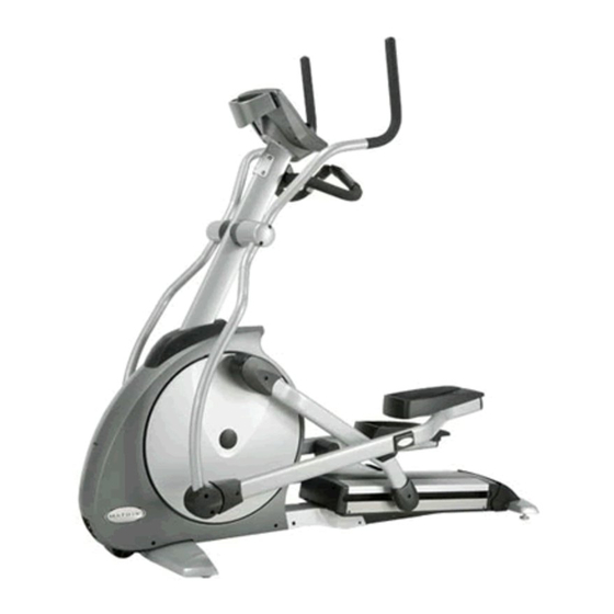
- Page 1 A s c e n t t r A i n e r & i n c l i n e e l l i p t i c A l O W n e r ’ s M A n U A l...
-
Page 3: Table Of Contents
5: MOvinG tHe Unit 5.1 MX-A5x Ascent Trainer ..................5.2 MX-I5x Incline Elliptical ................... cHApter 6: seriAl nUMBer lOcAtiOn 6.1 MX-A5x Ascent Trainer ..................6.2 MX-I5x Incline Elliptical ................... cHApter 7: MX-A5x specificAtiOns AnD AsseMBly steps 7.1 Model Specifications ..................7.2 Fasteners and Assembly Tools ................7.3 Assembly Steps ....................7.4 Optional Entertainment Accessory ..............cHApter 8: MX-i5x specificAtiOns AnD AsseMBly steps 8.1... -
Page 5: Chapter 1: Important Safety Instructions
This elliptical is intended for commercial use. To ensure your safety and ucts to instruct all individuals, whether they are the end user or supervising protect the equipment, read all instructions before operating the MATRIX personnel, on proper usage of the equipment. elliptical. It is recommended that all users of Matrix Fitness Systems exercise equip- When using an electrical product, basic precautions should always be followed ment be informed of the following information prior to its use. including the following: DAnGer: To reduce the risk of electric shock: Always unplug this equipment 1.2 prOper UsAGe... -
Page 6: Electrical Requirements
Fitness Systems for a replacement. 1-866-693-4863, www.matrixfitness.com 1.5 DeDicAteD circUit/electricAl reqUireMent infO MAintAin All eqUipMent Preventative maintenance is the key to smooth operating equipment. Equipment needs to be inspected at regular intervals. All Matrix Ascent Trainer units require the use of a 15 amp or 20 amp Defective components must be replaced immediately. Improperly working “dedicated circuit,” with a non-looped (isolated) neutral/ground, for the equipment must be kept out of use until it is repaired. Ensure that any person(s) power requirement. Quite simply this means that each outlet you plug... -
Page 7: Care And Maintenance Instructions
Teflon based spray lubricant Mild, water soluble, detergent – such as “Simple Green”, or other Matrix approved Vacuum/clean under cover Check connecting joints Check locking pins product Check motor drive belt Remove covers, check belts Check pulleys Teflon based spray lubricant such as “Super Lube”, or other Matrix approved product Check running belt Check pedal & crank Inspect upholstery Vacuum cleaner w/extendable hose and crevasse tool attachment Flip/replace deck Check/lube seat adjustment Check/tighten hardware Please find the worksheet sample for our equipment provided in this manual... -
Page 8: Chapter 3: Using The Console
cHApter 3: U sing onsole 3.1 cOnsOle DescriptiOn 3.2 incline fUnctiOn Changing the incline will produce a wide variety of challenging workouts. At All programs follow the same basic steps. 0 incline, you can expect a smooth, easy and low-impact pedal motion. At higher incline levels, longer stride and higher step-up challenge the user with Select program key. • a more focused glute workout. Enter user information (age, weight). • How the incline works A5x - by pressing the Up elevation arrow key(inwhite) • both incline arms pivot towards the rear of the machine. This increases both Choose workout time. • stride length and step on height. •... -
Page 9: Quick Start
cHApter 3: U sing onsole 3.6 fit test 3.3 qUick stArt FIT TEST program allows you to measure your fitness. Press to immediately begin workout. Workout, resistance level and incline level will automatically go to default settings (see manager mode for default Follow these easy steps to enter the Fit Test Program. settings). QUICK START will not prompt the user for age, weight or level settings. step 1: Select the fit test button. -
Page 10: Target Hr
cHApter 3: U sing onsole 3.7 tArGet Hr Men’s OUtpUt tABle fOr test #1 A5x and I5x have digital contact and wireless heart rate monitoring capabilities as AGE EXCELLENT ABOVE AVERAGE BELOW POOR standard equipment. AVERAGE AVERAGE To use heart rate monitor, locate the metal sensors located on the fixed • handlebars. 13-14 >2700m 2400-2700m 2200-2399M 2100-2199M <2100M 15-16 >2800m 2500-2800m 2300-2499M 2200-2299M <2200M 17-20 >3000m 2700-3000m 2500-2699M 2300-2499M <2300M... -
Page 11: Constant Watts
cHApter 3: U sing onsole 3.8 cOnstAnt WAtts Resistance level is set by the user and constantly changes to reflect stride speed. As stride speed (spM) increases, resistance decreases while output wattage stays the same. In turn, if stride speed decreases then resistance increases. -
Page 12: Using Manager Mode
Press qUick stArt again to exit manager mode. • (example changing default time from 20:00 - 30:00 minutes). p7: Accumulated distance - Total distance of all programs. • p8: Accumulated time - Total accumulated program time displayed in hours. • p9: Display language - • Select between English, Spanish, French Italian, Dutch and German. p10: software version - • Current version of software. Refer to this when calling Matrix Technical Service. p11: incline calibration - • Default display is Off. Selecting On will automatically calibrate the incline motor (s) to factory settings. Use this feature when actual elevation does not match console display. p12: incline reset - • This is a software feature that resets machine elevation to 0 degrees after 30 seconds of user inactivity. During incline reset, movement can be stopped by pressing any console key. Display will scroll “HOlD select tO resUMe”. To resume reset to 0 degrees, hold “select”key for three seconds. -
Page 13: Engineering Mode
- 100 p14: error code - nOte: DEFAULT TIME will update to the same as MAX TIME if MAX TIME is less than DEFAULT TIME. 4.3 enGineerinG MODe to enter engineering mode, hold the Up and DOWn elevation keys for three seconds until “MAnAGer” appears on the middle LED display. Press the DOWn arrow key and “errOr cOntrOl” will appear on middle LED display. error control, Do not use this mode unless you are a qualified technician. Error control will determine if a machine is disabled once Class A or Class B errors are registered by the software. incline record, log of incline motor and total program activity. This record holds the total number of hours for each program (MANUAL, ROLLING, INTERVAL, etc.) as well as incline motor activity in hours. This can be a useful tool for the club manager of trainer when reviewing machine usage. • To enter INCLINE RECORD, press select when incline recOrD is displayed. • Totals are stored permanently unless reset by a technician. To reset error codes, hold MAnUAl and rAnDOM keys for three seconds. Refer to accumulated hours when calling Matrix technical service for assistance. (Insert chart) incline tuner, Do not use this mode unless you are qualified technician. Incline Tuner allows calibration and resetting of the incline motor range of motion. service 1,2,3,4 are described in the Matrix Technical Service Guide. -
Page 14: Chapter 5: Moving The Unit
6: s oving erial umber ocation 5.1 MX-A5x Ascent trAiner 6.1 MX-A5x Ascent trAiner A5x - Two hand holds are located just above the MATRIX logo on the rear legs. SERIAL # PLACEMENT LIFT HANDLES The A5x weights 390lbs. To avoid injury to the user and the unit, be sure to have proper assistance to move the unit. 6.2 MX-i5x incline ellipticAl 5.2 MX-i5x incline ellipticAl... -
Page 15: Model Specifications
7: MX-A5 pecifications and ssembly teps 7.1 MX-A5x Ascent trAiner specificAtiOns USER INTERFACE STRIDE LENGTH 21 - 24” INCLINE RANGE 30˚ CONSTANT RATE OF ACCELERATION CONTACT HEART RATE SENSORS TELEMETRIC HEART RATE RECEIVER REPLACEABLE FOOTPEDAL INSERTS 3.75” Q-FACTOR MUTLI-POSITION DUAL ACTION... -
Page 16: Fasteners And Assembly Tools
7: MX-A5 pecifications and ssembly teps 7.2 MX-A5x Ascent trAiner fAsteners & AsseMBly tOOls PART # SKETCH DESCRIPTION NOTES 6mm ALLEN WRENCH PHILLIPS DRIVER OPEN WRENCH (#13) HEX SOCKET HEAD CAP (M8 x 15L) HEX SOCKET HEAD CAP (M8 x 20L) -
Page 17: Assembly Steps
7: MX-A5 pecifications and ssembly teps 7.3 MX-A5x Ascent trAiner AsseMBly steps STEP 1 STEP 2 Lightly grease... - Page 18 7: MX-A5 pecifications and ssembly teps 7.2 MX-A5x Ascent trAiner AsseMBly steps FINAL ASSEMBLY STEP 3 N51 x4 Water Bottle Holder...
-
Page 19: Optional Entertainment Accessory
7: MX-A5 pecifications and ssembly teps 7.4 MX-A5x OptiOnAl entertAinMent AccessOry... -
Page 20: Chapter 8: Mx-I5X Specifications And Assembly Steps
cHApter 8: MX-i5 pecifications and ssembly teps 8.1 MX-i5x incline ellipticAl trAiner specificAtiOns USER INTERFACE STRIDE LENGTH 21 - 23” INCLINE RANGE 17˚ CONSTANT RATE OF ACCELERATION CONTACT HEART RATE SENSORS TELEMETRIC HEART RATE RECEIVER REPLACEABLE FOOTPEDAL INSERTS 3.75” Q-FACTOR MUTLI-POSITION DUAL ACTION HANDLE BAR DESIGN AND ERGO-BEND STATIONARY... -
Page 21: Fasteners And Assembly Tools
cHApter 8: MX-i5 pecifications and ssembly teps 8.2 MX-i5x incline ellipticAl trAiner fAsteners & AsseMBly tOOls PART # SKETCH DESCRIPTION NOTES ALLEN WRENCH [ 5mm x 120L ] ALLEN WRENCH [ 55L, M3 ] ALLEN WRENCH [ 6mm x 120L, M8 ] OPEN WRENCH [ 13mm, M8 ] #2 PHILLIPS SCREW DRIVER [ 6 x 130L ] BUTTON HEAD MACHINE SCREW [ M5 x 8L ]... -
Page 22: Assembly Steps
cHApter 8: MX-i5 pecifications and ssembly teps 8.3 MX-i5x incline trAiner AsseMBly steps STEP 1 STEP 2 INCLUDED WITH CONSOLE CABLE TIE [ 200L ] Z11x8 Z10x8... - Page 23 cHApter 8: MX-i5 pecifications and ssembly teps 8.3 MX-i5x incline trAiner AsseMBly steps STEP 3 STEP 4...
- Page 24 cHApter 8: MX-i5 pecifications and ssembly teps 8.3 MX-i5x incline trAiner AsseMBly steps STEP 5 FINAL ASSEMBLY Water Bottle Holder Lightly grease...
-
Page 25: Optional Entertainment Accessory
cHApter 8: MX-i5 pecifications and ssembly teps 8.4 MX-i5x OptiOnAl entertAinMent AccessOry... - Page 26 nOtes:...
- Page 27 MAtr iX f itn ess sys te M s cOr p. 1 6 1 0 LAN D MA R K DRI VE CO TTAG E GR O VE W I 53 527 U S A w w w. m a t r i x f i t n e s s . c o m T O L L F R EE 86 6 .
Need help?
Do you have a question about the MX-A5x and is the answer not in the manual?
Questions and answers