Table of Contents
Advertisement
Quick Links
Advertisement
Table of Contents

Related Manuals for Matrix MX-A5x


Summary of Contents for Matrix MX-A5x
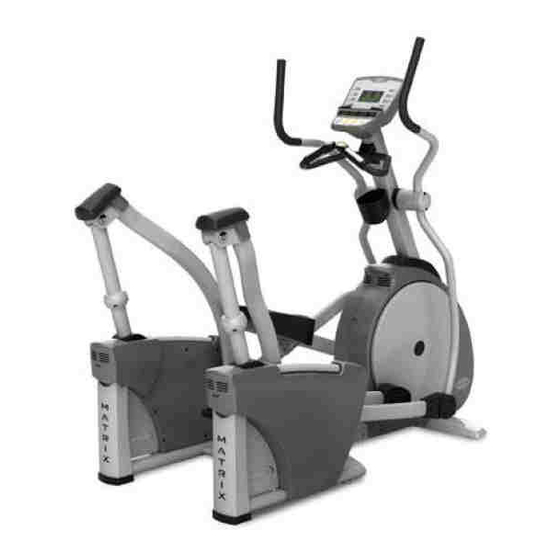
- Page 1 A s c e n t t r A i n e r s e r V i c e M A n U A l...
-
Page 3: Table Of Contents
tAble of contents cHAPter 1: seriAl nUMber locAtion ......................cHAPter 2: MoVing tHe Unit ..........................cHAPter 3: iMPortAnt sAfety instrUctions legal Disclaimer ..............................3 training notice ..............................3 read and save these instructions ......................4 electrical requirements ..........................5 cHAPter 4: PreVentAtiVe MAintenAnce recommended cleaning tips ........................ - Page 4 ................................49 10.3 Ascent trainer swing Arm/Actuators ....................... 50 10.4 fasteners & Assembly tools .......................... 51 10.5 MX-A5x Ascent trainer Assembly steps ....................51 10.6 MX-A5x optional entertainment Accessory ................... 52 cHAPter 11: UPgrADes 11.1 belt tensioner bearing replacement ......................54 11.2...
-
Page 5: Chapter 1: Serial Number Location
1: seriAl nUMber locAtion 1.1 MX-A5x Ascent trAiner seriAl nUMber locAtion seriAl nUMber PlAceMent... -
Page 6: Chapter 2: Moving The Unit
2: MoVing tHe Unit 2.1 MoVing tHe Unit two hand holds are located just above the MAtriX logo on the rear legs. the A5x weighs 390lbs. to avoid injury to the user and the unit, be sure to have proper assistance to move the unit. -
Page 7: Chapter 3: Important Safety Instructions
cHAPter 3: iMPortAnt sAfety instrUctions 3.1 legAl DisclAiMer 3.2 trAining notice... -
Page 8: Read And Save These Instructions
Ascent trainer is intended for commercial use. to ensure your safety • D o not use the equipment in any way other than designed or intended by and protect the equipment, read all instructions before operating the the manufacturer. it is imperative that all Matrix fitness systems equip- MAtriX Ascent trainer. ment is used properly to avoid injury. -
Page 9: Electrical Requirements
15 Amp and 4 units per 20 Amp dedicated circuit.) MAtriX DeDicAteD circUit/electricAl reQUireMent info All Matrix Ascent trainer units require the use of a 15 amp or 20 amp “dedicated circuit,” with a non-looped (isolated) neutral/ground, for the power requirement. -
Page 10: Chapter 4: Preventative Maintenance
• Clean with a soft 100% cotton cloth. kind is qualified to do so. Matrix fitness systems will provide service and maintenance training at our corporate facility upon request or in the field • C lean with soap and water or other non-ammonia based all purpose if proper arrangements are made. -
Page 11: Care And Maintenance Instructions
4.4 PreVentAtiVe MAintenAnce cHecKlist 4.3 cAre AnD MAintenAnce instrUctions facility: in order to maximize life span, and minimize down time, all MAtriX equipment requires regular cleaning, and maintenance items performed on a scheduled basis. this section contains detailed instructions on how to perform... -
Page 12: Chapter 5: Using The Console And Program Description
cHAPter 5: Using tHe console AnD ProgrAM DescriPtion 5.1 console DescriPtion 5.2 incline fUnction changing the incline will produce a wide variety of challenging workouts. At All programs follow the same basic steps. 0 incline, you can expect a smooth, easy and low-impact pedal motion. At higher incline levels, longer stride and higher step-up challenge the user with select program key. -
Page 13: Quick Start
cHAPter 5: Using tHe console AnD ProgrAM DescriPtion 5.3 QUicK stArt 5.6 fit test Press to immediately begin workout. Workout, resistance level and incline fit test program allows you to measure your fitness. level will automatically go to default settings (see manager mode for default follow these easy steps to enter the fit test Program. -
Page 14: Men's Output Table For Test #1
cHAPter 5: Using tHe console AnD ProgrAM DescriPtion 5.7 tArget Hr Men’s oUtPUt tAble for test #1 A5x and i5x have digital contact and wireless heart rate monitoring capabilities as AGE EXCELLENT ABOVE AVERAGE BELOW POOR standard equipment. AVERAGE AVERAGE to use heart rate monitor, locate the metal sensors located on the fixed •... -
Page 15: Constant Watts
cHAPter 5: Using tHe console AnD ProgrAM DescriPtion 5.8 constAnt WAtts resistance level is set by the user and constantly changes to reflect stride speed. As stride speed (sPM) increases, resistance decreases while output wattage stays the same. in turn, if stride speed decreases then resistance increases. -
Page 16: Chapter 6: Manager Mode
cHAPter 6: MAnAger MoDe 6.1 Using MAnAger MoDe example changing default time from 20:00 - 30:00 minutes to enter manager mode, hold the UP and DoWn level keys • (highlighted in white below) for three seconds until “MAnAger” appears on the middle leD display. QUICKSTART Press the UP and DoWn elevation keys to scroll •... -
Page 17: Manager Screen Descriptions
MAnUAl and rAnDoM keys for three seconds. refer to these error codes when calling Matrix technical service for assistance. P15: lcb Version - Display will show lcb.Ver XX yyy. -
Page 18: Chapter 7: Engineering Mode
Matrix technical service for assistance. (insert chart) incline tuner, Do not use this mode unless you are qualified technician. incline tuner allows calibration and resetting of the incline motor range of motion. service 1,2,3,4 are described in the Matrix technical service guide. -
Page 19: Chapter 8: Troubleshooting
cHAPter 8: troUblesHooting 8.1 electricAl DiAgrAM... -
Page 20: Lcb3 Led Place & Definition
cHAPter 8: troUblesHooting eleVAtor Wire 3 0 0 . V W - 1 . C S A T Y P E , P V C ecb loAD Wire 4 5 0 1 . 2 5 M ( 0 . 1 8 / 5 0 , L F DigitAl cAble (console cable) 1 3 5 0... -
Page 21: Software Settings
cHAPter 8: troUblesHooting 8.2 A5x(eP72) lcb3 leD PlAce AnD Definition 8.3 softWAre settings Unit does not record distance or rPM if unit resets after 30 seconds despite pedaling verify “incline reset” is on in manager mode (P12). Perform console leD segment test to verify console can display rPM (service 1 in engineering mode) select another program and begin pedaling. -
Page 22: Entertainment
Verify that your tV equipment is Matrix brand equipment. compare your tV to the tV in figure A. compare your controller to figure b. if your equipment looks different contact Matrix or the manufacturer of your tV equipment if known. -
Page 23: Entertainment - Picture Fuzzy Or Unclear
cHAPter 8: troUblesHooting 8.5.1 entertAinMent – PictUre fUZZy or UncleAr Using a verified piece of coax cable, hook directly from the tV to the jack that feeds your equipment. (this bypasses internal connections for your machine or tV stand.) if this clears your picture move to step 3. if not, connect the cable to a known good cable jack. -
Page 24: Entertainment - Tv Will Not Turn On
(tV light is after the x in the “Matrix” logo, controller light is next to power button). status lights should be red when off or in standby mode, and green when the tV is powered on. -
Page 25: Resistance Function
Attempt to turn on the tV again using the on/off button. if tV powers on contact Matrix for parts to resolve the “tV lockup problem”. 2. if tV does not power on check controller and cable by swapping them from a known working unit if possible. -
Page 26: Heart Rate Failure/Intermittent
cHAPter 8: troUblesHooting 8.7 HeArt rAte fAilUre/interMittent 8.8 incline fAilUre note – contact (hand grip) heart rate takes approximately 15 seconds to acquire. Due to variations in physiology, some people take longer and there is a small percentage of the population that will not be able to register a heart rate. -
Page 27: Leveling The A5X
cHAPter 8: troUblesHooting 8.9 leVeling tHe A5X on a new A5x Ascent trainer, the rubber foot on the underside of the center of the frame should be flush against the frame itself. 1. As pictured in fig. 1, it has a washer that eliminates pressure againt the nut that is inside the frame. -
Page 28: Chapter 9: Part Replacement Guide
cHAPter 9: PArt rePlAceMent gUiDe 9.1 front DisK reMoVAl Use caution when detaching pedal arm and link arm. Assemblies are heavy and can cause injury. 1. remove link arm/pedal arm plastic caps (figures A and b) note: round dual-action end cap requires a short phillips screwdriver to reach and remove inner screw. -
Page 29: Front Disk Removal - Continued
24mm locking nut and washer by turning counter clockwise. (figure g) thread Matrix disk removal tool into center hub. (figures H and i) note: there are two different removal tools. if you have 3 tapped holes on your center hub see fig i, if the inside of the hub is tapped (no holes) see fig H. -
Page 30: Front Disk Removal - Continued
cHAPter 9: PArt rePlAceMent gUiDe 9.1 front DisK reMoVAl – continUeD remove the 12 screws that hold the front shrouds in place. (figure l) 10. remove the front shrouds for frame access. (figure M) 11. reverse steps 1-10 to reassemble machine, securing all connections and fasteners as needed. -
Page 31: Lcb (Lower Control Board) Removal And Installation
cHAPter 9: PArt rePlAceMent gUiDe 9.2 lcb (loWer control boArD) reMoVAl AnD instAllAtion turn off power and disconnect the cord from the machine. remove both front disks from machine as outlined in section 9.1. (figures A and b). remove lcb cover (2 screws) to allow wiring access. (figure c) Disconnect all wires from the lcb (7 connections). -
Page 32: Ecb (Electromagnetic Brake) Removal And Installation
cHAPter 9: PArt rePlAceMent gUiDe 9.3 ecb (electroMAgnetic brAKe) reMoVAl AnD instAllAtion turn off power and disconnect the cord from the machine. remove both front disks and plastic shrouds from machine as outlined in section 9.1. (figure A). Unplug ecb (under mast connection point) from wire harness. (figure b) loosen 11mm nut on tension loop bolt. -
Page 33: Ecb Removal And Installation - Continued
cHAPter 9: PArt rePlAceMent gUiDe 9.3 ecb reMoVAl AnD instAllAtion – continUeD remove the old ecb and install the new ecb from the user’s left side of the frame. (figure f) install the 6 frame mounting bolts loosely & attach belt. (figure g) Attach the tension loop bolt to ecb bracket and tension belt to 120 lbs. -
Page 34: Belts Removal And Installation - Short Belt Run
cHAPter 9: PArt rePlAceMent gUiDe 9.41 belts reMoVAl AnD instAllAtion - sHort belt rUn turn off power and disconnect the cord from the machine. remove front disks from machine as needed. outlined in section 9.1 (figures A (drive belt) and b (ecb belt)). check the unit to see whether you have a short or long belt run. -
Page 35: Belts Removal And Installation - Long Belt Run
cHAPter 9: PArt rePlAceMent gUiDe 9.42 belts reMoVAl AnD instAllAtion - long belt rUn 4 . (options 1-3 on page 30) - to remove the drive belt, loosen the belt tension bolt on the left side of the tension pulley and rotate the pulley counter-clockwise until there is enough slack in the belt to remove it (figures b &c). -
Page 36: Bearing Pulley Assembly Removal And Installation
(figure b) release any bent tabs from locking washer around nut. remove the 75mm nut from the assembly being serviced. Matrix fitness service tool required. (figure c) remove the tapered split ring that is held in place by the nut. (figure D) remove the bearing assembly, and clean any debris from the frame. -
Page 37: Fixed Handlebar Removal And Installation
cHAPter 9: PArt rePlAceMent gUiDe 9.6 fiXeD HAnDlebAr reMoVAl AnD instAllAtion turn off power and disconnect the cord from the machine. remove the console and disconnect the heart rate wires as outlined in section 9.9. remove the two screws holding the plastic handlebar cover in place and remove the cover. -
Page 38: Dual Action Handlebar Removal And Installation
cHAPter 9: PArt rePlAceMent gUiDe 9.7 DUAl Action HAnDlebAr reMoVAl AnD instAllAtion the dual action handlebar (figure A) is attached to the link arm at the bottom bracket and at the mast pivot. see section 9.1 for plastic cover removal. remove the bolt and bushings at the bottom. -
Page 39: Console Removal And Installation
cHAPter 9: PArt rePlAceMent gUiDe 9.8 console reMoVAl AnD instAllAtion turn off power and disconnect the cord from the machine. remove the 4 screws that hold the console to the top of the mast. (figure A) Disconnect the data cable, heart rate, and ground wires. (figure b) Attach the wires to the new console, heart rate wires are labeled r and l. -
Page 40: Console - Overlays & Keypads Removal And Installation
cHAPter 9: PArt rePlAceMent gUiDe 9.8.1 console – oVerlAys & KeyPADs reM0VAl AnD instAllAtion turn off power and disconnect the cord from the machine. Disconnect the console from the machine as outlined in section 9.9 and remove the back of the console. 6 screws (figure A) note: skip this step if not changing keypads. -
Page 41: Console - Overlays & Keypads Removal And Installation - Continued
cHAPter 9: PArt rePlAceMent gUiDe 9.8.1 console – oVerlAys & KeyPADs – reMoVAl AnD instAllAtion - continUeD remove backing from new keypad. (figure f) install new keypad by sliding ribbon through console and aligning keypad with console house – press into place. Attach keypad ribbon to console board by pressing carefully into place. -
Page 42: Console - Ucb (Upper Control Board) & Heart Rate Board Removal And Installation
cHAPter 9: PArt rePlAceMent gUiDe 9.8.2 console – Ucb (UPPer control boArD) & HeArt rAte boArD reMoVAl AnD instAllAtion turn off power and disconnect the cord from the machine. Disconnect the console from the machine as outlined in section 9.8 and remove the back of the console. 6 screws (figure A) inside the back plastic of the console is the Heart rate board, with the wires disconnected pry it loose from the plastic –... -
Page 43: Rear Plastic Removal And Installation
cHAPter 9: PArt rePlAceMent gUiDe 9.9 reAr PlAstic reMoVAl AnD instAllAtion turn off power and disconnect the cord from the machine. to remove the rear plastic shrouds 8 screws must be removed. first remove 3 of the 4 on the outer perimeter, only 1 of the 2 on the rear of the machine need to be removed. -
Page 44: Incline Motor Removal And Installation
Move the swing arm up to rest against the frame so it is clear of the motor. for safety purposes Matrix fitness suggests you secure the arm to the frame even though it will hold itself in place with its own weight. -
Page 45: Incline Motor Removal And Installation - Continued
cHAPter 9: PArt rePlAceMent gUiDe 9.10 incline Motor reMoVAl AnD instAllAtion – continUeD Prepare new motor for installation, new motor will have the nut placed at the end of the screw shaft – Do not move the nut. (figure f) install the new motor using the plastic washers. -
Page 46: Foot Pedals Removal And Installation
cHAPter 9: PArt rePlAceMent gUiDe 9.11 foot PeDAls reMoVAl AnD instAllAtion remove the 4 phillips screws that hold the plastic pedal to the foot plate. (figure A) remove the plastic foot pedal. (figure b) remove the rubber grip. (figure c) clean the foot plate to remove any rubber or debris. -
Page 47: Link Arms & Pedal Arms Removal And Installation
cHAPter 9: PArt rePlAceMent gUiDe 9.12 linK ArMs & PeDAl ArMs reMoVAl AnD instAllAtion to service or replace link arms and pedal arms they should be removed from the machine as an assembly. the pedal arm is noted so as it connects to the front disc assembly. the link arm contains the foot pedal and connects to the dual action arm in the front. -
Page 48: Link Arms & Pedal Arms Removal And Installation - Continued
cHAPter 9: PArt rePlAceMent gUiDe 9.12 linK ArMs & PeDAl ArMs reMoVAl AnD instAllAtion – continUeD remove the 3 bolts (figure f) that hold on the mounting plate. (figure g) note the plastic washer that mounts at the end of the shaft. -
Page 49: Swing Arm Removal And Installation
cHAPter 9: PArt rePlAceMent gUiDe 9.13 sWing ArM reMoVAl AnD instAllAtion to service or replace a swing arm you should first disconnect the link arm from the dual action arm as outlined in the first part of section 9.1. the link arm contains the foot pedal and connects to the dual action arm in the front. -
Page 50: Swing Arm Removal And Installation - Continued
cHAPter 9: PArt rePlAceMent gUiDe 9.13 sWing ArM reMoVAl AnD instAllAtion - continUeD to remove the swing arm from the machine, loosen one of the bolts on either side of the upper pivot joint. (figure f) Holding onto the swing arm, push /pull the pivot shaft out of the bearing housing. -
Page 51: Rear Pivot Arm Removal And Installation
cHAPter 9: PArt rePlAceMent gUiDe 9.14 reAr PiVot ArM reMoVAl AnD instAllAtion turn off power and disconnect the cord from the machine. remove the rear plastic covers as outlined in section 9.9. remove the bolts holding the rear pivot arm to the motor (figure A). -
Page 52: Unit Functionality Testing
cHAPter 9: PArt rePlAceMent gUiDe 9.99 Unit functionality testing once the Ascent trainer is fully assembled and properly placed on the floor use the following instructions to test the machine: Without hitting start or entering any exercise modes, stand on machine and hold handlebars while initiating movement to simulate exercising. -
Page 53: Chapter 10: Exploded Diagrams
cHAPter 10: eXPloDeD DiAgrAMs 10.1 DriVe AsseMbly 10.2 console... -
Page 54: Ascent Trainer Swing Arm/Actuators
cHAPter 10: eXPloDeD DiAgrAMs 10.3 Ascent trAiner sWing ArM/ActUAtors... -
Page 55: Fasteners & Assembly Tools
cHAPter 10: eXPloDeD DiAgrAMs 10.4 fAsteners & AsseMbly tools PART # SKETCH DESCRIPTION NOTES 6mm ALLEN WRENCH PHILLIPS DRIVER OPEN WRENCH (#13) HEX SOCKET HEAD CAP (M8 x 15L) HEX SOCKET HEAD CAP (M8 x 20L) CROSS TRUSS HEAD (M5 x 10L) HEX SOCKET HEAD CAP (M8 x 65L) HEX SOCKET HEAD CAP (M8 x 55L) FLAT WASHER... -
Page 56: Mx-A5X Ascent Trainer Assembly Steps
10: eXPloDeD DiAgrAMs 10.5 MX-A5x Ascent trAiner AsseMbly stePs STEP 1 STEP 2 Lightly grease... -
Page 57: Mx-A5X Optional Entertainment Accessory
10: eXPloDeD DiAgrAMs 10.6 MX-A5x oPtionAl entertAinMent Accessory... -
Page 58: Chapter 11: Upgrades
1. replacement bearing kit (sAP - 0000086250) 2. (2) 5mm Allen Wrench 3. Philips head screwdriver 4. 24mm socket Wrench 5. Matrix Disc removal tool ProceDUre 1. refer to Ascent trainer service Manual and complete steps 1,2 and figure 2 3 in section 9.4... -
Page 59: Bearing Assembly Shimming
cHAPter 11: UPgrADes 11.2 beAring AsseMbly sHiMMing 1. eliminate clunking noise by shimming bearing assembly with washers. re-WorK PArts reQ. 1. Washer kit (sAP - ZMs3000335): includes 4x .1mm (sAP - ZMs3000332) and 4x .2 flat washers (sAP - ZMs3000333), 2x. -
Page 60: Upgrading Handgrips With Resistance Buttons
cHAPter 11: UPgrADes 11.3 UPgrADing HAnDgriPs WitH resistAnce bUttons 1. r eplacement/upgrade instructions for the resistance level buttons 2. remove the three (3) Phillips head screws that hold the two halves that are handle bar mounted to the Ascent trainer. of the plastic grip together. -
Page 61: Installing Adjustable Tensioner
AnD eQUiPMent reQUireD 1. 24 mm socket / ratchet. 2. Matrix Wheel Puller. 3. torque Wrench to 2000kgf*cm/196 n-m (145 ft*lbf ). 4. #2 Phillips Head screwdriver. 5. 5 mm, 6 mm, and 8 mm Allen / Hex. - Page 62 11.4 instAlling ADJUstAble tensioner - continUeD 9. thread the two cable ties through the bottom holes in the alignment 11. grasp the pulley on the opposite side of the machine from the block and around all of the components. small pulley and rotate it back and forth slightly to confirm that the components are all seated tightly against each other.
- Page 63 11.4 instAlling ADJUstAble tensioner - continUeD 14. next, tighten the three hex head screws (13 mm wrench). 15. cut the cable ties and remove the alignment block from the 13. start at the bottom and tighten the cap screws (6 mm Hex)., machine.
- Page 64 11.4 instAlling ADJUstAble tensioner - continUeD 17. choose shims from the kit to go behind and in front of the bracket 16. install the drive belt and move the tensioner assembly on the mounting post until it is centered on the belt. Make a judgement or and do a test installation of the tensioner bracket.
- Page 66 M At r i X f i t n e s s s y s t e M s co r P. 1610 l A n D M A r K D r i V e cot tA g e g r o V e W i 5 35 27 U s A w w w.
Need help?
Do you have a question about the MX-A5x and is the answer not in the manual?
Questions and answers