Table of Contents
Advertisement
Quick Links
Advertisement
Table of Contents

Related Manuals for Christie LX700


Summary of Contents for Christie LX700
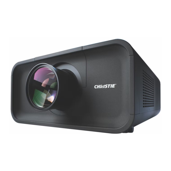
- Page 1 LX700 U S E R M A N U A L 020-000119-01...
-
Page 2: Features And Design
Features and Design This Multimedia Projector is designed with most advanced technology for portability, durability, and ease of use. This projector utilizes built-in multimedia features, a palette of 1.07 billion colors, and matrix liquid crystal display (LCD) technology. Functionally Rich Multilanguage Menu Display This projector has many useful functions such Operation menu is available in 12 languages;... -
Page 3: Table Of Contents
Table of Contents Features and Design....2 Computer Input ....38 Computer System Selection Table of Contents . -
Page 4: To The Owner
To The Owner Safety Precaution Before installing and operating the projector, read this manual thoroughly. The projector provides many convenient features and WARNING: THIS APPARATUS MUST BE EARTHED. functions. Operating the projector properly enables TO REDUCE THE RISK OF FIRE OR you to manage those features and maintains it in good ELECTRIC SHOCK, DO NOT EXPOSE THIS condition for many years to come. -
Page 5: Safety Instructions
Safety Instructions This projector should be operated only from the type of power All the safety and operating instructions should be read before source indicated on the marking label. If you are not sure of the product is operated. the type of power supplied, consult your authorized dealer or local power company. -
Page 6: Air Circulation
Safety Instructions Air Circulation Openings in the cabinet are provided for ventilation. IMPORTANT! To ensure reliable operation of the product and to protect it from overheating, these openings must not Filter Maintenance!! be blocked or covered. The projector uses a lamp which generates significant heat. -
Page 7: Installing The Projector In Proper Directions
Safety Instructions Installing the Projector in Proper Directions Use the projector properly in specified positions. Improper positioning may reduce the lamp life and result in severe accident or fire hazard. This projector can project the picture in upward, downward, or inclined position in perpendicular direction to the horizontal plane. -
Page 8: Moving The Projector
Safety Instructions Moving the Projector Use the handle grip when moving the projector. Retract the adjustable feet to prevent damage to the lens and cabinet when carrying. When this projector is not in use for an extended period, put it into a suitable case to protect the projector. CAUTION IN CARRYING OR TRANSPORTING THE PROJECTOR –... -
Page 9: Compliance
: LX700 Trade Name ....: Christie Responsible party ..: CHRISTIE DIGITAL SYSTEMS, Inc. Address ..... : 10550 Camden Drive Cypress, CA 90630 U.S.A. AC Power Cord Requirement The AC Power Cord supplied with this projector meets the requirement for use in the country you purchased it. -
Page 10: Part Names And Functions
Part Names and Functions Indicators Front Top Cover Top Cover Release Button Infrared Remote Receiver (Front) Projection Lens (optional) Light-Block Sheet Adjustable Feet Air Intake Vent Filter Cover Lamp Cover Exhaust Vent CAUTION Hot air is exhausted from the exhaust vent. -
Page 11: Rear Terminal
Part Names and Functions Rear Terminal USB CONNECTOR (Series B) COMPUTER INPUT TERMINAL (DIGITAL) Connect the computer output digital signal to this Use this connector when controlling a computer with the remote control of the projector. Connect terminal. The HDTV (HDCP compatible) signal can the USB terminal of your computer to this also be connected (pp.22-23). -
Page 12: Rear Terminal
Part Names and Functions Rear Terminal MONITOR OUT TERMINAL This terminal can be used to output the incoming analog RGB signal from INPUT 1-3 terminal to the other monitor (pp.22-23). AUDIO MONITOR OUTPUT JACK This jack outputs the audio signal from computer or video equipment to external audio equipment (p.24). -
Page 13: Side Control And Indicators
Part Names and Functions Side Control and Indicators Side Control Indicators (on the top panel) ON/STAND-BY button POWER indicator Turn the projector on or off (pp.26–27). – Light when in stand-by mode and during operations. INPUT button – Blink in the Power management mode (p.56). Select an input source (pp.35–37). -
Page 14: Remote Control
Part Names and Functions Remote Control STAND-BY button MOUSE POINTER button Turn the projector off (p.27). Move a pointer of the projector or a pointer for wireless mouse operation (p.34). WIRED REMOTE jack Connect the remote control cable (not supplied) to SELECT button this jack when using as a wired remote control. - Page 15 Part Names and Functions Remote Control For PIN code and remote control code. FREEZE button D.ZOOM button Select the Digital zoom +/- mode and resize the Freeze the picture on the screen (p.33). image (p.44). P-TIMER button INPUT 1 – 3 buttons Operate the P-timer function (p.33).
-
Page 16: Remote Control Battery Installation
Part Names and Functions Remote Control Battery Installation Open the battery Install new batteries into Replace the compartment lid. the compartment. compartment lid. Press the lid downward and Two AAA size batteries slide it. For correct polarity (+ and –), be sure battery terminals are in contact with pins in the compartment. -
Page 17: Remote Control Code
Part Names and Functions Remote Control Code The eight different remote control codes (Code 1–Code 8) are assigned to this projector. Switching the remote control codes prevents interference from other remote controls when several projectors or video equipment next to each other are operated at the same time. Change the remote control code for the projector first before changing that for the remote control. -
Page 18: Installation
Installation Adjustable Feet Projection angle can be adjusted up to 6.5 degrees with the adjustable feet. Rotate the adjustable feet and tilt the projector to the proper height; to raise the projector, rotate the both feet clockwise. To lower the projector or to retract the adjustable feet, rotate the both feet counterclockwise. -
Page 19: Lens Installation
Installation Lens Installation When replacing the lens or using an optional lens, install the lens by following the instructions below. Ask the sales dealer for detailed information of the optional lens specifications. Top cover release button Removing the lens Top cover Shift the lens to the center position by using the Lens shift function (p. - Page 20 Installation Attaching the lens to the projector Turn off the projector and unplug the AC power cord. Fit the lens to the projector. Make sure that the lens is fully inserted to the projector. Push the Lens Lock Lever downward. Make sure that the lens is properly locked.
- Page 21 Installation Focus correction Focus adjustment Lens: 38-809049-51 When the lens is attached to the projector and images (0.8:1 fixed lens) are being projected onto the screen, the peripheral focus may be out of focus in some localized areas. If Set up the projector and project image on the screen. this happens, insert the one, of three sizes of spacers, 1.
-
Page 22: Connecting To A Computer (Digital And Analog Rgb)
Installation Connecting to a Computer (Digital and Analog RGB) Cables used for connection ( = Cables not supplied with this projector.) USB port Monitor Output Monitor Output Monitor Output Monitor Input Serial out DVI-Digital Serial Cross cable cable cable cable cable cable G B R H/V V... -
Page 23: Connecting To Video Equipment (Video, S-Video)
Installation Connecting to Video Equipment (Video, S-Video) Cables used for connection ( = Cables not supplied with this projector.) Monitor Out Signal Table Input Terminal Monitor Out Cable RGB (PC analog) D-sub15 RGB (SCART) Input 1 RGB (PC digital) DVI-D RGB (AV HDCP) A cable with one Video... -
Page 24: Connecting For Audio Signal
Installation Connecting for Audio Signal Cables used for connection ( = Cables not supplied with this projector.) Audio Output Audio Output External Audio Equipment Audio Input Audio Audio cable cable (stereo) (stereo) Audio cable AUDIO IN / AUDIO IN / (stereo) AUDIO OUT (stereo) -
Page 25: Connecting The Ac Power Cord
Installation Connecting the AC Power Cord This projector uses nominal input voltages of 100–120 V or 200– 240 V AC and it automatically selects the correct input voltage. It is designed to work with single-phase power systems having a grounded neutral conductor. To reduce the risk of electrical shock, do not plug into any other type of power system. -
Page 26: Basic Operation
Basic Operation Turning On the Projector Complete peripheral connections (with a computer, VCR, etc.) before turning on the projector. Connect the projector’s AC power cord into an AC outlet. The LAMP/SHUTTER indicator lights red and the POWER indicator lights green. Press the ON/STAND-BY button on the side control The preparation display will disappear after 30 or the ON button on the remote control. -
Page 27: Turning Off The Projector
Basic Operation Turning Off the Projector Press the ON/STAND-BY button on the side control or the STAND-BY button on the remote control, and “Power off?” appears on the screen. Press the ON/STAND-BY button on the side control or the STAND-BY button on the remote control again to turn off the projector. -
Page 28: How To Operate The On-Screen Menu
Basic Operation How to Operate the On-Screen Menu The projector can be adjusted or set via the On-Screen Side Control Menu. For each adjustment and setting procedure, refer to the respective sections in this manual. MENU button Press the MENU button on the side control or the SELECT button remote control to display the On-Screen Menu. -
Page 29: Menu Bar
Basic Operation Menu Bar For detailed functions of each menu, see “Menu Tree” on pages 72-74. For Computer Source Guide Window Image Adjust Menu Show the selected Menu of the On-Screen Menu. Used to adjust the computer image. [Contrast/ Brightness/ Color management/Auto picture control/Advanced Input Menu color/Color temp./White balance (R/G/B)/Offset (R/G/B)/... -
Page 30: Operating With Projector Control
Basic Operation Operating with Projector Control Lens Operation Side Control The following lens operation can be made with the Lens button on the side control. LENS button Press the LENS button to enter each lens operation mode. The selected adjustment display appears on the screen. Zoom Focus Lens Shift... -
Page 31: Sound Adjustment
Basic Operation Sound Adjustment Direct Operation Side Control Volume Press the VOLUME+/– buttons on the side control or on the VOLUME +/– buttons remote control to adjust the volume of Audio Output. The volume dialog box appears on the screen for a few seconds. Mute Press the MUTE button on the remote control to temporarily turn off the AUDIO OUT. -
Page 32: Operating With Remote Control
Basic Operation Operating with Remote Control Using the remote control for some frequently used operations is advisable. Just pressing one of the buttons enables you to make the desired operation quickly without calling up the On-Screen Menu. AUTO PC button Remote Control Press the AUTO PC button on the remote control to operate the Auto PC Adj. - Page 33 Basic Operation Remote Control MOUSE POINTER button Move the pointer on the screen with this button. POINTER button Press POINTER button on the remote control to display the Pointer on the screen. MOUSE P-TIMER button POINTER Press the P-TIMER button on the remote control. The Timer button display “00 : 00”...
-
Page 34: Pointer Function
Basic Operation Pointer Function You can move the Pointer of the projector with the remote control to emphasize a part of the projected image. Press the POINTER button to activate the Pointer function. MOUSE POINTER button Use the MOUSE POINTER button to move the Pointer. To cancel the Pointer function, press the POINTER button again or press any other button. -
Page 35: Input Selection
Input Selection Input Side Control/Remote control button Side Control Remote Control operation INPUT button INPUT button Input 1 INPUT button Input 2 Input 3 Side Control/Remote control Operation Press the INPUT button on the side control or the remote control. It switches to INPUT 1, INPUT 2, and INPUT 3 as you press the INPUT button. -
Page 36: Computer Input Source Selection
Input Selection Computer Input Source Selection Menu Operation WHEN SELECTING INPUT 1 (COMPUTER INPUT TERMINALS ) Press the MENU button to display the On-Screen Menu. Use INPUT MENU the Point buttons to move the red frame pointer to the INPUT Menu icon. Input Menu icon Use the Point buttons to move the red arrow pointer... -
Page 37: Video Input Source Selection
Input Selection Video Input Source Selection Menu Operation WHEN SELECTING INPUT 1 (COMPUTER INPUT TERMINALS ) INPUT MENU When connecting to video equipment, select the type of Video source in the Source Select Menu. Input Menu icon RGB (Scart) When scart video equipment is connected to the INPUT 1 Move the pointer (red arrow) to Input (ANALOG) terminal, select RGB (Scart). -
Page 38: Computer Input
Computer Input Computer System Selection Automatic Multi-Scan System This projector automatically tunes to various types of computers based on VGA, SVGA, XGA, SXGA, SXGA+, WXGA, UXGA or WUXGA (refer to “Compatible Computer Specifications” on pages 78–79). If a computer is selected as a signal source, this projector automatically detects the signal format and tunes to project a proper image without any additional settings. -
Page 39: Auto Pc Adjustment
Computer Input Auto PC Adjustment Auto PC Adjustment function is provided to automatically adjust Fine sync, Total dots, Horizontal and Vertical positions to conform to your computer. Direct Operation Remote Control The Auto PC adjustment function can be operated directly by pressing the AUTO PC button on the remote control. -
Page 40: Manual Pc Adjustment
Computer Input Manual PC Adjustment Some computers employ special signal formats which may not be tuned by Multi-Scan system of this projector. Manual PC Adjustment enables you to precisely adjust several parameters to match those special signal formats. The projector has 10 independent memory areas to store those parameters manually adjusted. It allows you to recall the setting for a specific computer. - Page 41 Computer Input Reset To reset the adjusted data, select Reset and press the SELECT button. A confirmation box appears and then select [Yes]. All adjustments will return to their previous figures. Mode free To clear the adjusted data. To clear the adjusted data, select Mode free and then press the SELECT button.
-
Page 42: Image Level Selection
Computer Input Image Level Selection Menu Operation Press the MENU button to display the On-Screen Menu. Use IMAGE SELECT MENU the Point buttons to move the red frame pointer to the Image Select Menu icon. Use the Point buttons to move the red frame pointer to Image Select Menu icon the desired image level and then press the SELECT button. -
Page 43: Screen Size Adjustment
Computer Input Screen Size Adjustment Select the desired screen size that conforms to the input signal source. Press the MENU button to display the On-Screen Menu. Use SCREEN MENU the Point buttons to move the red frame pointer to the Screen Menu icon. - Page 44 Computer Input Keystone SCREEN MENU This function is used to store or reset the keystone correction when the AC power cord is unplugged. Use the Point buttons to switch between each option. Store. . . Keep the keystone correction even when the AC power cord is unplugged.
-
Page 45: Video Input
Video Input Video System Selection Press the MENU button to display the On-Screen Menu. Use the Point buttons to move the red frame pointer to the AV System Menu icon. Use the Point buttons to move the red arrow pointer to the desired system and then press the SELECT button. -
Page 46: Image Level Selection
Video Input Image Level Selection Menu Operation Press the MENU button to display the On-Screen Menu. Use IMAGE SELECT MENU the Point buttons to move the red frame pointer to the Image Select Menu icon. Use the Point buttons to move the red frame pointer to Image Select Menu icon the desired image level and then press the SELECT button. -
Page 47: Screen Size Adjustment
Video Input Screen Size Adjustment Press the MENU button to display the On-Screen Menu. Use SCREEN MENU the Point buttons to move the red frame pointer to the Screen Menu icon. Use the Point buttons to move the red frame pointer to Screen Menu icon the desired function and then press the SELECT button. - Page 48 Video Input Keystone SCREEN MENU This function is used to store or reset the keystone correction when the AC power cord is unplugged. Use the Point buttons to switch between each option. Store. . . Keep the keystone correction even when the AC power cord is unplugged.
-
Page 49: Picture Image
Picture Image Image Adjustment Press the MENU button to display the On-Screen Menu. Use IMAGE ADJUST MENU the Point buttons to move the red frame pointer to the Image Adjust Menu icon. Use the Point buttons to move the red frame pointer to Image Adjust Menu icon the desired item and then press the SELECT button to display the adjustment dialog box. - Page 50 Picture Image COLOR SELECTION MODE (continued) COLOR SELECTION MODE COLOR M. Level and phase Gamma Return to the COLOR MANAGEMENT POINTER. (If you press adjustment palette. adjustment palette. the MENU button on the side control or the remote control, it returns to the COLOR MANAGEMENT POINTER and you will need to reselect and readjust the color.) MENU...
- Page 51 Picture Image White balance (Red/Green/Blue) Press the Point button to lighten red/green/blue tone; press the Point button to deepen red/green/blue tone (from 0 to 63). Offset (Red/Green/Blue) Press the Point button to lighten red/green/blue tone of the black level of an image; press the Point button to deepen red/green/ blue tone of the black level of an image (from 0 to 63).
-
Page 52: Setting
Setting Setting This projector has a Setting menu that allows you to set up other various functions. Press the MENU button to display the On-Screen Menu. Use the Point buttons to move the red frame pointer to the SETTING MENU (Language) Setting Menu icon. - Page 53 Setting Background The selected background screen will be displayed when no input Note: signal is detected. Blue . . . Blue colored background. User . . . The image you captured. Black. . . Black colored background. Logo This function allows you to customize the screen logo with Logo Logo select, Capture, and Logo PIN code lock functions.
- Page 54 Setting Logo PIN code lock Logo PIN Code Lock This function prevents an unauthorized person from changing the screen logo. Off ..The screen logo can be changed freely from the Logo Menu. On ..The screen logo cannot be changed without a Logo PIN code.
- Page 55 Setting Lamp control This function allows you to change the brightness of the screen. Auto ..Brightness according to the input signal. Normal . . . Normal brightness. Eco 1..Lower brightness and Fan control set to Normal. Lower brightness reduces the lamp power consumption and extends the lamp life.
- Page 56 Setting RC sensor Select a location of the infrared remote receiver of the remote control. See “Remote Control Receivers and Operating Range” on page 16 for details. Both ..Activate both the front and back receiver. Front ..Activate only the front receiver. Back ..
- Page 57 Setting Security Security Key lock This function locks the side control and remote control buttons to prevent operation by unauthorized persons..Unlocked..Lock the side control buttons. To unlock, use the remote control. .
- Page 58 Setting Enter a PIN code Use the Point buttons on the side control or Number buttons on the remote control to enter a number. When using side control Enter a PIN code Use the Point buttons on the side control to select a number. Press the Point button to fix the number and move the red frame pointer to the next box.
- Page 59 Setting Shutter Shutter function is available to block out light to the screen, so that the screen can be used for the other presenters. Protection Prohibit the shutter operation from the remote control and the projector's side control. Remote control Selecting "On"...
- Page 60 Setting Filter counter Filter counter This function is used to set a frequency for the filter replacement. Use the Point buttons to move the red frame pointer to Filter counter and then press the SELECT button. A dialog box appears showing the Used time option and the Scrolls remaining option.
-
Page 61: Maintenance And Care
Maintenance and Care Filter Instructions Filter prevents dust from accumulating on the optical elements inside the projector. Should the filter becomes clogged with dust particles, it will reduce cooling fans’ effectiveness and may result in internal heat buildup and adversely affect the life of the projector. This projector has an electrically operated filter which helps you to replace the filter easily. -
Page 62: Replacing The Filter Cartridge
ORDER REPLACEMENT FILTER CARTRIDGE Replacement filter cartridge can be ordered through your dealer. When ordering, give the following information to the dealer. Model No. of your projector LX700 Replacement Filter Cartridge Type No. 003-001726-01 (Service Parts No. 610 334 3747) User's Manual Rev. -
Page 63: Resetting The Filter Counter
Maintenance and Care Resetting the Filter Counter Filter counter Be sure to reset the Filter counter after replacing the filter cartridge. Press the MENU button to display the On-Screen Menu. Use the Point buttons to move the red frame pointer to the Setting Menu icon. -
Page 64: Lamp Replacement
Maintenance and Care Lamp Replacement When the projection lamp of the projector reaches its end of life, the Lamp replacement icon appears on the screen and LAMP REPLACE indicator lights orange. Replace the lamp with a new one promptly. The timing when the LAMP REPLACE indicator should light is depending on the lamp mode. -
Page 65: Resetting The Lamp Counter
ORDER REPLACEMENT LAMP Replacement lamp can be ordered through your dealer. When ordering, give the following information to the dealer. Model No. of your projector LX700 Replacement Lamp Type No. 003-120458-01 (Service Parts No. 610 341 1941) User's Manual 020-000119-01 Rev. -
Page 66: Lamp Handling Precautions
Maintenance and Care LAMP HANDLING PRECAUTIONS This projector uses a high-pressure lamp which must be handled carefully and properly. Improper handling may result in accidents, injury, or create a fire hazard. Lamp lifetime may differ from lamp to lamp and according to the environment of use. There is no guarantee of the same lifetime for each lamp. -
Page 67: Cleaning The Projection Lens
Maintenance and Care Cleaning the Projection Lens Unplug the AC power cord before cleaning. Gently wipe the projection lens with a cleaning cloth that contains a small amount of non-abrasive camera lens cleaner, or use a lens cleaning paper or commercially available air blower to clean the lens. -
Page 68: Warning Indicators
Maintenance and Care Warning Indicators The WARNING indicators show the state of the function which protects the projector. Check the state of the WARNING indicators and the POWER indicator to take proper maintenance. The projector is shut down and the WARNING TEMP. Top Panel indicator is blinking red. -
Page 69: Appendix
Appendix Troubleshooting Before calling your dealer or service center for assistance, check the items below once again. 1. Make sure you have properly connected the projector to peripheral equipment as described on pages 22–24. 2. Check the cable connection. Make sure that all computers, video equipment, and power cords are properly connected. - Page 70 Appendix – Filter is out of scroll. Replace the filter cartridge with a new one promptly. (See pages 62 -63) appears on the screen – Adjust the focus of the projector. – Check Projection Lens to see if it needs cleaning. Note: Moving the projector from a cool temperature location to a warm temperature location may result in moisture condensation on Projection Lens.
- Page 71 Appendix – Power management function runs by initial setting. Check “SETTING” section on page – When the filter cartridge replacement icon keeps appearing on the screen at turning on the projector for some time and no action is taken to replace the filter cartridge, the The power is turned off projector will be automatically shut down in 3 minutes after turning on to protect the automatically.
-
Page 72: Menu Tree
Appendix Menu Tree Computer Input/Video Input Input Input 1 RGB (PC analog) Go to System RGB (Scart) RGB (PC digital) Go to System RGB (AV HDCP) Input 2 Video Go to System Y, Pb/Cb,Pr/Cr Go to System Go to System Input 3 Video Go to System... - Page 73 Appendix Computer Input System Image Select Mode 1 Standard Mode 2 Real SVGA 1 Image 1 SVGA 2 SVGA 3 Image 10 System displayed in the System Menu varies depending on the input signal. PC Adjust Screen Auto PC adj. Normal Fine sync.
- Page 74 Appendix Computer Input/Video Input Setting Language 12 languages provided. Quit Menu Position/Simple Menu Display On/Countdown Off/Off Background Blue/User/Black User/Default/Off Logo Logo select Yes/No Capture Logo PIN code lock On/Off Logo PIN code change Quit Quit Lamp control Auto/Normal/Eco 1/Eco 2 Filter control Yes/No Fan control...
-
Page 75: Indicators And Projector Condition
Appendix Indicators and Projector Condition Check the indicators for the projector condition. The projector is operating normally. Indicators Projector Condition LAMP/ WARNING WARNING LAMP POWER SHUTTER TEMP . FILTER REPLACE green red/blue orange orange The projector is off. (The AC power cord is unplugged.) The projector is in stand-by mode. - Page 76 Appendix The projector is detecting abnormal condition. Indicators Projector Condition WARNING WARNING LAMP LAMP/ POWER SHUTTER TEMP . FILTER REPLACE green red/blue orange orange The temperature inside the projector is elevated close to the abnormally high level. The temperature inside the projector is abnormally high. The projector cannot be turned on.
- Page 77 Appendix The projector is detecting abnormal condition. Indicators Projector Condition WARNING WARNING LAMP LAMP/ POWER SHUTTER TEMP . FILTER REPLACE green red/blue orange orange If the Filter counter reached a time set in the timer setting, a Filter replacement icon (Fig.2) appears on the screen and the WARNING FILTER indicator on the top panel lights up.
-
Page 78: Compatible Computer Specifications
Appendix Compatible Computer Specifications Basically this projector can accept the signal from all computers with the V- and H-Frequency mentioned below and less than 180 MHz of Dot Clock. ON-SCREEN RESOLUTION H-Freq. V-Freq.(Hz) ON-SCREEN RESOLUTION H-Freq. V-Freq.(Hz) DISPLAY (kHz) DISPLAY (kHz) VGA 1 640x480... - Page 79 Appendix When an input signal is digital from the DVI terminal, refer to the chart below. ON-SCREEN RESOLUTION H-Freq. V-Freq.(Hz) ON-SCREEN RESOLUTION H-Freq. V-Freq.(Hz) DISPLAY (kHz) DISPLAY (kHz) D-VGA 640x480 31.470 59.940 D-WXGA 11 1280x800 49.702 59.810 D-480p 720x480 31.470 59.880 D-SXGA 2 1280x1024...
-
Page 80: Technical Specifications
Appendix Technical Specifications Mechanical Information Projector Type Multi-media Projector Dimensions (W x H x D) 14.56” x 7 .36” x 17 .32” (370.0 mm x 187 .0 mm x 439.9 mm) Net Weight 25.1 lbs (11.4 kg) Feet Adjustment 0˚ to 6.5˚ Panel Resolution LCD Panel System 1.3”... -
Page 81: Optional Parts
Appendix Optional Parts The parts listed below are optionally available. When ordering those parts, specify the item name and Model No. to the sales dealer. Model No. Standard Zoom Lens : 38-809051-XX Long Zoom Lens : 38-809048-01 Ultra Long Zoom Lens : 38-809068-01 Short Zoom Lens : 38-809047-01... -
Page 82: Configurations Of Terminals
Appendix Configurations of Terminals ANALOG/ MONITOR OUT (Mini D-sub 15 pin) Input Red Input +5V Power Green Input Ground (Vert.sync.) Blue Input Ground No Connect DDC Data Ground (Horiz.sync.) Horiz. sync. Input (Composite H/V sync.) Ground (Red) Vert. sync. Input Ground (Green) DDC Clock Ground (Blue) -
Page 83: Pin Code Number Memo
Appendix PIN Code Number Memo Write down the PIN code number in the column below and keep it with this manual securely. If you forgot or lost the number and unable to operate the projector, contact the service station. PIN Code Lock No. Factory default set No: 1 2 3 4* Logo PIN Code Lock No. -
Page 84: Dimensions
Appendix Dimensions Unit: inch (mm) 14.57 (370) 4.33 (110) 4.33 (110) 6.5º MAX 5.75 (146) 5.20 (132) 4.13 (105) Screw Holes for Ceiling Mount Screw: M6 Depth: 0.393 (10.0) User's Manual Rev. 1 (11/08) 020-000119-01... - Page 86 Americas Canada Chile Christie Digital Systems USA, Inc. Christie Digital Systems Canada, Inc. Representative Office 10550 Camden Drive 809 Wellington St. N. Christie Digital Systems USA, Inc. Cypress CA 90630 Kitchener, Ontario N2G 4Y7 Av. Pedro Fontova 7619 of 60...
Need help?
Do you have a question about the LX700 and is the answer not in the manual?
Questions and answers