
Related Manuals for CalAmp 819-GPRS series


Summary of Contents for CalAmp 819-GPRS series
- Page 1 G S M G P R S S e r i a l C e l l u l a r D a t a M o d e m User Manual 001-0003-829 Revision 1; February 2008...
- Page 2 REVISION HISTORY Released February 2008...
-
Page 3: Table Of Contents
TABLE OF CONTENTS SECTION 1 – PREFACE ......................5 SECTION 1 – PREFACE Copyright Notice......................5 Modem Use........................5 Interference Issues ......................5 Mobile Application Safety ....................6 SECTION 2 – PRODUCT OVERVIEW SECTION 2 – PRODUCT OVERVIEW ..................7 Module Identification....................... - Page 4 TABLE OF CONTENTS Network Service Commands................... 47 Internal Internet Service Commands ................50 Step-by-step instructions on how to configure and use TCP/IP communications:....50 Maximum number of profiles defined / used:..............50 GPRS Commands......................52 Short Message Service (SMS) Commands ................ 55 SIM Related Commands....................
-
Page 5: Section 1 - Preface
Specifications described are typical only and are subject to normal manufacturing and service tolerances. CalAmp reserves the right to modify the equipment, its specification or this manual without prior notice, in the interest of improving performance, reliability or servicing. At the time of publication all data is correct for the operation of the equipment at the voltage and/or temperature referred to. -
Page 6: Mobile Application Safety
Road safety is crucial. Observe National Regulations for cellular telephones and devices in vehicles. • Avoid potential interference with vehicle electronics by correctly installing the 819-GPRS. CalAmp DataCom recommends installation by a professional. 001-0003-829 Revision 1 Page 6 of 65... -
Page 7: Section 2 - Product Overview
IMEI Dec: The International Mobile Equipment Identifier of the cellular module in decimal format. General Description The 819-GPRS Cellular Data Modem from CalAmp is the ideal solution for a wide range of cellular data network serial connectivity requirements. The 819-GPRS version features GSM GPRS speeds. The 819-GPRS supports both circuit- switched and packet-switched services. -
Page 8: External Connections
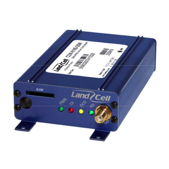
External Connections Front panel connections Fig. 2.1 819-GPRS Front Panel 819-GPRS front panel indicators include: PWR: Green LED indicating power to unit. Tx: Red LED indicating Transmit activity. DCD: Amber LED indicating Data Carrier Detect from cellular network. Rx: Green LED indicating Receive activity. RF (antenna): SMA female, primary antenna connection. -
Page 9: Rs-232 Serial Port Integration Parameters
RS-232 Serial Port Integration Parameters Table 2.1 provides the serial cable design information to integrate the 819-GPRS into your system. Table 2.1 Standard RS-232 DE-9 Pin out Name Direction Description «— Carrier Detect «— Receive Data —» Transmit Data —» Data Terminal Ready System Ground «—... -
Page 10: Section 3 - Getting Started
Information Card Setting up the 819-GPRS Modem using the GPRS 819S Driver: You may download all necessary modem driver files from our website at http://www.calamp.com. If you are installing the modem using the drivers from the website, refer to these steps: 1. - Page 11 2. Select the “Modem” tab. Select “Add...” and follow the Wizard. Check “Don’t Detect My Modem”. 001-0003-829 Revision 1 Page 11 of 65...
- Page 12 3. Select "Have Disk…" Click “Next”. 4. Browse to the file location where the GPRS 819S modem driver was downloaded. 001-0003-829 Revision 1 Page 12 of 65...
- Page 13 5. Select the Siemens AG. manufacturer and MC75 Modem (GPRS) model then click “Next”. 6. Assign the modem to the COM port connected to the modem. Click “Next”. 7. Click “Finish”. 001-0003-829 Revision 1 Page 13 of 65...
-
Page 14: Setting Up The 819-Gprs Using Native Windows Drivers
Setting up the 819-GPRS using native Windows drivers: 1. Click on Start --> Settings --> Control Panel. Select "Phone and Modem Options". 2. Select the “Modem” tab. Select “Add...” and follow the Wizard. Check “Don’t Detect My Modem”. 3. Select "Standard 19200 bps Modem." Click “Next”. 4. - Page 15 2. From the Network Connections screen, select “Create a new connection”. Follow the Wizard as it goes through the steps to create a dial-up connection by selecting “Next”. 3. For the connection type, select “Connect to the Internet”, then click “Next”. 001-0003-829 Revision 1 Page 15 of 65...
- Page 16 4. Select “Set up my connection manually”, then click “Next”. 5. For the internet connection, select “Connect using a dial-up modem”, then click “Next”. 001-0003-829 Revision 1 Page 16 of 65...
- Page 17 6. Check the box by the Modem for the GPRS device, then click “Next”. 7. Type in a connection name, then click “Next”. 001-0003-829 Revision 1 Page 17 of 65...
- Page 18 8. Type in *99***1# for the phone number to dial, this is the number for GPRS packet data calls. 9. Typically the username and password are left blank. Click “Next” 10. Finish off the Wizard. The network connection should now be available on the Network Connections screen.
- Page 19 From the Properties window, confirm that the correct modem driver is checked under “Connect using:” and select Configure... 001-0003-829 Revision 1 Page 19 of 65...
- Page 20 In the Configuration window, confirm that the Maximum speed (bps) is set to 115200, as shown below. Click OK to exit out of each screen. Refer to Packet Data Call Setup in Section 4 for further information on call setup procedures. 001-0003-829 Revision 1 Page 20 of 65...
-
Page 21: Operational States
Operational States The modem has three operational states: • Command State • Online State • Online Command State When first powered on, the modem is in the Command State where it is able to accept AT commands. When instructed to dial out or to answer a data call, the phone is in the Online State. Activating your Modem 1. - Page 22 6. Verify good signal strength with the AT+CSQ command. A typical reply is +CSQ 26, 0. The first number is signal strength and ranges from 0 to 31 (the higher the number, the stronger the signal.) 7. Confirm your SIM card is properly installed with the AT^SCID command. A reply of ^SCID:<20 digit CID number>...
-
Page 23: Section 4 - Call Setup Information
– – Circuit Switch Data (CSD) Call Setup Steps 1. Connect the modem to an active COM port on a PC with an RS-232 9 pin straight through cable. 2. Insert the SIM card into the unit. Be sure your account can support CSD calls. 3. -
Page 24: Packet Data Call Setup Steps
19. The terminal window connected to the 819-GPRS modem, will say “RING” and then once the modems have negotiated a connection it should say “CONNECT 9600/RPL” for a 9600 baud connection. 20. You can now type in text in either terminal window and it will appear in the other terminal window. -
Page 25: Gprs Internet Connection Set Up
14. Set the username and password as defined for your carrier (usually blank). 15. Enter the phone number as *99***1# with no area code and click on Dial. 16. The modem will dial out and attempt to connect. 17. If the configured baud rate for the modem, the COM port, the modem and the DUN do not match, the DUN will not be able to talk to the modem properly and you will get a hardware error message. -
Page 26: Internet Service Information: Http Receive Data
Start the ping test using the AT^SISX command. The example pings google.com 4 times with a timeout of 2000 ms. AT^SISX="Ping",0,"google.com",4,2000 The response output example is shown below (the output may differ, but should show a successful ping response); ^SISX: "Ping",1,0,"64.233.187.99",798 ^SISX: "Ping",1,0,"64.233.187.99",526 ^SISX: "Ping",1,0,"64.233.187.99",475 ^SISX: "Ping",1,0,"64.233.187.99",471... -
Page 27: Internet Service Information: Http Send Data
Open the connection by typing AT^SISO=0. A response should display showing that the connection was successful, as shown below; ^SIS: 0, 3, 2201, "HTTP Response:HTTP/1.1 200 OK" ^SISR: 0, 1 The ^SISR: 0, 1 response indicates that there is data available and can be read by sending the AT^SISR command. -
Page 28: Tcp Client Socket Setup
Send the data (if size > 128 bytes) by typing AT^SISW=0,<size> Enter the data to be sent, you will get OK when all the bytes are transmitted. A response will be sent something like: ^SIS: 0, 0, 2201, "HTTP/1.1 200 OK" ^SISR: 0, 1 Read the HTTP Answer by typing the command, AT^SISR=0,1500. -
Page 29: Tcp Socket Server Setup
TCP Socket Server Setup This example describes commands to setup the modem as a TCP Socket Server. Configure the modem using the following AT commands: AT^SISS=0,alphabet,1 AT^SISS=0,srvtype,socket AT^SISS=0,address,"socktcp://listener:2000" AT^SISS=0,conid,0 Open the connection by typing, AT^SISO=0. Close connection by typing, AT^SISC=0. UDP Client Socket Setup This example describes commands to setup the modem as a UDP Socket Client. -
Page 30: Pop3 Generic Settings
POP3 Generic Settings This example describes commands to setup the modem as a POP3 Server. Configure the modem using the following AT commands: AT^SISS=0,srvtype,pop3 AT^SISS=0,user,<USER> AT^SISS=0,passwd,<PASSWORD> AT^SISS=0,address,<POP3 server IP address> AT^SISS=0,pcmd,1 (this is the Status Command) AT^SISS=0,conid,0 Open the connection by typing, AT^SISO=0. Close connection by typing, AT^SISC=0. -
Page 31: Ftp Upload (Put) Setup
FTP Upload (PUT) Setup This example describes commands to setup the modem to upload to an FTP server. The module will support only passive mode for FTP transfers. Configure the modem using the following AT commands: AT^SISS=0,srvType,ftp AT^SISS=0,conId,0 AT^SISS=0,address,"ftpput://myname:mypasswd@192.168.1.2/upload/example.bin;type=i" The file “example.bin” will be created on the FTP server at IP 192.168.1.2. Open the connection by typing, AT^SISO=0. -
Page 32: Section 5 - Sim Card Specific Information
– – The AT+CPIN command controls network authentication of the TC65. The read command (AT+CPIN?) returns an alphanumeric string indicating whether or not network authentication is required. The write command allows the modem to store the entered password. This may be for example the SIM PIN1 to register to the GSM network, or the SIM PUK1 to replace a disabled SIM PIN1 with a new one, or the PH-SIM PIN if the client has taken precautions for preventing damage in the event of loss or theft etc. -
Page 33: What To Do If Pin Or Password Authentication Fails
What to do if PIN or password authentication fails? PIN1 / PUK1: After three failures to enter PIN 1, the SIM card is blocked (except for emergency calls). +CME ERROR: 12 will prompt the client to unblock the SIM card by entering the associated PUK (= PIN Unblocking Key / Personal Unblocking Key). -
Page 34: Section 6 - Troubleshooting
– – In this section, you will find important information relating to the setup and diagnosis of your 819- GPRS modem. If you are having trouble communicating with the modem, please read this "Troubleshooting" section in full. If, after reviewing this section, you are still having problems connecting, call our Technical Support line at: 507-833-8819 for more assistance. - Page 35 To test the link between your modem and the cellular network try to call your cell phone. Type in: ATD<phone number to call>; (for example ATD15075551234;) and press enter. This command will perform a voice call similar to the type a standard home phone would make and if your modem has been activated correctly your cell phone should ring and display the number of the modem.
-
Page 36: Section 7 - Profiles
– – In addition to the default profile, you can store an individual one with AT&W. To alternate between the two profiles enter either ATZ (loads user profile) or AT&F (restores factory profile). NOTE: Every ongoing or incoming call will be terminated. Table 7.1: Profile Commands Returns the current parameter setting. -
Page 37: Section 8 - Common At Command Reference Guide
– – Below you will find a reference guide of the AT commands most commonly used in day-to-day operation of the modem. Table 8.1: Common AT Commands Command Description Configuration Commands AT&F Set all current parameters to manufacturer defaults AT&V Display current configuration AT&W Stores current configuration to user defined profile... - Page 38 Network Service Commands Signal Quality AT+CSQ Example response; +CSQ: 25,0 has an RSSI of -63 dBm Cell Info Table Example response: GPRS Monitor BCCH G PBCCH PAT MCC MNC NOM TA RAC # Cell # 0637 1 - 234 05 00 0B BCCH - ARFCN of BCCH carrier G - GPRS status:...
-
Page 39: Section 9 - At Command Reference
– – All modem functions are controlled using the same industry-standard AT commands that are used to control landline modems. A knowledge of all these commands is not required by most users, but are provided here as a reference. AT Command Types There are several types of AT commands as defined in the following list;... -
Page 40: Result Codes
Result Codes After issuing a command, a result code will typically be displayed on the screen to inform you if the command was successful, unsuccessful, improperly formatted, etc. When in the command mode, thirteen possible result codes may be returned. The result codes can be set to display as either digits or words by accessing the Verbose command, ATV. - Page 41 2 - CONNECT <text> result code returned, dial tone detection is enabled, busy detection is disabled. 3 - CONNECT <text> result code returned, dial tone detection is disabled, busy detection is enabled. 4 - CONNECT <text> result code returned, dial tone and busy detection are both enabled.
-
Page 42: Status Control Commands
Status Control Commands The AT Commands described in this section allow the external application to obtain various status information from the modems cellular module. Table 9.4: Status Control Commands Command Description Mobile Equipment Event Reporting: AT+CMER=<mode>,0,0,<ind>,0 Mode: 0 - Discard "+CIEV" and "^SLCC" URCs. 1 - Discard "+CIEV"... -
Page 43: Serial Interface Control Commands
Serial Interface Control Commands The AT Commands described in this section allow the external application to determine various settings related to the modems's serial interface. Table 9.5: Serial Interface Control Commands Command Description Flow control: 0 - Disable flow control 1 - XON/XOFF software flow control 2 - Only CTS by DCE (TA) AT\Q... -
Page 44: Security Commands
Set TE-TA local rate reporting: 0 - Disables reporting of local port rate AT+ILRR 1 - Enables reporting of local port rate 300, 600, 1200, 2400, 4800, 9600, 14400, 19200, 28800, 38400, 57600, 115200, 230400, 460800 rates supported Set fixed local rate: AT+IPR 300, 600, 1200, 2400, 4800, 9600, 14400, 19200, 28800, 38400, 57600, 115200, 230400, 460800 rates supported... -
Page 45: Identification Commands
Identification Commands The AT Commands described in this section allow the external application to obtain various identification information related to the modem and linked entities. Table 9.7: Identification Commands Command Description The execute command delivers product information text. The 'Revision' information consists of the following parts: Version xx and variant yy of software release. - Page 46 Set number of seconds to wait for connection completion: ATS7 =000 to 060 Set number of seconds to wait for comma dialing modifier: ATS8 DCE does not pause when "," encountered in dial string =1 to 255 Number of seconds to pause Set disconnect delay after indicating the absence of data carrier: ATS10 =001 to 254 Number of tenths of seconds of delay...
-
Page 47: Network Service Commands
Single Numbering Scheme: The command enables the ME to accept incoming calls when no bearer capability information is provided with the call, e.g. single numbering scheme calls or calls originitating from analog devices. =0 Voice: Each call received without bearer element is assumed to be speech AT+CSNS =2 Fax: Each call received without bearer element is assumed to be an incoming fax. - Page 48 AT^SOPS Extended Operator Selection similar to At^COPS. Network registration: The read (?) command serves to verify the network registration status of the 0 - Not registered, ME is currently not searching for new operator and user intervention is required. Yet, emergency calls can be made if any network is available.
- Page 49 Monitor neighbour cells: The command supplies information of up to six neighbour cells. There are two ways to retrieve the information: once on request by using the execute AT^MONP command or automatically every <period> seconds by using the write command. To stop the periodic presentation type "AT" or "at". =1 to 254 periods in seconds GPRS Monitor: The command supplies GPRS specific cell information.
-
Page 50: Internal Internet Service Commands
Internal Internet Service Commands The modem has an embedded TCP/IP stack that is driven by AT commands and enables the host application to easily access the Internet. The advantage of this solution is that it eliminates the need for the application manufacturer to implement their own TCP/IP and PPP stacks, thus minimizing cost and time to integrate Internet connectivity into a new or existing host application. - Page 51 • The TCP/IP stack of TC65 supports using several service profiles at the same time, provided all of them are running on the same connection profile. For example, it is possible to download files from an FTP server, while sending and receiving emails at the same time. •...
-
Page 52: Gprs Commands
GPRS Commands This Section describes AT Commands that a TE (Terminal Equipment, e.g. an application running on a controlling PC) may use to control the modem acting as a GPRS Mobile Termination (MT). A brief description of the GPRS commands are provided in Table 9.11. For futher information, refer to the Siemens TC65/MC75 AT Command Set document available from Siemens. - Page 53 Automatic response to a network request for PDP context activation: The test command returns the values of <n> supported by the MT as a compound value. The write command disables or enables an automatic positive response (auto- answer) to the receipt of a Request PDP Context Activation message from the network.
- Page 54 GPRS network registration status: The read command returns the status of result code presentation and an integer <stat> which shows whether the network has currently indicated the AT+CGREG registration of the MT. The write command controls the presentation of an unsolicited result code "+CGREG: <stat>"...
-
Page 55: Short Message Service (Sms) Commands
Request GPRS or GPRS IP service: This command causes the MT to perform whatever actions are necessary to establish a communication between the TE and the external PDN. Request GPRS service: ATD*99**<L2P>*<cid># L2P: blank – non PPP “PPP“ - layer 2 protocol PPP “1“... -
Page 56: Sim Related Commands
AT^SCMR Read concatenated SMS messages AT^SCMS Send concatenated SMS messages AT^SCMW Write concatenated SMS messages to memory AT^SLMS List SMS Memory Storage AT^SMGL List SMS messages from preferred store without setting status to REC READ AT^SMGO Set or query SMS overflow presentation mode or query SMS overflow AT^SMGR Read SMS message without setting status to REC READ AT^SSCONF... -
Page 57: Hardware Related Commands
Hardware Related Commands The AT Commands described in this section are related to the modems's hardware interface. A brief description of hardware related commands are provided in Table 9.14. For futher information, refer to the Siemens TC65/MC75 AT Command Set document available from Siemens. Table 9.14: Hardware Related Commands Command Description... -
Page 58: Factory Default At Command Values
Factory Default AT Command values Table 9.15: AT Command Factory Defaults Configuration Commands <n>=0 <value>=1 <value>=4 AT\V <value>=1 AT+CFUN <fun>=1 AT+CMEE <errMode>=0 AT+CSCS <chset>="GSM" AT^SM20 <CallMode>=1, <CmgwMode>=1 Status Control Commands AT+CMER <mode>=0, <keyp>=0, <disp>=0, <ind>=0, <bfr>=0 AT+CIND <mode>=1 ATS18 <n>=0 Serial Interface Control Commands AT\Q <n>=0... - Page 59 Short Message Service (SMS) Commands AT+CMGF <mode>=0 AT+CNMI <mode>=0, <mt>=0, <bm>=0, <ds>=0, <bfr>=1 AT+CSDH <show>=0 AT+CSMP <fo>=17, <vp>=167, <dcs>=0, <pid>=0 AT+CSMS <service>=0 AT^SMGO <n>=0 AT^SSCONF <ra>=0 AT^SSDA <da>=0 AT^SSMSS <seq>=0 SIM related Commands AT^SCKS <mode>=0 AT^SSET <n>=0 Hardware related Commands AT^SCTM <n>=0 AT^SSPI...
-
Page 60: Section 10 - Specifications
– – Product specifications are subject to change without notice. General Specifications Interface Connectors: RS-232 DE-9S Connector (DCE) Power Connector: 2.1mm/5.5mm DC Barrel Jack (Center Positive) LED Indicators: Power, Tx, DCD, Rx Antenna Interface: Primary Antenna: SMA female 50 Ohm Size: 4.10 x 2.61 x 1.10 in. -
Page 61: Data Transmission Specifications
Data Transmission Specifications Internet Services TCP, UDP, HTTP, FTP, SMTP, POP3 GPRS Data Transmission GPRS Class 12: Up to 86 kbps Mobile Station Class B PBCCH support Coding scheme CS 1-4 CSD Data Transmission Up to 14.4 kbps V.110 Non-transparent mode USSD support Specifications for SMS Point-to-point MO and MT... -
Page 62: Mechanical Specifications
Mechanical Specifications The following section describes in detail the exterior dimensions of the 819-GPRS and how to utilize the mounting flanges to secure the modem to any surface, which can be drilled for such a purpose. All of the drawings below are the approximate actual size. The drawings may be used as layout reference, but it is advised that a physical comparison be made to the modem before proceeding with the mounting process. -
Page 63: Section 11 - Abbreviations
– – Abbreviation Description Access Point Name CDMA Code Division Multiple Access Circuit Switched Data Clear to Send Data Carrier Detect Data Communication Equipment Data Terminal Equipment EDGE Enhanced Data rates for Global Evolution GPRS General Packet Radio Service Global Positioning System Global System for Mobile communication IMEI International Mobile Electronic Identity... -
Page 64: Section 12 - Service And Support
– Product Warranty, RMA and Contact Information CalAmp guarantees that every 819-GPRS Cellular Modem will be free from physical defects in material and workmanship for one (1) year from the date of purchase when used within the limits set forth in the Specifications section of this manual. -
Page 65: Appendix 1 - Warranty Statement
WARRANTY WARRANTY CalAmp DataCom warrants to the original purchaser for use ("Buyer") that data telemetry products manufactured by DRL ("Products") are free from defects in material and workmanship and will conform to DRL's published technical specifications for a period of, except as noted below, one (1) year from the date of shipment to Buyer.
Need help?
Do you have a question about the 819-GPRS series and is the answer not in the manual?
Questions and answers