Table of Contents
Advertisement
Quick Links
Download this manual
See also:
User Manual
Advertisement
Table of Contents

Related Manuals for CalAmp GUARDIAN


Summary of Contents for CalAmp GUARDIAN
- Page 1 GUARDIAN™ SERIAL RADIO MODEM User Manual PN 001-5006-000 Rev 0 Revised July 2011...
-
Page 2: Revision History
REVISION HISTORY DATE REVISION DETAILS July 2011 Initial Release as 001-5006-000. - Page 3 CalAmp accepts no responsibility for damages of any kind resulting from delays or errors in data transmitted or received using Guardian, or for the failure of Guardian to transmit or receive such data.
- Page 4 REGULATORY CERTIFICATIONS The Guardian radio is available in several different models each with unique frequency bands. Each model of Guardian may have different regulatory approval as shown in the table below. Certifications Model Number Frequency Range IC (DOC) 140-5016-500 136 – 174 MHz...
-
Page 5: Table Of Contents
Multiple Point-to-Point ..........................18 2.2.4 Peer-to-Peer..............................18 2.2.5 Store and Forward ............................18 2.2.6 Network Using a Guardian for Online Diagnostics ..................19 2.2.7 Understanding RF Path Requirements ......................19 Site Selection and Site Survey ........................19 2.3.1 Site Selection .............................. 19 2.3.2... - Page 6 Install the Antenna ........................... 24 Measure and Connect Primary Power ....................... 24 Inserting Wires Into User Port Connector ....................24 Connect Guardian to Programming PC ...................... 25 Guardian Field Programming Software ..................... 25 UNIT STATUS ..............................26 Unit Identification and Status ........................26 Diagnostics...............................
-
Page 7: Guardian Overview
These features provide system benefits that give users: Rugged Packaging. Guardian is housed in a compact and rugged cast aluminum case. Built for industrial applications in a variety of environments, Guardian operates over an extended temperature range and provides worry-free operation in the roughest environments. -
Page 8: Link Configurations
Long Range. Narrowband configurations allow better coverage over harsh terrain. LINK CONFIGURATIONS The Guardian allows you to program up to eight (8) different link configurations. You may choose which configuration you are using by selecting the appropriate link configuration pins. Since the pins are internally pulled High, a No Connect (NC) will result in a High state. -
Page 9: Physical Description
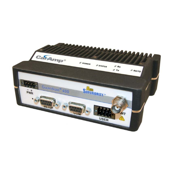
PHYSICAL DESCRIPTION Guardian consists of two PCBs, one that includes the modem circuitry and the other the radio module. Both are installed in a cast aluminum case. The unit is not hermetically sealed and should be mounted in a suitable enclosure when dust, moisture, and/or a corrosive atmosphere are anticipated. -
Page 10: User Interface Port
Amber (Solid or Blinking) Guardian is Programming Guardian hardware fault Status Green Guardian no faults, normal operations Guardian has a fault condition, check unit status Amber (Solid or Blinking) Guardian detects high background noise Green Receiving data Transmitting data Blinking Amber The unit wants to transmit, but is inhibited. -
Page 11: Setup And Com Ports
In general, equipment connected to the Guardian’s SETUP / COM serial port is Data Terminal Equipment (DTE) and a straight-through cable is recommended. Note: If a DCE device is connected to the Guardian SETUP / COM port, a null modem cable/adapter is required. -
Page 12: Antenna Connector
Enable NOTE: The White Enable line must be tied to the red positive lead of the connector for the Guardian to power up. Bringing the Enable line low is a request for the unit to power down. If the unit is writing to any non-volatile memory, it will complete the operation before powering down. -
Page 13: Chassis Dimensions
1.4.7 CHASSIS DIMENSIONS Figure 1-2 – Dimensions of the Guardian Chassis and Mounting Plate PART NUMBERS AND AVAILABILITY 1.5.1 GUARDIAN RADIO provides a breakdown of the Guardian part number 140-50X6-Y0Z. Table 1-5 Table 1-5 – Part Number Breakdown Model Number... -
Page 14: Accessories And Options
TNC-Male to N-Male 72” 250-0697-105 TNC-Male to N-Female 18” 250-0697-106 * The Guardian Demo Kit includes two of each of the following: Guardian, rubber duck antennas, adapters, attenuators, power cables, and power supplies. Table 1-7 – Antenna Kits ITEM PART NUMBER Antenna Kit*: 138-143 MHz 6.5 dBd... -
Page 15: Product Warranty
250-0200-100 PRODUCT WARRANTY It is our guarantee that every Guardian Radio modem will be free from physical defects in material and workmanship for TWO YEARS from the date of purchase when used within the limits set forth in Appendix A: Specifications. -
Page 16: Rma Request
1.10 DOCUMENTATION AND DOWNLOADS CalAmp reserves the right to update its products, software, or documentation without obligation to notify any individual or entity. Product updates may result in differences between the information provided in this manual and the product shipped. -
Page 17: System Architecture And Network Planning
Industry sectors with SCADA systems include energy utilities, water and wastewater utilities, and environmental groups. The Guardian is intended for use in the Industrial Monitoring and SCADA market. The range of the Guardian is dependent on terrain, RF (radio frequency) path obstacles, and antenna system design. This section provides tips for selecting an appropriate site, choosing an antenna system, and reducing the chance of harmful interference. -
Page 18: Point-To-Multipoint
The device is typically an RTU or PLC used by the message service to store the received message then it transmits the message to the intended recipient. Guardian Manual 001-5006-000 Rev 0 18 |... -
Page 19: Network Using A Guardian For Online Diagnostics
Online Diagnostics are accumulated in the monitoring Guardian for the last 15 stations heard. This information may be viewed using the Online Diagnostics utility. For larger networks, the Guardian can output raw diagnostic data through the Setup port which may be interpreted for network management by the Field Programming Software Online Diagnostics utility or by a user-supplied software program. -
Page 20: Site Survey
SELECTING ANTENNA AND FEEDLINE The Guardian can be used with a variety of antenna types. The exact style used depends on the physical size and layout of a system. The Guardian device has been tested and approved with antennas having a maximum gain of 10 dBi. -
Page 21: Yagi Antenna
A 3 dB loss in signal strength due to cable loss and/or bad connections represents a 50% reduction in signal strength. Guardian Manual 001-5006-000 Rev 0 21 |... -
Page 22: Rf Exposure Compliance Requirements
2.4.6 RF EXPOSURE COMPLIANCE REQUIREMENTS The Guardian radio is intended for use in the Industrial Monitoring and Control and SCADA markets. The Guardian unit must be professionally installed and must ensure a minimum separation distance listed in the table below between the radiating structure and any person. -
Page 23: Radio Interference
Approximately 99.9% reliability with high tolerance to fading. RADIO INTERFERENCE Interference is possible in any radio system. However, since the Guardian is designed for use in a licensed system, interference is less likely because geographic location and existing operating frequencies are normally taken into account when allocating frequencies. -
Page 24: Setup And Configuration
Primary power for the Guardian must be within 10-30 VDC and be capable of providing a minimum of 10 watt supply for Tx @ 1W, 40 watt supply for Tx @ 5W, or 60 watt supply for Tx @ 10 W. (In Guardian Demo Kits, a power connector with spring terminals is provided with each unit.) Observe proper polarity when connecting the... -
Page 25: Connect Guardian To Programming Pc
3. Remove Insertion Tool. Check wire connection. CONNECT GUARDIAN TO PROGRAMMING PC Connection to a Guardian is established through an RS-232 (straight through) or (non-null) cable connected to the setup port of the Guardian and the COM port of the PC. -
Page 26: Unit Status
Short ID numbers to avoid ambiguity in Online Diagnostics reports. The Guardian Field Programming Software may be used to check the value of the Short ID. When setting up a network, we recommend checking each unit to make sure there is no duplication of Short ID numbers. -
Page 27: Offline Diagnostics
See section 5.1.10 for more on Offline Diagnostics in the Field Programming Software. 4.2.3 REMOTE COMMANDS Remote commands that may be sent using the Offline Diagnostics utility include: Sample network statistics (monitoring online diagnostics) Get statistics (diagnostics) Guardian Manual 001-5006-000 Rev 0 27 | P a g e... -
Page 28: Guardian Field Programming Software
The Guardian Field Programming Software provides programming and diagnostics for the Guardian wireless modem. The Field Programming Software allows the user to edit and program user programmable settings, interactively tune modem and RF parameters, and monitor diagnostic data from the Guardian. See Figure 5-1 the Guardian Field Programming Software startup screen. -
Page 29: Com Port Settings
Guardian programming is done through the PC’s Primary COM Port. Primary and secondary COM ports are configured with the Field Programming Software. The programming cable (included in the Demo Kit) is connected from the Setup Port on the Guardian to the PC’s COM port configured as the Primary Port. 5.1.2 PORT SETTINGS... - Page 30 Selecting the Swap Com Ports button moves the Secondary COM Port settings to the Primary COM Port (and moves the Primary COM Port to the Secondary settings). Since Guardian programming is done through the Primary COM Port, this is useful when two units are connected to the Primary and Secondary COM Ports. A Swap COM Ports allows the second unit to be programmed without switching programming cables.
-
Page 31: Port Statistics
RTS shows the current state of the RTS (request to send) line. RTS is an output from the PC. DTR shows the current state of the DTR (data terminal ready) line. DTR is an output from the PC. Guardian Manual 001-5006-000 Rev 0 31 |... -
Page 32: User Configuration
5.1.4 USER CONFIGURATION The User Configuration screen is accessed from the Utilities drop down menu or the Config icon on the tool bar. Figure 5-5 – User Configuration Screen Guardian Manual 001-5006-000 Rev 0 32 | P a g e... - Page 33 This field is used to set the Station ID (CWID) or FCC Call Sign for the Guardian Modem. If enabled, the Guardian will transmit the CWID string as Morse Code at the time interval chosen on the slider.
-
Page 34: Link Configuration
Guardian will wait until the channel is clear before sending the data. No Tx on RX Carrier: Enables CSMA. Guardian will check the RF channel for an RF carrier. If carrier is found, the Guardian will wait until the channel is clear before sending the data. -
Page 35: Modem Settings
Figure 5-7 – Link Configuration Screen Default Tab This tab is used to set all of the Guardian Modem's default settings. The default settings will be used in any of the 8 links where the Default checkboxes are checked. 5.1.5.1 MODEM SETTINGS Figure 5-8 –... - Page 36 • Received Signal Strength (in dBm) Output Online Diagnostic Data to Setup Port Allows the user to configure the Guardian Modem to output online diagnostics through the Setup Port. The default value is “Disabled” (unchecked). Repeater Mode (Extended T1 RTS-CTS) The Repeater Mode option extends transmitter turn-on time to allow use in a repeater network.
- Page 37 (i.e., fading in a moving vehicle) causes problems. Carrier Detect On Threshold The slider allows the user to set the minimum RSSI level that the Guardian Modem will recognize as a valid carrier and begin decoding data. 5.1.5.2 RF LINK The RF Link section provides the interface for programming various radio operating parameters.
-
Page 38: Com Port
Select RS-485 to use the RS-485 compatible interface in the User Connector for incoming and outgoing data. The RS-422 and RS-485 interface in the Guardian is a 4-wire (2 transmit and 2 receive) interface. If your interface is also 4 wire, you may select Full Duplex (4-wire) to allows simultaneous transmission and reception of data. If you require a two wire interface, deselect the Full Duplex (4-wire) box. -
Page 39: Version Request
― DOX mode. Data is sent whenever it is present at the port. Flow control is not required. All RS-422 and RS- 485 connections are run through DOX mode. ― RTS/CTS mode. Data is sent after the device raises the RTS and the Guardian returns a CTS signal to the device. This setting is unique to the COM Port and RS-232. -
Page 40: Diagnostic Ids, Alarms And Filters
Guardian configurations so they can be easily written into multiple Guardian Modems. Note: CalAmp recommends a Read be done anytime an initial connection is made to the Guardian Setup Port before accessing the Link Configuration screen. This will help avoid writing erroneous parameters to the connected unit. -
Page 41: Offline Link Test
NOTE: An Offline Link Test requires suspension of user network operation. Remote Select Local ID The Long ID of the unit connected to the computer. The Short ID is displayed. Guardian Manual 001-5006-000 Rev 0 41 | P a g e... - Page 42 Allows the user to determine the delay between the transmission of data blocks in 0.05 second intervals (0.00 to 120.00 seconds). Clear Allows the user to clear the display (blocks transmitted, blocks received and link quality). Guardian Manual 001-5006-000 Rev 0 42 | P a g e...
-
Page 43: Offline Diagnostics
Allows the user to choose Current, Low or High Diagnostics. Current shows the value of the last requested parameters. Low or High displays the lowest or highest value of the parameters since the last Clear was performed or the last time power was removed. Guardian Manual 001-5006-000 Rev 0 43 | P a g e... - Page 44 Shows the user the Long and Short ID are not the same. RSSI Level Shows the current RSSI level (in dBm) while the Local unit is receiving. Temperature Shows the internal case temperature (in Celsius). Guardian Manual 001-5006-000 Rev 0 44 | P a g e...
- Page 45 Displays the progress of obtaining Remote Diagnostics. Tx Tone The Tx Tone button will send a remote or local command to cause the Guardian to transmit a tone. This can be used to create network traffic so that offline diagnostics of remotes can be monitored.
-
Page 46: Online Diagnostics
“>” character will designate a value greater than the high alarm. If Online Diagnostics are received and a diagnostic field falls outside the filter limits, the diagnostic information will be considered invalid and will not be displayed. Guardian Manual 001-5006-000 Rev 0 46 | P a g e... - Page 47 Displays the supply voltage (in volts) of the unit transmitting the diagnostics. FwdP Displays the forward power (in watts) of the unit transmitting the diagnostics. RevP Displays the reverse (reflected) power (in watts) of the unit transmitting the diagnostics. Guardian Manual 001-5006-000 Rev 0 47 | P a g e...
- Page 48 The Clear button allows the user to clear the display and current Online Diagnostics. Save The Save button allows the user to save the current Online Diagnostics to a file. A maximum of 4096 lines of data can be saved. Guardian Manual 001-5006-000 Rev 0 48 | P a g e...
-
Page 49: Packet Test
Shows the number of data packets that the Remote device has returned to the Host. Host Packets Rx’ed Shows the number of data packets the Host device has received from the Remote. Guardian Manual 001-5006-000 Rev 0 49 | P a g e... - Page 50 A Y-cable is required for this option (with transmit connections split to the transmitting device and receive connections split to the receiving device). A computer with 1 COM port is utilized for this option. Guardian Manual 001-5006-000 Rev 0 50 |...
-
Page 51: Array Test
Type of Data allows the user to select the data pattern for each packet. The size for each data pattern is listed in the pattern format explanations (packets are built using one of four possible patterns). Guardian Manual 001-5006-000 Rev 0 51 |... - Page 52 FE 11 22 33 44 55 66 77 88 99 AA BB CC DD EE FF FF 11 22 33 44 55 66 77 88 99 AA BB CC DD EE FF Guardian Manual 001-5006-000 Rev 0 52 | P a g e...
-
Page 53: Ascii / Hex Terminal
Primary and Secondary COM Ports (configured in the Port Settings screen - see Section 5.1.2) Data is sent according to the port configuration set up in the Port Settings screen. Figure 5-19 – ASCII Terminal Screen Guardian Manual 001-5006-000 Rev 0 53 | P a g e... -
Page 54: Program Firmware
Secondary COM Port (set up in the Port Settings screen). 5.1.15 PROGRAM FIRMWARE The Program Firmware screen is accessed from the Utilities drop down menu. Figure 5-20 – Program Firmware Screen Guardian Manual 001-5006-000 Rev 0 54 | P a g e... -
Page 55: End To End Test
The testing setup requires a computer running the Field Programming Software attached to each user COM port on the Guardian wireless modems. The Utilities will allow the user to send ASCII text or Hex characters through the Guardians being tested. - Page 56 Figure 5-21 area. The ASCII text message is then sent out the first Guardian through the computer’s primary port once the “Send “button is clicked. The sent ASCII message is then displayed in the Tx Data area of the ASCII Terminal...
- Page 57 If the message was not displayed as typed, then a problem may exist in the system. Check all parameters and connections in the system. The signal level should also be checked again. The Guardian’s Link Test utility can be used to verify a communication path.
-
Page 58: Guardian Specifications
5.50" W x 2.125” H x 4.25" D (13.97 x 5.40 x 10.8 cm) Shipping Weight 2.4 lbs. (1.1 Kg) Mounting Options Mounting plate/pattern & DIN Rail Fan Output 5VDC, 400mA max. Guardian Manual 001-5006-000 Rev 0 58 | P a g e... - Page 59 > 75 dB Rejection < 1 ms (Standard) TX to RX Time 5 ms (ETSI Versions) Channel < 15ms (Band-End to Band-End) Switching Time Receive Input 17 dBm (50mW) max. Power Guardian Manual 001-5006-000 Rev 0 59 | P a g e...
- Page 60 TNC female (Tx/Rx), SMA female (Rx) – Dual-Port and Full-Duplex models only Serial Setup Port DE-9F Serial Terminal Server DE-9F User Interface I/O Right angle, 8 contacts (male) Power - I/O I/O Right angle, 4 contacts (male)Power Plug Guardian Manual 001-5006-000 Rev 0 60 | P a g e...
- Page 61 140-5046-301 140-5046-500 450 - 512 MHz NP4-5046-300 773B-5046300 140-5046-501 450 - 512 MHz NP4-5046-300 773B-5046300 140-5096-500 928 - 960 MHz NP4-5096-500 773B-5096500 140-5096-501 928 - 960 MHz NP4-5096-500 773B-5096500 Guardian Manual 001-5006-000 Rev 0 61 | P a g e...
-
Page 62: Product Warranty
PRODUCT WARRANTY PRODUCT WARRANTY CalAmp warrants to the original purchaser for use ("Buyer") that data telemetry products manufactured by DRL ("Products") are free from defects in material and workmanship and will conform to DRL's published technical specifications for a period of, except as noted below, one (1) year from the date of shipment to Buyer. DRL makes no warranty with respect to any equipment not manufactured by DRL, and any such equipment shall carry the original equipment manufacturer's warranty only. - Page 63 CalAmp delivers cost-effective high quality solutions to a broad array of customers and end markets. CalAmp is the leading supplier of Direct Broadcast Satellite (DBS) outdoor customer premise equipment to the U.S. satellite television market. The Company also provides wireless data communication solutions for the telemetry and asset tracking markets, private wireless networks, public safety communications and critical infrastructure and process control applications.
Need help?
Do you have a question about the GUARDIAN and is the answer not in the manual?
Questions and answers