
Related Manuals for CalAmp 882?EVDO?XXX


Summary of Contents for CalAmp 882?EVDO?XXX
- Page 1 882‐EVDO‐XXX CDMA Cellular Data Modem & IP Router User Manual 001‐0003‐822 Revision 4; September 2011 ...
- Page 2 Copyright Notice ©2010 CalAmp. All Rights Reserved. CalAmp reserves the right to modify the equipment, its specification or this manual without prior notice, in the interest of improving performance, reliability, or servicing. At the time of publication all data is correct for the operation of the equipment at the voltage and/or temperature referred to. Performance data indicates typical values related to the particular product. No part of this documentation or information supplied may be divulged to any third party without the express written consent of CalAmp. Products offered may contain software which is proprietary to CalAmp. The offer or supply of these products and services does not include or infer any transfer of ownership. Modem Use The 882 CDMA Series modems are designed and intended for use in fixed and mobile applications. “Fixed” assumes the device is physically secured at one location and not easily moved to another location. Please keep the cellular antenna of the 882 CDMA Series modem at a safe distance from your head and body while the modem is in use (see below). Important Maintain a distance of at least 20 cm (8 inches) between the transmitter’s antenna and any person while in use. This modem is designed for use in applications that observe the 20 cm separation distance. Interference Issues Avoid possible radio frequency (RF) interference by following these guidelines: The use of cellular telephones or devices in aircraft is illegal. Use in aircraft may endanger operation and disrupt the cellular network. Failure to observe this restriction may result in suspension or denial of cellular services to the offender, legal action or both. Do not operate in the vicinity of gasoline or diesel‐fuel pumps unless use has been approved and authorized. Do not operate in locations where medical equipment that the device could interfere with may be in use. Do not operate in fuel depots, chemical plants, or blasting areas unless use has been approved and authorized. Use care if operating in the vicinity of protected personal medical devices, i.e., hearing aids and pacemakers. Operation in the presence of other electronic equipment may cause interference if equipment is incorrectly protected. Follow recommendations for installation from equipment manufacturers. UL Installation Instructions ...
- Page 3 REVISION HISTORY February 2008 Released June 2008 Rev 2 - updates include Firewall functionality, new screen formats. September 2009 Rev 3 - updates include Black case with new power supply connector, Internal/External Serial ports, new screen format configuration file save & upload, and other functionality revisions. September 2011 Rev 4 - Updated to include UL Certification, Instructions and Ratings.
-
Page 4: Table Of Contents
TABLE OF CONTENTS – E ........................9 – Copyright Notice ............................. 9 Modem Use ............................. 9 Interference Issues ..........................9 Mobile Application Safety ........................10 – W .................... 11 – Module Identification..........................11 General Description .......................... - Page 5 TABLE OF CONTENTS Comment ............................28 – N ................... 29 – LAN Configuration ..........................29 Ethernet IP Address .......................... 30 Ethernet Subnet Mask ........................30 LAN Masquerade ..........................30 DNS Resolving ............................. 30 DNS Auto............................
- Page 6 TABLE OF CONTENTS – – ) ............................... 39 SNMP Configuration ..........................39 SNMP ..............................39 Read-only Community Name ......................39 Read-write Community Name ......................39 – S ......40 – PPTP Client Configuration ........................40 ...
- Page 7 TABLE OF CONTENTS Remote Port ............................48 Local Port ............................48 PAD Mode ............................48 Pad Protocol ............................48 PAD Log ............................48 – – R ....................49 Periodic Reset Timer ..........................50 Periodic Reset Timeout ........................
- Page 8 TABLE OF CONTENTS Log File Actions ........................... 57 Store in Modem..........................57 Display .............................. 57 TFTP to Server ..........................57 TFTP Server IP ..........................57 – – S ....................58 General Specifications .......................... 58 ...
-
Page 9: S E C T I O N 1 - P R E F A Ce
– Copyright Notice ©2009 CalAmp. All Rights Reserved. This manual covers the operation of the CalAmp 882-EVDO Cellular Data Modem IP Routers. Specifications described are typical only and are subject to normal manufacturing and service tolerances. CalAmp reserves the right to modify the equipment, its specification or this manual without prior notice, in the interest of improving performance, reliability, or servicing. -
Page 10: Mobile Application Safety
Road safety is crucial. Observe National Regulations for cellular telephones and devices in vehicles. Avoid potential interference with vehicle electronics by correctly installing the 882-EVDO modem. CalAmp recommends installation by a professional. Page 10 of 62... -
Page 11: S E C T I O N 2 - P R O D U C T O V E R V I Ew
ESN Hex: Same number as above but in a special HEX format. General Description The 882-EVDO Cellular Data Modem & IP Router from CalAmp is the ideal solution for a wide range of cellular data network serial and Ethernet connectivity requirements. -
Page 12: External Connections
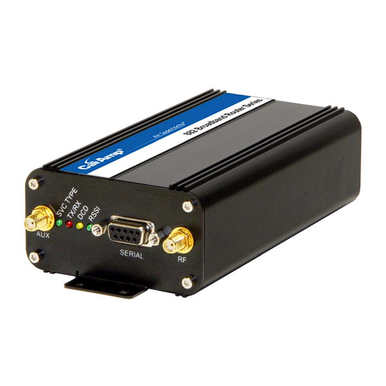
External Connections Front panel connections Fig. 2.1 882-EVDO Front Panel Panel Connection Description Indicator Solid = Higher speed service SVC TYPE Service Type Blinking = Lower speed service Off = No service Indication of data transmission or reception TX/RX Transmit/Receive activity Indicates modem’s connection on the cellular Data Carrier Detect... -
Page 13: Back Panel Connections
Back panel connections Fig. 2.2 882-EVDO Back Panel Panel Connection Description Indicator ETHERNET RJ-45 Ethernet Interface for Ethernet connection to devices Interface for external devices (i.e., memory USB HOST drives or GPS devices). ODP use only. One second hold for unit reset. If held for RESET at least 4 sec, will reconfigure unit to factory default settings. -
Page 14: Primary Antenna
Accessory/Option Order Number Description 401-7500-001 4” Rubber Duck Antenna L2-ANT0003 3” Mag Mount Antenna 150-7001-001 110 VAC Input Power 150-7500-002 DC Power Cable L2-CAB0002 DB-9 Serial Cable L2-CAB0006 Ethernet cable Primary Antenna The primary antenna connection on the 882-EVDO modem is a female connector, therefore you must purchase an antenna with a SMA male connector. -
Page 15: Package Contents
The 882-EVDO modem can be configured via HTML web pages. You will need a CDMA Cellular account. For TCP/IP please request a packet data account with Mobile IP and optionally Static IP or Simple IP (SIP). This is carrier dependent. The modem is configured with default settings and is ready to be configured via HTML. -
Page 16: Accessing The Modem's Homepage
Find and select “Internet Protocol (TCP/IP)” from the list box and then click the “Properties” button (Figure 3.1). The TCP/IP configuration window will pop up, refer to Figure 3.2. Under the General tab, select radio button “Obtain an IP address automatically” and “Obtain DNS server address automatically”... - Page 17 Figure 3.4: 882-EVDO Home Page The PPP status on the Home page will show DOWN because the new device is not provisioned. Also, the MDN/MTN or MSID/IMSI (MIN) lines may show an invalid phone number indicating the unit has not been provisioned. The modem must first be provisioned with the specific carrier before connecting with the cellular network.
-
Page 18: S E C T I O N V E R I Z O N W I R E L E S S P R O V I S I O N I N G I N F O R M A T I O N O T A Sp
– – When a new modem is powered up for the first time, most of the MDN/MTN and MSID/IMSI (MIN) information is blank or has outdated PRL for that geographical area that should be updated. In order to use the modem, it must be activated by the specific carrier once the MDN/MTN and MSID/IMSI (MIN) have been provided from the carrier for the ESN of the unit needing activation. -
Page 19: Manual-Entry Activation
Manual-Entry Activation If provisioning must occur in a roaming area, make sure to have a medium to strong signal strength because manual-entry activation will be required. Select Provisioning from the side menu bar. Input the MDN/MTN and MSID/IMSI (MIN) given by your provider ... -
Page 20: S E C T I O N S P R I N T P R O V I S I O N I N G I N F O R M A T I O N O M A Dm
– – When a new modem is powered up for the first time, most of the MDN/MTN and MSID/IMSI (MIN) information is blank or has outdated PRL for that geographical area that should be updated. In order to use the modem, it must be activated by the specific carrier once the MDN/MTN and MSID/IMSI (MIN) have been provided from the carrier for the ESN of the unit needing activation. - Page 21 Figure 5.1: Sprint Provisioning Page Page 21 of 62...
-
Page 22: Manual-Entry Activation
Manual-Entry Activation If provisioning must occur in a roaming area, make sure to have a medium to strong signal strength because manual-entry activation will be required. Select Provisioning from the side menu bar. Input the MDN/MTN and MSID/IMSI (MIN) given by your provider. ... -
Page 23: Advanced Settings
Advanced Settings The Advanced Settings page supports the programming of 2 profiles that may be used to login to the cellular provider's network. It also allows the user to choose which profile is active. A provider may support alternate networks whose use is limited to specific customers. Login information must be gathered from the provider. -
Page 24: Provisioning Screen Definitions
Profile Enable: On/OFF This field indicates if the profile is enabled. It is possible to enable both profiles. Whether to enable 1 or both profiles should be based on information from the provider. NAI: This field should be set the Network Access ID supplied by the provider. Home IP Address: This parameter should be set to the Home IP Address supplied by the provider. -
Page 25: Msid/Min/Imsi
The actual phone number of the device as supplied by the carrier. When the unit is successfully provisioned, the phone number for the user account will be displayed. MSID/MIN/IMSI: This number is used by the Mobile Telephone Network and will be different if ported from another carrier (not used by end user of device). - Page 26 After the modem has been successfully provisioned, the cellular data connection can be enabled. At the Home page select Cell Connection from the side menu bar, then the Dial Settings tab. Fill out the Dial Number, User, and Password fields required for the specific carrier account. The default dial number of atd#777 is shown in Figure 6.1 below.
- Page 27 as other PPP parameters. The MDN/MTN number should match the phone number provided on the account. Figure 6.2: 882-EVDO Successful Connection Parameters The 882-EVDO modem is ready to browse the web. More detailed configuration information and activation of other features of the 882-EVDO modem are given in the following sections. Page 27 of 62...
-
Page 28: S E C T I O N 7 - M A C F I L T E R I N G S E T T I N Gs
– – Selecting LAN Settings from the left menu bar, then the MAC Filtering tab, brings up the MAC Filtering configuration page. MAC filtering allows up to five unique device MAC addresses access to the network. Figure 7.1: MAC Filtering Page MAC Filtering Support MAC Filtering: Select Enable to allow MAC filtering. -
Page 29: S E C T I O N 8 - L A N C O N F I G U R A T I On
– – Selecting LAN Settings from the left menu bar brings up the LAN Settings configuration page. From this page the modem’s IP address, DNS settings, DHCP settings, and Remote Administration parameters are configured. Refer to Figure 8.1 below. Figure 8.1: LAN Settings Page LAN Configuration Page 29 of 62... -
Page 30: Ethernet Ip Address
Ethernet IP Address: This sets the IP address of this device and is the address used to access the configuration pages. If the IP address changes you will have to re-enter the new IP address in your browser to access the configuration pages. -
Page 31: Remote Configure
Enter the port number to be used by the LandCell local web server. This can be changed if there is a port conflict with an external device. As an example, when the remote Ethernet device is restricted to port 80 only, the local port can now be changed to another unreserved port. Remote Configure: Selecting Enable will allow remote access to the modem’s configuration screens through the cellular network connection. -
Page 32: S E C T I O N 9 - D M Z / P O R T F O R W A R D I N G S E T T I N Gs
– – Selecting Router from the left menu bar, then the Port Forwarding tab, brings up the port forwarding configuration page. Port Forwarding is a technique for transmitting and receiving network traffic through a router that involves re-writing the source and/or destination IP addresses and usually the TCP/UDP port numbers of IP packets as they pass through. -
Page 33: Dmz Support
DMZ Support DMZ: When set to Enable, will allow the modem to use DMZ routes using the address set in the Destination IP Address. When set to Disable, will shut down the DMZ functionality. This can be used when one Ethernet device per modem is used. DMZ will forward all ports to the device except for the ports already specified, see below: Web server port, remote administration incoming port, SSH port, Telnet port, SNMP port and incoming serial PAD ports, and any ports listed in the IP mapping table. -
Page 34: Inbound Port
Inbound Port: This sets the external port number for incoming requests. To avoid conflict, never reuse any of the same ports as described in the DMZ section above. Destination IP Address: The IP address of the tethered device for which the port specified in the inbound port field will be forwarded to. -
Page 35: S E C T I O N 1 - D Y N A M I C D Ns
– – Selecting Router from the left menu bar, then the Dynamic DNS tab, brings up the dynamic DNS configuration page. Dynamic DNS is a system which allows the domain name data of a computer with a varying (dynamic) IP addresses held in a name server to be updated in real time in order to make it possible to establish connections to that machine without the need to track the actual IP address themselves at all times. -
Page 36: Port Number
Port Number: The port number for the internet address given above. Default is 8245. User Account: The username used when setting up the account. Used to login to the Dynamic DNS service. User Password: The password associated with the username account. Hostname: The hostname identified to the Dynamic DNS service. -
Page 37: S E C T I O N R O U T E R S E T T I N Gs
– – Selecting Router from the left menu bar, then the Static Routes tab, brings up the static routing configuration page. Static route tables are created from the Routing screen and appear at the bottom. Static Routing refers to a manual method used to set up routing between networks. Figure 11.1: Router Settings page Static Routes Route Name:... -
Page 38: Gateway Ip Address
Gateway IP Address: Selects ppp (this modem's wireless internet connection), pptp (VPN Client), or the local network IP address for the gateway to the destination address. As an example, data by default will go through ppp. But if pptp (VPN Client) is on, routing can go around the VPN by selecting ppp. Local IP Address: This is only used if local IP Addr was selected for gateway. -
Page 39: Snmp Configuration
– – Selecting Diagnostics from the left menu bar, then the SNMP tab, brings up the Simple Network Management Protocol configuration page. SNMP is used in network management systems to monitor network-attached devices for conditions that warrant administrative attention. SNMP version v1 is supported. -
Page 40: S E C T I O N P O I N T T O P O I N T T U N N E L I N G P R O T O C O L S E T T I N Gs
– – Selecting VPN from the left menu bar will display the Point-to-Point Tunneling Protocol (PPTP) configuration page. PPTP is a method to implement a virtual private network (VPN). Figure 13.1: PPTP Settings page Page 40 of 62... -
Page 41: Pptp Client Configuration
PPTP Client Configuration PPTP Client: Selecting Enable will allow the PPTP functionality. Selecting Disable will shut off PPTP functionality. Set Default Route to PPTP: Selecting Enable will route all IP traffic through the PPTP connection. Selecting Disable will not route IP traffic through the PPTP connection. -
Page 42: S E C T I O N E X T E R N A L S E R I A L P O Rt
– – Selecting Serial from the left menu bar, then the External Serial tab, brings up the serial port and PAD settings page. The External Serial screen is used to configure the RS-232 Serial Port parameters and Packet Assembler and Dis-assembler (PAD) functionality. This acts as a serial to IP (and IP to serial) converter without the need to purchase a separate serial to IP converter. -
Page 43: Baud Rate
Baud Rate: Sets the baud rate of the serial port. Settings may range from 300 to 115,200 bits per second. The default baud rate is 115,200 bps. Inter Character Timeout: Sets the interval between packets being sent, no matter the size, from 1 to 65,535 ms. DTR: Defines the Data Terminal Ready behavior. -
Page 44: Dsr
DSR: Sets the Data Set Ready to Always On, On When Available, On When Connected or Always Off. The DSR parameter determines how the modem controls the state of the Data Set Ready circuit. Always On: DSR is always on. On When Available: DSR is on when the RF signal present and phone registered on network. -
Page 45: Incoming Friendly Ip Address
Incoming Friendly IP Address: This specifies a remote IP address that is allowed to access the modem. A wildcard IP address of 0.0.0.0 allows all remote IP address to access the modem. Incoming Port: Sets the port number used to forward incoming traffic to the serial port. Inbound traffic with this port will be forwarded to the serial port in client mode. -
Page 46: Server Inactivity Timeout
Timeout: A new client will be accepted only after a specified timeout. The duration of the timeout is specified by the Inactivity timeout, or the Hard timeout, or a combination of both. The default value is New Client. Server Inactivity Timeout: Time after which the current connection with Client will be terminated without warning. -
Page 47: S E C T I O N I N T E R N A L S E R I A L P O Rt
– – Selecting Serial from the left menu bar, then the Internal Serial tab, brings up the serial port and PAD settings page. The Internal Serial screen is used to configure the internal RS232 Serial Port parameters and Packet Assembler and Dis-assembler (PAD) functionality. The PAD feature forwards requests that come in on a specific port to the internal serial port. -
Page 48: Pad Settings
PAD Settings Remote IP Address: Sets the IP address of the device using the PAD functionality. Remote Port: Sets the port number used by the remote device to accept requests from the LandCell. Local Port Sets the port number used by the LandCell to accept requests from the remote device. PAD Mode: Select buttons to set the PAD mode of the LandCell as a Server or Client. -
Page 49: S E C T I O N S Y S T E M M O N I T Or
– – Selecting Cell Connection from the left menu bar, then the System Monitor tab, brings up the system monitor page. The System Monitor page allows the user to set up additional self-monitoring for the modem to determine when service provider connections may have been terminated. Refer to Figure 16.1 below. -
Page 50: Periodic Reset Timer
Periodic Reset Timer Periodic Reset Timeout: Sets the Periodic Modem Reset timer to an Interval time, a Scheduled day, or disables it. Interval Length: Sets the Periodic Modem Reset time from 15 to 65,535 minutes. The Periodic Reset is disabled when set to 0. -
Page 51: Tx Bytes
Tx Bytes: The total number of bytes transmitted by the modem to the cell network. All statistics will be cleared automatically if this count exceeds 1 billion (1,000,000,000). Tx Packets: The total number of TCP and UDP packets transmitted by the modem to the cell network. Tx Errors: The number of corrupted TCP and UDP packets received by the modem that were meant to be transmitted on the cell network. -
Page 52: S E C T I O N L O C A T I On
– – The Location page displays the ESN, latitude, and longitude associated with the LandCell. It also allows for configuration of the GPS fix type, a remote destination to send data, and an interval defining how often to send that data. Figure 17.1: GPS Location page Location Data ESN:... -
Page 53: Gps Reporting Settings
GPS Reporting Settings GPS Type: Sets the GPS fix type. If True GPS is used, the cell module determines the GPS coordinates by itself. If Assisted GPS is used, the cell module uses a Position Determination Entity located at the GPS IP Address and Port to determine its location. -
Page 54: S E C T I O N F I R M W A R E U P D A Te
CalAmp web site and manually update the unit by uploading the new firmware. Refer 18.1 below. Please check for the latest versions and release notes on www.calamp.com. -
Page 55: Upload New Firmware
Upload New Firmware File: Field to input the downloaded update file to the modem. The Browse button can be used to locate the file in a specific folder. The update can be done remotely if Remote Administration is enabled. Progress: Displays the update progress after the Save button has been pressed Configuration File File:... -
Page 56: S E C T I O N L O G G I Ng
Selecting Diagnostics from the left menu bar, then the Logging tab, brings up the logging page. The Logging page provides a way to capture the current status log of the modem. Such a log may be useful to CalAmp Technical Services personnel to help resolve operational problems. Refer to Figure 19.1 below. -
Page 57: Log File Actions
Log File Actions Store in Modem: Selecting Store in Modem and pressing Go creates a current status log. Completing a Store in Modem will overwrite existing status logs. Display: Selecting Display and pressing Go will display a previously stored log directly to the web browser. You can use your mouse to select the text, copy it, and paste it into a text editor to save the log on your computer. -
Page 58: General Specifications
– – Product specifications are subject to change without notice. General Specifications Interface Connectors: RS-232 DE-9S Connector (DCE) 10/100 Base-T Full Duplex USB Host Controller Power Connector I/O Power Connector: Molex Micro-Fit, 4 pin, PN: 43045-400 LED Indicators: SVC-TYPE, TX/RX, DCD, RSSI Antenna Interface: SMA female Size:... -
Page 59: Mechanical Specifications
UL Ratings USL, CNL – Information Technology Equipment for use in Hazardous Locations, Class I, Div 2, Groups A, B, C, D, using Class 2 Power Supply. See below for UL Ratings. Maximum Rated Operating Model Description Ratings Ambient Temperature Temperature Code CDMA Data 9‐28 VDC ... -
Page 60: S E C T I O N A B B R E V I A T I O Ns
– – Abbreviation Description CDMA Code Division Multiple Access Clear to Send Data Carrier Detect Electronic Serial Number EVDO Evolution Data Optimized GPRS General Packet Radio Service Global Positioning System IOTA Internet Over the Air Light Emitting Diode OMA-DM Open Mobile Alliance Device Management Over the Air OTASP Over the Air Service Provisioning... -
Page 61: S E R V I C E A N D S U P P O Rt
– Product Warranty, RMA and Contact Information CalAmp guarantees that every 882-EVDO Cellular Modem will be free from physical defects in material and workmanship for one (1) year from the date of purchase when used within the limits set forth in the Specifications section of this manual. -
Page 62: A P P E N D I X 1 - W A R R A N T Y S T A T E M E N T
– – CalAmp warrants to the original purchaser for use ("Buyer") that data telemetry products manufactured by DRL ("Products") are free from defects in material and workmanship and will conform to DRL's published technical specifications for a period of, except as noted below, one (1) year from the date of shipment to Buyer.
Need help?
Do you have a question about the 882?EVDO?XXX and is the answer not in the manual?
Questions and answers