
Related Manuals for CalAmp Integra-Tr


Summary of Contents for CalAmp Integra-Tr
- Page 1 USAT Contact USATCORP.COM for more information or quantity pricing USATCORP.COM 1-888-550-8728 INTEGRA-TR™ WIRELESS MODEM FOR LICENSED SPECTRUM USER MANUAL PN 001-4008-100 REV 6 FEBRUARY 2013...
- Page 2 INTEGRA-TR™ WIRELESS MODEM FOR LICENSED SPECTRUM USER MANUAL PN 001-4008-100 REV 6 FEBRUARY 2013...
-
Page 3: Revision History
REVISION HISTORY Rev 0 June 2011 Initial Release. Rev 1 August 2011 Changed Dual Band references to Dual IF, sections 1.6 and 1.8. Deleted Synthesizer reference, section 4.3.1.3. Rev 2 January 2012 Added VHF Dual Band specifications and part numbers, splinter channel frequencies and FCC/IC indicators. Rev 3 April 2012 Corrected part numbers in section 1.6. -
Page 4: Important Notices
(i.e., have errors), or be totally lost. Significant delays or losses of data are rare when wireless devices such as the Integra-TR are used in a normal manner with a well-constructed network. Integra-TR should not be used in situations where failure to transmit or receive data could result in damage of any kind to the user or any other party, including but not limited to personal injury, death, or loss of property. -
Page 5: Table Of Contents
Point-to-Point System ............................17 3.2.2 Point-to-Multipoint System ..........................18 3.2.3 Extending a Landline (Tail Circuit) ........................20 Integra-TR Field Programming Software ........................... 21 Integra-TR Programmer Window ..........................21 File Menu ................................... 21 Edit Menu................................... 22 4.3.1 Setup Modem/Radio Parameters ........................23 4.3.2... - Page 6 4.4.11 Ping Test ................................55 4.4.12 ASCII/Hex Terminal ............................57 Program Code Menu ..............................59 Network Optimization ............................... 60 Choose the best protocol ............................60 Check timer settings ..............................60 Avoid flow control ..............................60 Use the highest suitable port baud rate ........................60 Evaluate the need for online diagnostics ........................
-
Page 7: Product Overview
Integra-TR is a high-speed transparent integrated wireless modem. It is FCC refarming compliant and designed specifically to fit the needs of SCADA, telemetry and control applications. Integra-TR provides the communication links to data equipment for installations where wired communication is impractical. -
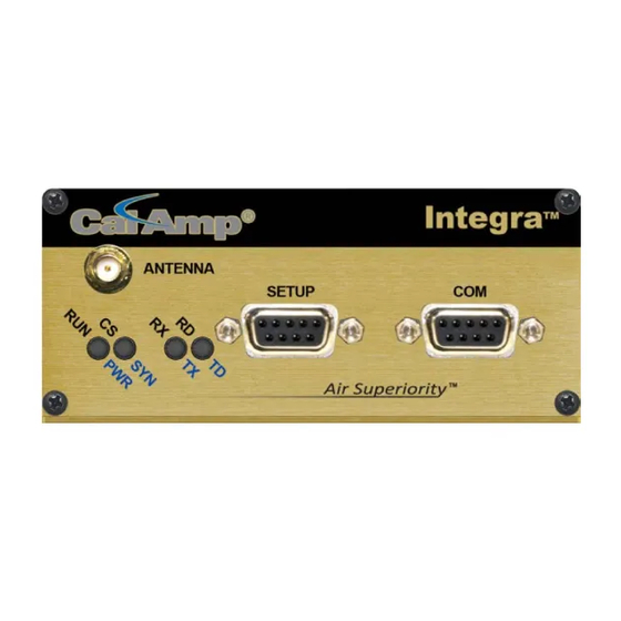
Page 8: Physical Description
PHYSICAL DESCRIPTION Integra-TR consists of a logic PCB (which includes modem circuitry) and a radio module. Each logic PCB and radio module are matched together and characterized in the factory to optimize performance as an intelligent unit. The two boards then slide into the rails of an extruded aluminum case. -
Page 9: Com Port
DTE baud rates from 1200 to 19200 are supported. Integra-TR's are factory set for or 9600 b/s, 8 bits, no parity, and 1 stop bit. Unless required by your operating protocol, we advise restricting port speed to be equal to or less than the RF network speed. -
Page 10: Setup Port
For DTE that lack RTS control, Integra-TR can operate in DOX (Data Operated Transmit) mode with only Transmit Data, Receive Data and Ground. This 3-wire interface is shown in Figure XX. Figure 3 - 3-wire Interface 1.4.4 SETUP PORT The Setup port uses a DE-9 female connector configured as DCE. Signals are described in Table 3. -
Page 11: Heat Sink
1.5.1 HEAT SINK The rear panel heat sink is essential for proper operation of the Integra-TR transmitter. The unit must be mounted in a location that permits free air circulation past the heat sink. Cooling will be best if the fins are vertical. -
Page 12: Transceiver Identification
ACCESSORIES AND OPTIONS Table 5 - Accessories Part Number Accessory 250-4008-001 Integra-TR Field Programming Kit includes software, technical manual on CD ROM with programming cable (Part Number 697-4008-408) 697-5000-101 SMA to Type N-Male Adapter Cable 002-4008-100 Start-Up Disc includes Field Programming Software, Manual and Quick Start Guide... -
Page 13: Specifications
Supply Voltage 10 - 16 VDC maximum (nominal 13.3) Fuse protected against reverse voltage RX Current Drain at 13.3 VDC < 270 mA (with a terminal connected to Integra-TR COM port) TX Current Drain at 13.3 VDC <2.6 A Power Saving Mode Current Drain <20 mA... - Page 14 Modem/Logic Operation Simplex/half duplex Data Bit Rates (b/s) 25 kHz: 4800/9600/19200; 12.5 kHz: 4800/9600 Modulation Type DRCMSK (Differential Raise-Cosine Minimum Shift Keying) RTS/CTS Delay (RTS mode) 4 ms Addressing 10 bit station address, 1 bit station type (master / remote) 12.5 kHz @ 9.6 kbps: -104 dBm, 1x10⁻⁶ @ 1.4 µV Bit Error Rate (BER) 25 kHz @ 4.8 or 9.6 kbps: -107 dBm, 1x10⁻⁶ @ 1.0 µV...
-
Page 15: Getting Started
GETTING STARTED It is easy to set up an Integra-TR network to verify basic unit operation and experiment with network designs and configurations. An RX/TX antenna is required for basic operation. It is important to use attenuation between all demo units to reduce the amount of signal strength in the test environment. -
Page 16: Installing The Fps
Integra-TR FPS is available on the Start-Up CD-ROM as a .zip file. You may also visit the Download Library available from the The Field Programming Software for the Support Menu at www.calamp.com for the most current version available. Integra is the professional service installer interface. The Field Programming Software should never be made available to unqualified personnel. -
Page 17: Using The Fps
IntegraTR application. STEP 2 From the Integra-TR Programmer screen, click on the Program button in the upper left corner. This will bring up the Program Parameters screen and display the option to automatically configure the device as a Remote or Master. -
Page 18: Network Applications
RF PATH AND COMMUNICATIONS RANGE Integra-TR is designed for use over distances up to 30 miles + (50 km) depending on terrain and antenna system. To assure reliable communications, the RF (radio frequency) path between stations should be studied by a competent professional who can determine what antennas are required and whether or not a repeater is needed. -
Page 19: Point-To-Multipoint System
If a simplex radio network is used (i.e. a single frequency for all stations), we recommend that the master Integra-TR be set to “master”, the remotes to “remote” and all units to “selective” data delivery. This will prevent remote stations from hearing each other's responses. - Page 20 Figure 10 - Point-to-Multipoint System (full-duplex repeater) Page | 19...
-
Page 21: Extending A Landline (Tail Circuit)
3.2.3 EXTENDING A LANDLINE (TAIL CIRCUIT) Integra-TR may be used to extend a landline circuit (giving access to difficult locations, etc.). This type of connection is called a “tail circuit” and is shown in Figure 11. The tail circuit assembly may be used in any of the network types described in the preceding sections. -
Page 22: Integra-Tr Field Programming Software
Firmware updates: The Integra-TR firmware resides in flash EPROM and is designed to allow field updates. Updates are done using a PC connected to the Integra-TR but do not require opening the unit. Updates should be coordinated by the Technical Service team. -
Page 23: Edit Menu
Save Data File Save Data File As Open Integra Data File Figure 14: Integra-TR Programmer – File Menu EDIT MENU From the primary Programmer screen, the Edit Menu offers the following options: Setup Modem/Radio Parameters Version Request ... -
Page 24: Setup Modem/Radio Parameters
To access the Setup Modem/Radio Parameters screen, use the Parms Icon. You may also access this screen from the Edit menu. Setup Modem/Radio Parameters allows the user to view and edit Integra-TR’s programmable parameters. Programming parameters can be stored in a data file with the .DAT file extension. Programmable parameters are used by the Read/Program Parameters screen for programming into nonvolatile memory (see This section describes the Modem Operating Parameters shown in Figure 15. - Page 25 Select Enabled/Disabled. When enabled, the unit is in low power consumption (approximately 15 mA). In Sleep Mode, the Integra-TR cannot detect the presence of a carrier. Only asserting RTS on the COM or Setup ports will wake the unit. It is ready to receive and decode data within 45 to 65 mS (dependent on Integra model and temperature) after wake-up.
- Page 26 This field extends transmitted synchronization time when the unit is used in a network with repeaters. The default is 5 mS and the range is 0 to 100 mS in 5 mS intervals. Add 10 mS for each Repeater an Integra-TR communicates through in a network (dependent on user’s protocol).
- Page 27 Port. The optional mode is RTS in which the unit begins transmission only when the RS-232 RTS input pin of the COM Port is raised and continues transmitting until the RTS is dropped. Selecting RTS also activates the switched option in DCD control. Figure 19: Integra-TR Control Signal Timing Page | 26...
- Page 28 DCD Control Radio button selection for RS-232 DCD (Data Carrier Detect) mode • Active – DCD is always asserted • Switched – follows the radio carrier and data sent to DTE DTE Baud Rate Select 1200/2400/4800/9600/19200 to configure the port speed of the COM Port DTE Data Format ...
- Page 29 4.3.1.2.2.1 EXTERNAL I/O 1 (GREEN) These radio buttons select configuration of Pin 3 on the Power - I/O Connector (green wire): Analog Input An option on units not equipped with the cooling fan option - can be used to monitor an external voltage (0 to 10 volts).
- Page 30 Digital Output This connection can be used to control the open-collector transistor on the connector. The open-collector output can sink a maximum current of 40 mA when the modem board rev is 0 and 100 mA when the modem board rev is 1.
- Page 31 Radio Display the model of the connected radio device Range Displays the range number of the connected radio device Channel Bandwidth Displays the channel bandwidth of the connected device: Half-channel (12.5 kHz) or Full-channel (25 kHz) Transceiver Type ...
- Page 32 Selected Channel This field allows the user to choose a selected channel pair for receiving and transmitting. Allowable entries are 1 to 16. The selected channel will be used if Channel Select 1 and Channel Select 2 are NOT selected. (COM/Analog Tab).
-
Page 33: Version Request
4.3.2 VERSION REQUEST From the Programmer Window, Select Edit – Version Reset to display the following information about the connected device. Integra-TR: displays the Modem Firmware Version Number) Serial Number: displays the serial number of the modem module ... -
Page 34: List Information
4.3.5 PROGRAM COMMENT/ID From the Programmer Window, Select Edit – Program/Comment ID to access the Program Comment/ID configuration screens. This utility is particularly useful if the Integra-TR being programmed was cloned from another unit (See Figure 25). Page | 33... -
Page 35: Program Parameters
From the Programmer Window, Select Edit – Program Parameters. Program Parameters allows the user to program the currently loaded programmable parameters to the Integra-TR (the ID Number, Comment and Remote/Master settings are extracted from the fields on the screen). This option can be used for programming the same Data File (.DAT) into multiple modems (if .dat file is imported into the parameters field, the Short ID, Comment and Remote/Master settings will be... -
Page 36: Read Parameters
4.3.7 READ PARAMETERS From the Programmer Window, Select Edit – Read Parameters. The Read Parameters function tells the Integra-TR to pull the parameters that are currently programmed in the Integra-TR. To view these parameters, click the Parms Icon after running the Read utility. -
Page 37: Port Settings
Field Programming Software. The programming cable (included in the Programming Kit - DRL part number 250-4008- 001) is connected from the Setup Port on the Integra-TR to the PC’s COM port configured as the Primary Port. The Port Settings screen of the Field Programming Software is accessed via the Utilities pull-down menu. - Page 38 Select Yes/No. Enable to assert the DTR (Data Terminal Ready) line of the RS-232 Port when the port is open for the Primary and Secondary COM Ports. Mode Select the communication mode to be used by the Integra-TR. Refer to Table XX for Communication Mode descriptions. Table 7 – Communication Mode Descriptions Mode...
- Page 39 4.4.1.2 ADVANCED PORT SETTINGS Figure 29 – Port Settings Advanced Tab Ignore DCD Before Tx’ing Allows the user to check for an inactive DCD before transmitting. If selected, no data is sent until DCD becomes active DCD Timeout If Ignore DCD Before Tx’ing is selected, DCD Timeout determines the length of time to wait for DCD to become inactive before data is sent.
-
Page 40: Swap Com Ports
DMP Baud Rate Select 1200, 2400, 4800, 9600, 19200, 38400 or 115200 to set the communication speed for Primary and Secondary COM Ports when using the DMP Protocol. DMP is used to talk to the Integra modems through the Setup Port. - Page 41 Figure 30: Port Statistics Screen Baud Rate Displays the current setting for the utilized COM port RTS is an output from the user connected DTE device. This will be checked if active. DTR is an output from the user connected DTE device. This will be checked if active. ...
-
Page 42: Offline Link Test
4.4.4 OFFLINE LINK TEST From the Programmer Window, Select Utilities – Offline Link Test The Offline Link Test is used to test the link between two units – the local unit connected to the PC and a remote unit. Blocks of data are transmitted to the remote unit and the remote unit decodes and returns them. The transmitted and received data blocks are compared and the ratio of the results is calculated. -
Page 43: Offline Diagnostics
Save Allows the user to save the current Offline Link Test results to a file. The Offline Link Test returns the following statistics: Blocks Tx’ed to Remote Displays the number of data blocks transmitted to the remote unit. Responses from Remote ... - Page 44 Figure 32: Offline Diagnostics Screen Offline Diagnostic parameters include the following: Unit ID The Short ID of the unit sending diagnostics. RSSI Level Received Signal Strength Indication in dBm. Battery Voltage Supply voltage Temperature Internal case temperature in Celsius. Forward Power ...
- Page 45 XCVR Status Displays the status of the transceiver. Tx Timeout A request for a remote unit to transmit causes the unti to transmit on the programmed transmit frequency until the Tx Timeout Timer expires. Program the Tx Timeout Timer in the Setup Modem/Radio Parameters/Radio Tab. Progress ...
-
Page 46: Online Diagnostics
Remote ID Allows the user to send diagnostic commands to any specific remote unit and obtain its diagnostic information. The Remote ID is selected from the list of Remote IDs set up in the Diagnostic IDs and Alarms screen. Diagnostic Select Selected Remote ID ... - Page 47 interfaced with will output Online Diagnostics as they are received. Using Online Diagnostics does not require suspension of network operation. Online Diagnostics are subject to alarm conditions defined in Section XXX Diagnostic IDs and Alarms. When Online Diagnostics are received and a diagnostic field falls outside the alarm limits, value X will be designated as less than < or greater than >...
- Page 48 RevP Reverse Power displays the approximate measure of reverse (reflected) power of the unit transmitting the diagnostics. This is represented as “Good” if the reverse power is within acceptable limits and is represented as “Bad” if the reverse power is too high. The threshold is set to approximately 1/4 the forward power. Remote RSSI ...
-
Page 49: Diagnostic Ids And Alarms
4.4.7 DIAGNOSTIC IDS AND ALARMS From the Programmer Window, Select Utilities – Diagnostics IDs and Alarms The Diagnostics IDs and Alarms screen allows the user to set up the ID List for use with the Offline Link Test, and Offline and Online Diagnostics as well as Alarms for use with Online Diagnostics. -
Page 50: User Test
Low/High RSSI Enter the high and low limits for acceptable RSSI levels (in dBm). Low/High Temp Enter the high and low limits for acceptable temperature levels (in Celsius). Low/High Batt Enter the high and low limits for acceptable battery voltage levels (in volts). Low/High Fwd Pwr ... - Page 51 Reverse Power Reverse power in watts or dBm. External I/O 1 Voltage on the External I/O 1 Input from the Power - I/O Connector (in volts). External I/O 2 Voltage on the External I/O Input from the Power - I/O Connector (in volts). Preamble Good ...
-
Page 52: Packet Test
4.4.9 PACKET TEST From the Programmer Window, Select Utilities – Packet Test The Packet Test allows the user to simulate a Host/Remote polling environment. The Host will send out a packet to the Remote and the Remote will reply to the Master with the same packet information. This test is useful for testing the modem link. - Page 53 Overall % Shows the percentage of Host received packets versus Host transmitted packets # of Packets to Send A programmable number to tell the Host how many data packets to send to the Remote. After the programmed number of data packets are sent, the transmission will automatically stop Bytes of Data/Packet ...
-
Page 54: Array Test
4.4.10 ARRAY TEST From the Programmer Window, Select Utilities – Array Test. The Array Test utility is used to send programmable length test packets. The packets are built using one of four possible patterns. For pattern descriptions, refer to Section XX. Figure 37: Array Test Screen Packets Tx’ed ... - Page 55 4.4.10.1 PATTERN DESCRIPTIONS ASCII Pattern The ASCII Pattern Packet are 58 characters in length and have a sequence number at the beginning of each string, starting at 000, incrementing to 999 and wrapping around to 000 again. The pattern used to build the packets should have the following format (in ASCII): 000 ABCDEFGHIJKLMNOPQRSTUVWXYZabcdefghijklmnopqrstuvwxyz 001 ABCDEFGHIJKLMNOPQRSTUVWXYZabcdefghijklmnopqrstuvwxyz...
-
Page 56: Ping Test
Random Binary Pattern Random Binary Pattern is 16 characters in length and contains random binary data. 4.4.11 PING TEST From the Programmer Window, Select Utilities – Ping Test. The PING Test is used to simulate a Host/Remote polling environment. The Master sends out a packet to the Remote and the Remote replies to the Master with the same packet information. - Page 57 ASCII Pattern The packets will be 52 characters in length. The pattern used to build the packets will have the following format (in ASCII): ABCDEFGHIJKLMNOPQRSTUVWXYZabcdefghijklmnopqrstuvwxyz ABCDEFGHIJKLMNOPQRSTUVWXYZabcdefghijklmnopqrstuvwxyz ABCDEFGHIJKLMNOPQRSTUVWXYZabcdefghijklmnopqrstuvwxyz ASCII Number Pattern The packets will be 48 characters in length. The pattern used to build the packets will have the following format (in ASCII): 00 11 22 33 44 55 66 77 88 99 AA BB CC DD EE FF 00 11 22 33 44 55 66 77 88 99 AA BB CC DD EE FF...
-
Page 58: Ascii/Hex Terminal
Start Begins the Ping Test. Stop Stops the Ping Test. Save Offers the user the option to save the information received from the test. Close Closes the Ping Test window. 4.4.12 ASCII/HEX TERMINAL The ASCII and Hex Terminal Screens are accessed from the Utilities pull-down menu and allow the user to select an ASCII, Hexadecimal TCP Socket or UDP Socket Terminal Screen for the Primary and Secondary COM Ports (configured in the Port Settings screen - see Section 4.4.1) Data is sent according to the port configuration set up in the Port Settings screen. - Page 59 Secondary The Secondary ASCII Terminal screen allows the user to send and receive ASCII data on the Secondary COM Port (set up in the Port Settings screen). TCP Socket The TCP Socket Terminal screen allows the user to send and receive ASCII data over a TCP connection. UDP Socket The UDP Socket Terminal screen allows the user to send and receive ASCII data over a UDP connection.
-
Page 60: Program Code Menu
Read Boot Code Version, Select Firmware File (allows the user to select the file to program the firmware in the Integra-TR) or Upgrade Boot Code file. Selecting one of these options opens a standard navigation window to select the desired file. -
Page 61: Network Optimization
CHECK TIMER SETTINGS Polling protocols issue a poll and wait a certain time for a response. Integra-TR adds a short amount of delay to each poll and response (typically in the order of 60 to 70 ms). Timer settings that are too short may cause erroneous indication of missed polls, in which case the application may retry or continue to cycle, ignoring the missed station. -
Page 62: Interpreting Power Readings
Some representative performance values for 9600 b/s operation are given below. These values assume that the units are correctly aligned and installed in a quiet location. Environments with high electrical or RF noise levels will require an increase (less negative) in the numbers shown to achieve a given level of reliability. -100 dBm Approximately 50% reliability. -
Page 63: Definitions
The Communications Port of the wireless device. This port is configured as DCE and is designed to connect directly to DTE. Clear to Send. An RS-232 output signal from Integra-TR indicating that it is ready to accept data (used in RTS mode). - Page 64 CalAmp delivers cost-effective high quality solutions to a broad array of customers and end markets. CalAmp is the leading supplier of Direct Broadcast Satellite (DBS) outdoor customer premise equipment to the U.S. satellite television market. The Company also provides wireless data communication solutions for the telemetry and asset tracking markets, private wireless networks, public safety communications and critical infrastructure and process control applications.
Need help?
Do you have a question about the Integra-Tr and is the answer not in the manual?
Questions and answers