
Related Manuals for CalAmp SMC-GPRS- Series


Summary of Contents for CalAmp SMC-GPRS- Series
- Page 1 L a n d C e l l S M C E m b e d d e d W i r e l e s s M o d e m G S M G P R S U n i v e r s a l S o c k e t User Manual 001-0004-829 Rev01;...
- Page 2 REVISION HISTORY Rev00 Released 10/2009 Updates related to Rev02 Rev01 11/2011 hardware changes.
-
Page 3: Table Of Contents
TABLE OF CONTENTS SECTION 1 - PREFACE ................... 5 Copyright Notice ....................5 Modem Use ......................5 Interference Issues ....................5 Mobile Application Safety ..................6 Related Documents ....................6 SECTION 2 - ABBREVIATIONS ................7 SECTION 3 - PRODUCT OVERVIEW ................8 Module Identification ..................... - Page 4 TABLE OF CONTENTS SECTION 10 - AT COMMAND REFERENCE .............. 34 AT Command Types .................... 34 Command Line Syntax ..................34 Result Codes ...................... 35 Configuration Commands ..................35 Status Control Commands ................... 37 Serial Interface Control Commands ............... 38 Security Commands ....................
-
Page 5: Preface
Copyright Notice ©2011 CalAmp. All Rights Reserved. This manual covers the operation of the CalAmp SMC-GPRS Embedded Wireless Modem. Specifications described are typical only and are subject to normal manufacturing and service tolerances. CalAmp reserves the right to modify the equipment, its specification or this manual without prior notice, in the interest of improving performance, reliability or servicing. -
Page 6: Mobile Application Safety
Mobile Application Safety Do not change parameters or perform other maintenance of the SMC-GPRS while driving. Road safety is crucial. Observe National Regulations for cellular telephones and devices in vehicles. Avoid potential interference with vehicle electronics by correctly installing the SMC-GPRS. -
Page 7: Abbreviations
Abbreviation Description Access Point Name CDMA Code Division Multiple Access Circuit Switched Data Clear to Send Data Carrier Detect Data Communication Equipment Data Terminal Equipment Dial-Up Network EDGE Enhanced Data rates for Global Evolution GPRS General Packet Radio Service Global Positioning System Global System for Mobile communication IMEI International Mobile Electronic Identity... -
Page 8: Product Overview
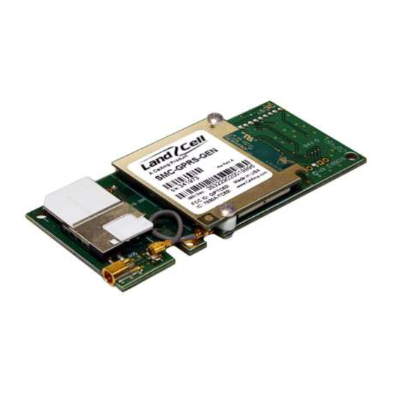
IMEI: The International Mobile Equipment Identifier of the cellular module in decimal format. General Description The LandCell SMC-GPRS embedded wireless modem from CalAmp is a versatile, cost-effective wireless communications device designed for the industry-standard universal socket. Quad- band GSM/GPRS offers compatibility with cellular networks around the world. -
Page 9: Smc Module Description
SMC Module Description Top side reference Fig. 2.1 SMC-GPRS Top Side SMC-GPRS top side components: 1. Power: Green LED indicating cell module power on. 2. DCD: Red LED indicating Data Carrier Detect from cellular network. 3. RF (antenna): MMCX socket, primary antenna connection. 4. -
Page 10: Bottom Side Reference
Bottom side reference Fig. 2.2 SMC-GPRS Bottom Side SMC-GPRS bottom side socket pins: 1. VCC/GND pins 2. –Reset/GND pins 3. SERIAL pins Figure 2.3 SMC Pins, Top View 001-0004-829 Rev01 Page 10 of 73... -
Page 11: Pin Descriptions
Pin Descriptions Pin # Description Name Type This signal is used to force a reset procedure by providing a low level for at least 10 ms. Data stored in volatile memory will be lost. -RESET Input This line must be driven by an open drain or open collector. If unused, keep line open. -
Page 12: Development/Test Board Interface
Development/Test board The Development/Test board is required to interface the SCM-GPRS modem to a standard RS232 serial connection. The SMC test board also supplies the SMC-GPRS modem with the required +5VDC supply voltage from an externally supplied 10 to 28 VDC power source, +12VDC typical. Figure 4.1 SMC modem with DK test board SMC-GPRS test board components: 1. -
Page 13: Accessories
RS-232 Serial Port Integration Parameters Table 4.2 provides the serial cable design information for the SMC-GPRS using the DK test board. Table 4.2 Standard RS-232 DE-9 Pin out Name Direction Description «— Carrier Detect «— Receive Data —» Transmit Data —»... -
Page 14: Getting Started Using The Smc Test Board
This section describes the use of the SMC test board to set up the SMC modem for internet access using HyperTerminal and a dial-up network connection (DUN). Please refer to Appendix B for details on setting up a modem driver for a DUN connection. Connecting Up the SMC Test Board Connect the Power cable, RS232 cable, Antenna cable to the SMC test board as shown in Figure 5.1. -
Page 15: Verify Smc Modem Connectivity
Verify SMC Modem Connectivity Power on the SMC test board (+12VDC typical) and observe the HyperTerminal window for ^SYSSTART , indicating the SMC modem successfully powered on. Figure 5.2 HyperTerminal screen responses The ATI command prints the cell module product information. If you get an Error or no communication, verify the modem is connected to the proper COM port and powered on. -
Page 16: Define The Packet Data Protocol (Pdp) Context
Confirm that the SIM‘s PIN has been authenticated by the network using the AT+CPIN? command. The reply should read ―+CPIN: READY‖. See Section 6 for SIM related information if ―READY‖ does not display. Verify good signal strength with the AT+CSQ command. A typical reply is +CSQ 25, 99. The first number is signal strength and ranges from 0 to 31 (the higher the number, the stronger the signal). -
Page 17: Connect Using The Dial-Up-Network Connection
Connect using the Dial-Up-Network Connection Go to the Network Connections screen and double click on the newly created Dial-Up connection (i.e. SMC-GPRS). When the connect window appears, set the username and password as defined for your carrier (usually blank). Enter the phone number as *99***1# and click the Dial button. 001-0004-829 Rev01 Page 17 of 73... - Page 18 The modem will attempt to connect to the provider network. If the configured baud rate for the COM port, the modem, and the DUN do not match, the DUN will not be able to talk to the modem properly and you will get a hardware error message. Otherwise the DUN will contact the cellular network and authenticate the user on the network.
- Page 19 Right click on the connected Dial-Up connection icon in the task bar and select the Details tab. The status of the connection will be displayed, including the IP address assigned by the carrier network. 001-0004-829 Rev01 Page 19 of 73...
-
Page 20: Sim Card Specific Information
The SIM card can be used to store a Personal Idetification Number (PIN) to authenticate users on the network. The AT+CPIN write command can be used to enter one of the passwords listed below. The read command can be used to check whether or not the ME is waiting for a password, or which type of password is required. -
Page 21: What To Do If Pin Or Password Authentication Fails
What to do if PIN or password authentication fails? PIN1 / PUK1: After three failures to enter PIN 1, the SIM card is blocked (except for emergency calls). +CME ERROR: 12 will prompt the client to unblock the SIM card by entering the associated PUK (= PIN Unblocking Key / Personal Unblocking Key). - Page 22 SIM locks: These are factory set locks, such as "PF", "PN", "PU", "PP", "PC". An 8-digit unlocking code is required to operate the mobile with a different SIM card, or to lift the lock. The code can only be obtained from the provider. Failure to enter the password is subject to the same timing algorithm as the Master Phone Code (see Table above).
-
Page 23: Call Setup Information
This section provides a brief look at setting up variuos call scienerios using the SMC-GPRS modem with the SMC Development/Test board and HyperTerminal. In general, each call scienerio requires a set of initialization commands to set up the SMC modem for the specific call type. See related documents [1] and [2] for more detailed descriptions and examples for all call types. -
Page 24: Csd Incoming Calls
Select ATV0 to set the short format (numeric code) or ATV1 to set the long format (verbose code) of result codes. In case of using the command without parameter the value will be set to 0. Generally, only AT+CBST=0 (auto bauding) and AT+CBST = 7 (9600 bps, [V.110]) are supported and provide reliable performance. -
Page 25: General Packet Radio Service (Gprs)
General Packet Radio Service (GPRS) Before proceeding, be sure the cellular account SIM is provisioned with GPRS data services and all necessary initialization commands have been executed. The module must then be attached to the GPRS service, allowing the device to be accessable by the network, but no data transmission is yet possible. -
Page 26: Define The Gprs Context
Define the GPRS Context Exact settings of GPRS context and Quality of Service Profiles are provisioned by the network provider and must be requested before defining the GPRS context. Every PDP context has a context identifier <cid>. The context identifiers are numbered sequentially and have to start with value 1. -
Page 27: Short Message Service (Sms)
Short Message Service (SMS) SMS is a service to transfer short messages between a GSM Mobile Stations (MS) and an Short- Message-Entity (SME) via a Service Center (SC). SMC modems support two modes: text mode and Protocal Data Unit (PDU) mode. The minimal requirements to send a short message are: - Service center address of the provider - Destination address - Content of the message... -
Page 28: Writing Sms
If you want to receive cell broadcast messages activate the URC presentation for CBS with AT+CNMI and subscribe to a CBS channel with AT+CSCB. The AT^SM20 command specifies different modes of responses returned when sending and writing short messages: AT^SM20=,0 causes the ME return "+CMS ERROR: <err>" when writing or sending of short messages fails. -
Page 29: Internet Services
Internet Services The modem has an embedded TCP/IP stack that is driven by AT commands and enables the host application to easily access the Internet. The advantage of this solution is that it eliminates the need for the application manufacturer to implement their own TCP/IP and PPP stacks, thus minimizing cost and time to integrate Internet connectivity into a new or existing host application. - Page 30 The TCP/IP stack of TC63i supports using several service profiles at the same time, provided all of them are running on the same connection profile. For example, it is possible to download files from an FTP server, while sending and receiving emails at the same time. GPRS connections established over the Dial-Up Network do not use the embedded TCP/IP stack of TC63i and can be active at the same time.
-
Page 31: Smc Modem Module Profiles
In addition to the default profile, you can store an individual one with AT&W. To alternate between the two profiles enter either ATZ (loads user profile) or AT&F (restores factory profile). NOTE: Every ongoing or incoming call will be terminated. Table 8.1: Profile Commands Returns the current parameter setting. -
Page 32: Common At Command Reference Guide
Below you will find a reference guide of the AT commands most commonly used in day-to-day operation of the modem. Table 9.1: Common AT Commands Command Description Configuration Commands AT&F Set all current parameters to manufacturer defaults AT&V Display current configuration AT&W Stores current configuration to user defined profile Extended Configuration Settings... - Page 33 Network Service Commands Signal Quality AT+CSQ Example response; +CSQ: 25,0 has an RSSI of -63 dBm Cell Info Table Example response: GPRS Monitor BCCH G PBCCH PAT MCC MNC NOM TA RAC # Cell # 0637 1 - 234 05 00 0B BCCH - ARFCN of BCCH carrier G - GPRS status:...
-
Page 34: At Command Reference
All modem functions are controlled using the same industry-standard AT commands that are used to control landline modems. A knowledge of all these commands is not required by most users, but are provided here as a reference. AT Command Types There are several types of AT commands as defined in the following list;... -
Page 35: Result Codes
Result Codes After issuing a command, a result code will typically be displayed on the screen to inform you if the command was successful, unsuccessful, improperly formatted, etc. When in the command mode, thirteen possible result codes may be returned. The result codes can be set to display as either digits or words by accessing the Verbose command, ATV. - Page 36 3 - CONNECT <text> result code returned, dial tone detection is disabled, busy detection is enabled. 4 - CONNECT <text> result code returned, dial tone and busy detection are both enabled. Set CONNECT result code format: AT\V 0 - CONNECT <text> result code returned without RLP trailer. 1 - CONNECT <text>...
-
Page 37: Status Control Commands
Status Control Commands The AT Commands described in this section allow the external application to obtain various status information from the modems cellular module. Table 10.4: Status Control Commands Command Description Mobile Equipment Event Reporting: AT+CMER=<mode>,0,0,<ind>,0 Mode: 0 - Discard "+CIEV" and "^SLCC" URCs. 1 - Discard "+CIEV"... -
Page 38: Serial Interface Control Commands
Serial Interface Control Commands The AT Commands described in this section allow the external application to determine various settings related to the modems's serial interface. Table 10.5: Serial Interface Control Commands Command Description Flow control: 0 - Disable flow control 1 - XON/XOFF software flow control 2 - Only CTS by DCE (TA) AT\Q... -
Page 39: Security Commands
Set TE-TA local rate reporting: 0 - Disables reporting of local port rate AT+ILRR 1 - Enables reporting of local port rate 300, 600, 1200, 2400, 4800, 9600, 14400, 19200, 28800, 38400, 57600, 115200, 230400, 460800 rates supported Set fixed local rate: AT+IPR 300, 600, 1200, 2400, 4800, 9600, 14400, 19200, 28800, 38400, 57600, 115200, 230400, 460800 rates supported... -
Page 40: Identification Commands
Identification Commands The AT Commands described in this section allow the external application to obtain various identification information related to the modem and linked entities. Table 10.7: Identification Commands Command Description The execute command delivers product information text. The 'Revision' information consists of the following parts: Version xx and variant yy of software release. - Page 41 Set number of seconds to wait for connection completion: ATS7 =000 to 060 Set number of seconds to wait for comma dialing modifier: ATS8 DCE does not pause when "," encountered in dial string =1 to 255 Number of seconds to pause Set disconnect delay after indicating the absence of data carrier: ATS10 =001 to 254 Number of tenths of seconds of delay...
-
Page 42: Network Service Commands
Single Numbering Scheme: The command enables the ME to accept incoming calls when no bearer capability information is provided with the call, e.g. single numbering scheme calls or calls originitating from analog devices. =0 Voice: Each call received without bearer element is assumed to be speech AT+CSNS =2 Fax: Each call received without bearer element is assumed to be an incoming fax. - Page 43 AT^SOPS Extended Operator Selection similar to At^COPS. Network registration: The read (?) command serves to verify the network registration status of the 0 - Not registered, ME is currently not searching for new operator and user intervention is required. Yet, emergency calls can be made if any network is available.
- Page 44 Monitor neighbour cells: The command supplies information of up to six neighbour cells. There are two ways to retrieve the information: once on request by using the execute AT^MONP command or automatically every <period> seconds by using the write command. To stop the periodic presentation type "AT" or "at". =1 to 254 periods in seconds GPRS Monitor: The command supplies GPRS specific cell information.
-
Page 45: Internal Internet Service Commands
Internal Internet Service Commands A brief description of the internet service commands are provided in Table 10.10. For futher information, refer to the Cinterion TC63i AT Command Set document available from Cinterion [2]. Table 10.10: Internet Service Commands Command Description Internet Connection Close: AT^SICC The write command releases a connection opened with AT^SICO and restores... -
Page 46: Gprs Commands
GPRS Commands This Section describes AT Commands that a TE (Terminal Equipment, e.g. an application running on a controlling PC) may use to control the modem acting as a GPRS Mobile Termination (MT). A brief description of the GPRS commands are provided in Table 10.11. For futher information, refer to the Cinterion TC63i AT Command Set document available from Cinterion [2]. - Page 47 Automatic response to a network request for PDP context activation: The test command returns the values of <n> supported by the MT as a compound value. The write command disables or enables an automatic positive response (auto- answer) to the receipt of a Request PDP Context Activation message from the network.
- Page 48 GPRS network registration status: The read command returns the status of result code presentation and an integer <stat> which shows whether the network has currently indicated the AT+CGREG registration of the MT. The write command controls the presentation of an unsolicited result code "+CGREG: <stat>"...
-
Page 49: Short Message Service (Sms) Commands
Request GPRS or GPRS IP service: This command causes the MT to perform whatever actions are necessary to establish a communication between the TE and the external PDN. Request GPRS service: ATD*99**<L2P>*<cid># L2P: blank – non PPP ―PPP― - layer 2 protocol PPP ―1―... -
Page 50: Sim Related Commands
AT^SCMS Send concatenated SMS messages AT^SCMW Write concatenated SMS messages to memory AT^SLMS List SMS Memory Storage AT^SMGL List SMS messages from preferred store without setting status to REC READ AT^SMGO Set or query SMS overflow presentation mode or query SMS overflow AT^SMGR Read SMS message without setting status to REC READ AT^SSCONF... -
Page 51: Hardware Related Commands
Hardware Related Commands The AT Commands described in this section are related to the modems's hardware interface. A brief description of hardware related commands are provided in Table 6.14. For futher information, refer to the Cinterion TC63i AT Command Set document available from Cinterion [2]. Table 10.14: Hardware Related Commands Command Description... -
Page 52: Factory Default At Command Values
Factory Default AT Command values Table 10.15: AT Command Factory Defaults Configuration Commands <n>=0 <value>=1 <value>=4 AT\V <value>=1 AT+CFUN <fun>=1 AT+CMEE <errMode>=0 AT+CSCS <chset>="GSM" AT^SM20 <CallMode>=1, <CmgwMode>=1 Status Control Commands AT+CMER <mode>=0, <keyp>=0, <disp>=0, <ind>=0, <bfr>=0 AT+CIND <mode>=1 ATS18 <n>=0 Serial Interface Control Commands AT\Q <n>=0... - Page 53 Short Message Service (SMS) Commands AT+CMGF <mode>=0 AT+CNMI <mode>=0, <mt>=0, <bm>=0, <ds>=0, <bfr>=1 AT+CSDH <show>=0 AT+CSMP <fo>=17, <vp>=167, <dcs>=0, <pid>=0 AT+CSMS <service>=0 AT^SMGO <n>=0 AT^SSCONF <ra>=0 AT^SSDA <da>=0 AT^SSMSS <seq>=0 SIM related Commands AT^SCKS <mode>=0 AT^SSET <n>=0 Hardware related Commands AT^SCTM <n>=0 AT^SSPI...
-
Page 54: Specifications
Product specifications are subject to change without notice. General Specifications Interface Connectors: Universal Socket Connectivity LED Indicators: Power & DCD Antenna Interface: Primary Antenna: MMCX, female, 50 ohms Size: 3.150 x 1.375 x 0.527 in. Weight: 0.8 oz. Power Input: 5VDC ±0.25VDC;... -
Page 55: Data Transmission Specifications
Data Transmission Specifications Internet Services TCP, UDP, HTTP, FTP, SMTP, POP3 GPRS Data Transmission GPRS Class 12 Mobile Station Class B PBCCH support Coding scheme CS 1-4 CSD Data Transmission Up to 14.4 kbps V.110 Non-transparent mode USSD support Specifications for SMS Point-to-point MO and MT SMS cell broadcast Text and PDU mode... -
Page 56: Mechanical Specifications
Mechanical Specifications The following section describes in detail the exterior dimensions of the SMC-GPRS. All of the drawings below are the approximate actual size. The drawings may be used as layout reference, but it is advised that a physical comparison be made to the modem before proceeding with the mounting process. -
Page 57: Service And Support
Product Warranty, RMA and Contact Information CalAmp guarantees that every SMC-GPRS Cellular Modem will be free from physical defects in material and workmanship for one (1) year from the date of purchase when used within the limits set forth in the Specifications section of this manual. The manufacturer's warranty statement is available in Appendix 1. -
Page 58: Power Supply Issues
– – Power Supply Issues Because of its high current consumption during transmission, power supply design for the SMC-GPRS modem should be focused on the transmitting mode (dedicated mode). More information can be found in related document [3]. Power Consumption for GSM/GPRS Cell Module Due to the maximum RF power levels of approx. -
Page 59: Smc-Gprs Power Supply Requirements
Power Losses and Voltage Drops for GSM/GPRS Cell Module The cell modules are specified to operate with specific voltage supplies. Voltage supplies may range from 3.2V to 4.5V as measured on the module‘s power connector. To be on the safe side, it should be assumed that the voltage drop during the TX burst does not exceed 400mV. - Page 60 SMC-GPRS Power Supply Considerations Ideally, the external 5VDC supply should be able to provide the 1.4A current required by the SMC- GPRS modem when the TX bursts occur. When this is not a practical design alternative, a mix between a linear regulator and capacitor supply may be an alternative approach. Figure 3 shows the basic block diagram.
-
Page 61: Appendix B - C R E A T I N G A D I A L - U P N E T W O R K I N G C O N N E C T I On
– – Windows XP Add Standard Windows Modem 001-0004-829 Rev01 Page 61 of 73... - Page 62 001-0004-829 Rev01 Page 62 of 73...
- Page 63 001-0004-829 Rev01 Page 63 of 73...
- Page 64 001-0004-829 Rev01 Page 64 of 73...
-
Page 65: Configuring The Modem
Configuring the Modem 001-0004-829 Rev01 Page 65 of 73... -
Page 66: Create A Dial-Up Networking (Dun) Connection
Create a Dial-Up Networking (DUN) Connection 001-0004-829 Rev01 Page 66 of 73... - Page 67 001-0004-829 Rev01 Page 67 of 73...
- Page 68 001-0004-829 Rev01 Page 68 of 73...
- Page 69 001-0004-829 Rev01 Page 69 of 73...
- Page 70 001-0004-829 Rev01 Page 70 of 73...
- Page 71 001-0004-829 Rev01 Page 71 of 73...
- Page 72 001-0004-829 Rev01 Page 72 of 73...
-
Page 73: Appendix C - W A R R A N T Y S T A T E M E Nt
– – CalAmp warrants to the original purchaser for use ("Buyer") that data telemetry products manufactured by DRL ("Products") are free from defects in material and workmanship and will conform to DRL's published technical specifications for a period of, except as noted below, one (1) year from the date of shipment to Buyer.
Need help?
Do you have a question about the SMC-GPRS- Series and is the answer not in the manual?
Questions and answers