Table of Contents
Advertisement
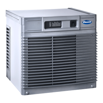
HCC700A, HCC700W, HCD700A, HCD700W Ice Machines
Order parts online
www.follettice.com
Following installation, please forward this manual
to the appropriate operations person.
801 Church Lane • Easton, PA 18040, USA
Toll free (877) 612-5086 • +1 (610) 252-7301
www.follettice.com
Operation and Service Manual
(Self-contained)
00988170R02
Advertisement
Table of Contents

Subscribe to Our Youtube Channel
Related Manuals for Follett HCC700A


Summary of Contents for Follett HCC700A
- Page 1 HCC700A, HCC700W, HCD700A, HCD700W Ice Machines (Self-contained) Order parts online Operation and Service Manual www.follettice.com Following installation, please forward this manual to the appropriate operations person. 801 Church Lane • Easton, PA 18040, USA Toll free (877) 612-5086 • +1 (610) 252-7301 00988170R02 www.follettice.com...
-
Page 3: Table Of Contents
Table of contents Welcome to Follett Corporation Specifi cations Operation Cleaning Weekly exterior care Monthly condenser cleaning Semi-annual evaporator cleaning Service Ice machine operation Water system Electrical system Normal control board operation Error faults Hard error Soft errors Relay output indication Compressor/refrigerant solenoid output Wiring diagram Compressor data... -
Page 4: Welcome To Follett Corporation
Welcome to Follett Follett equipment enjoys a well-deserved reputation for excellent performance, long-term reliability and outstanding after-the-sale support. To ensure that this equipment delivers the same degree of service, we ask that you review the installation manual (provided as a separate document) before beginning to install the unit. Our instructions are designed to help you achieve a trouble-free installation. -
Page 5: Specifi Cations
Specifi cations Electrical Each ice machine requires its own separate circuit with electrical disconnect within 10 ft (6m). Equipment ground required. Standard electrical: HCC700: 208-230/60/1 (6 ft (2m) NEMA 6-15 cord and plug provided) HCD700: 115/60/1 (6 ft (2m) NEMA 5-15 cord and plug provided) Maximum ice machine fuse –... - Page 6 1" (26mm) minimum clearance on sides. The intake and exhaust air grilles must provide at least 160 sq in (1032 sq cm) of open area. Air-cooled model HCC700A ice machines – 18" (458mm) minimum clearance between discharge and air intake-grilles.
-
Page 7: Operation
Operation Cleaning and preventive maintenance (all models) Note: Do not use bleach to sanitize or clean the icemaker. Preventive maintenance Periodic cleaning of Follett’s icemaker system is required to ensure peak performance and delivery of clean, sanitary ice. The recommended cleaning procedures that follow should be performed at least as frequently as recommended, and more often if environmental conditions dictate. - Page 8 Fig. 2 2. Mix 1 gallon (3.8L) 120 F (49 C) water and 7 ounces (198g) (one 7 ounce packet of Follett SafeCLEAN ice machine cleaner, part# 00132001). Locate cleaning cup. Fill until CLEANER FULL light comes on (Fig. 2). CLEANER Note: Do not use bleach to sanitize or clean the FULL...
- Page 9 Fig. 5 5. Mix 1 gallon 120 F (49 C) water and 1.6 ounces (48ml) NU-CALGON IMS-II SANITIZER. Fill until CLEANER FULL light comes on (Fig. 5). Place one Sani-Sponge ™ in remaining sanitizing solution and retain for Step 9. CLEANER Note: Do not use bleach to sanitize or clean the FULL...
- Page 10 Fig. 8 8. Using disposable food service grade gloves, insert dry Sani-Sponge ™ (kit part# 00132068). Next, insert Sani-Sponge soaked in Nu-Calgon IMS-II sanitizer solution (from Step 5). Push both Sani- Sponges down ice transport tube with supplied pusher tube (Fig. 8). Fig.
- Page 11 Fig. 11 11. Place a sanitary (2 gallon or larger) container in bin or dispenser to collect Sani-Sponges and ice for 10 minutes. Collect 5.5 lbs (3kg) of ice from unit. Discard ice and Sani-Sponges (Fig. 11). 11 11...
-
Page 12: Service
Service Ice machine operation (all models) Follett’s ice machine consists of fi ve distinct functional systems covered in detail as follows: • Water system • Electrical control system • Mechanical assembly • Refrigeration system • Bin full The Horizon ice machine overview The Follett Horizon ice machine uses a horizontal, cylindrical evaporator to freeze water on its inner surface. -
Page 13: Water System
Water system The water level in the evaporator is controlled by a feed solenoid and level detecting sensors. Referencing the diagram below, water sensing rods extend down into the reservoir at the end of the evaporator assembly. The system works via electrical conductivity as follows: One of the longest probes is a common. -
Page 14: Electrical System
Electrical system ATTENTION! To prevent circuit breaker overload, wait 15 minutes before restarting this unit. This allows the compressor to equalize and the evaporator to thaw. Normal control board operation The PC board indicator lights provide all the information necessary to determine the machine's status. Green indicator lights generally represent “go”... -
Page 15: Error Faults
Error faults: The Horizon PC board monitors various operating parameters including high pressure, auger gearmotor amperage limits, clogged drain, and low water alarm conditions. There are two types of errors namely “hard” or “soft” . A hard error is one that shuts the machine off and will not allow restart until the reset button is pressed. Even cycling power will not reset a hard error. -
Page 16: Wiring Diagram
Wiring diagram... -
Page 17: Compressor Data
Compressor data Compressor current draw at 115 VAC Air/Water-cooled 60 F/15.5 C 70 F/21.1 C 80 F/26.7 C 90 F/32.2 C 100 F/37.8 C 8.25A 8.12A 8.15A 8.20A 8.89A Locked rotor amps 50A @ 115V Compressor current draw at 208-230 VAC Air/Water-cooled 60 F/15.5 C 70 F/21.1 C... -
Page 18: Mechanical System
Mechanical System Fig. 12 Evaporator disassembly 1. Press CLEAN button to purge evaporator. Turn power OFF when LO WATER lights. 2. Unscrew and disconnect transport tube from louvered docking assembly. Fig. 13 3. Unplug gear motor. Fig. 14 4. Remove shuttle housing: §... - Page 19 Fig. 15 5. Remove gear motor: § Remove gear motor insulation (Fig. 15.1). § Remove 1/4-20 screw, retainer, and spacer (Fig. 15.2). § Remove two 1/2" bolts (Fig. 15.3). § Pull gear motor from auger (Fig. 15.4). § Remove main housing insulation (Fig. 15.5). 6.
- Page 20 Fig. 18 10. Press the lever on the back of the reservoir (Fig. 18.1) to release and remove the solenoid (Fig. 18.2). Fig. 19 11. Remove three screws to remove the reservoir insulation (Fig. 19). Fig. 20 12. Remove three screws to remove the reservoir (Fig. 20).
-
Page 21: Evaporator Reassembly
Fig. 21 13. To remove the rear bushing, place the auger into the evaporator and use it to gently tap and dislodge the rear bushing housing (Fig. 21). Evaporator reassembly Fig. 22 1. Remove and inspect O ring seal. Replace if damaged in any way. - Page 22 Fig. 24 6. Install the reservoir insulation, tube clamp, and solenoid lever with three screws. Install solenoid. Fig. 25 1. Remove and inspect O ring seal. Replace if damaged in any way (Fig. 25.1). 2. Clean O ring groove. Lubricate O ring with petrol-gel and reinstall (Fig.
- Page 23 Fig. 27 6. Install main housing: § Slide main housing onto auger shaft (Fig. 27.1). § Install main housing insulation (Fig. 27.2). § Use an allen wrench to install 3/16" allen screws (3) (Fig. 27.3). Fig. 28 Apply a coat of petrol-gel to the auger shaft. 8.
- Page 24 Fig. 31 12. Insert screwdriver into groover of auger shaft and pry shaft outwards (Fig. 31.1). 13. Insert retainer into groove (Fig. 31.2), ensure that retainer is aligned with hole in spacer. Fig. 32 14. Install screw and tighten (Fig. 32.1). Fig. 33 15.
- Page 25 Fig. 34 16. Install shuttle housing: § Install stream divider (Fig. 34.1). § Place shuttle housing and install two screws CONNECT (Fig. 34.2). BLACK § Plug in shuttle housing connections (Fig. 34.3). ORANGE § Connect vent tube (Fig. 34.4). Fig. 35 17. Plug in gear motor. §...
-
Page 26: Refrigeration System
Refrigeration system Refrigerant pressure data Air-cooled condensers (air) Pressure (psig) discharge/suction 190/31 220/33 250/35 285/37 315/40 Water-cooled condensers (water) Pressure (psig) discharge/suction 215/29 215/31 215/33 215/35 Note: The water control valve is factory set to maintain ± psi discharge pressure @ /21 C water. -
Page 27: Refrigerant Replacement Requirements
Refrigeration charge All service on refrigeration systems must be performed in accordance with all federal, state and local laws. It is the responsibility of the technician to ensure that these requirements are met. Recharging ice machine to other than factory specifi cations will void the warranty. R404A ice machine charge specifi cations Model Charge... -
Page 28: "Bin Full" Detection System
“Bin full” detection system The Follett Horizon ice machine incorporates a unique “bin full” detection system that consists of the shuttle and actuator. The shuttle incorporates a fl ag and switch. Referencing the fi gure below, the normal running position of the fl ag is down, and the switch is closed. When the bin fi lls to the top and ice can no longer move through the tube, the machine will force the shuttle fl ag up, opening the switch and shutting the machine off. -
Page 29: Troubleshooting
Troubleshooting Please see “Service” section for a description of each function. Ice machine disposition Possible causes Corrective action Legend: ON or OFF FLASHING Ice machine is in running 1. Defective compressor. 1. Replace compressor. condition but not making ice. 2. Defective start relay. 2. - Page 30 Ice machine disposition Possible causes Corrective action Legend: ON or OFF FLASHING 6. Ice machine is making ice. 1. Failed water sensors. Processor 1. Clean or replace water probe Excessive water in bin or assumes there is no water when assembly.
- Page 31 this page intentionally left blank...
-
Page 32: Replacement Parts
Replacement parts Order parts online www.follettice.com Evaporator assembly... - Page 33 Order parts online www.follettice.com Reference # Description Part # Tube, ice transport, molded 01006485 Shuttle assembly 01006253 Switch, shuttle 001006261 Compression nozzle 010001734 Compression nozzle, defl ector assembly 01006246 Gasket and retainer 00115600 Auger hardware (includes screw, spacer, retainer) - S/N E03141 and after 01041474 Auger hardware (includes washer and 2 nuts) - before S/N E03141 01006493...
- Page 34 Air-cooled assembly Order parts online www.follettice.com...
- Page 35 Order parts online www.follettice.com Reference # Description Part # Condenser 01006394 Fan motor assembly - 115 V/60 Hz 01006402 Fan motor assembly - 220 V/60 Hz 00130930 Electrical box support 00153635 Cut-out, high pressure safety 00117077 Insulation, bulb, TXV 00106534 Drier 502724 Valve, expansion, thermal (includes insulation and (2) clamps)
- Page 36 Water-cooled assembly Order parts online www.follettice.com...
- Page 37 Order parts online www.follettice.com Reference # Description Part # Electrical box support 00969925 Valve, water regulating 01006329 Union, water 202148 Cut-out, high pressure safety 00117077 Insulation, bulb, TXV 00106534 Drier 502724 Valve, expansion, thermal (includes insulation and (2) clamps) 01006360 Insulation, TXV 502830 Condenser, w/c...
- Page 38 Electrical box Order parts online www.follettice.com...
- Page 39 Order parts online www.follettice.com Reference # Description Part # Cover, electrical box, air/water-cooled 01006386 Board, control, 115 V (includes stand-offs) 01006428 Board, control, 220 V (includes stand-offs) 01006410 Stand-offs (set of 8) 00130906 Capacitor, compressor run - 115 V/60 Hz 00121814 Capacitor, compressor run - 220 V/60 Hz 502837...
- Page 40 Integration kit – top-mount and RIDE remote ice delivery Order parts online www.follettice.com Top mount configuration RIDE model configuration...
- Page 41 Order parts online www.follettice.com Reference # Description Part # Shuttle actuator 00171322 Clamp 500377 Actuator elbow (includes 00167122 and 209100) 00171264 Screws 209100 Gasket 00167122 Actuator body 00171272 Gasket, coupling 00126532 Ring, locking (includes 00126532) 00171371 Ice transport tube, 10' (3m) 00171280 Ice transport tube, 20' (6m) 00171298...
- Page 42 Skins assembly Order parts online www.follettice.com...
- Page 43 Order parts online www.follettice.com Reference # Description Part # Grille, front 01006154 Front cover, air- & water-cooled 01006162 Tubing, water, 3/8" OD 502719 Fitting, water inlet 502924 Elbow, water inlet 502925 Coupling (includes O-ring) 00171207 O-ring 00144675 Bulkhead fi tting 00171215 00145342 Hose clamp...
- Page 44 Horizon, Harmony, Ice Manager, SafeCLEAN, Sani-Sponge and Vision are trademarks of Follett Corporation. Chewblet, RIDE and Follett are registered trademarks of Follett Corporation, registered in the US. 801 Church Lane • Easton, PA 18040, USA 00988170R02 Toll free (877) 612-5086 • +1 (610) 252-7301 www.follettice.com ©...
Need help?
Do you have a question about the HCC700A and is the answer not in the manual?
Questions and answers