Table of Contents
Advertisement
Quick Links
Copyright
All rights are reserved. No part of this publication may be reproduced, transmitted, transcribed,
stored in a retrieval system or translated into any language or computer language, in any form or by
any means, electronic, mechanical, magnetic, optical, chemical, manual or otherwise, without the
prior written permission of the company. Brands and product names are trademarks or registered
trademarks of their respective companies.
The vendor makes no representations or warranties with respect to the contents herein and especially
disclaim any implied warranties of merchantability or fitness for any purpose. Further the vendor
reserves the right to revise this publication and to make changes to the contents herein without
obligation to notify any party beforehand. Duplication of this publication, in part or in whole, is not
allowed without first obtaining the vendor's approval in writing.
Disclaimer
We make no warranty of any kind with regard to the content of this user's manual. The content is
subject to change without notice and we will not be responsible for any mistakes found in this user's
manual. All the brand and product names are trademarks of their respective companies.
FCC Compliance Statement
This equipment has been tested and found to comply with the limits of a Class B digital device,
pursuant to Part 15 of the FCC Rules. These limits are designed to provide reasonable protection
against harmful interference in a residential installation. This equipment generates, uses and can
radiate radio frequency energy and, if not installed and used in accordance with the instructions, may
cause harmful interference to radio communications. Operation of this equipment in a residential
area is likely to cause harmful interference in which case the user will be required to correct the
interference at his own expense. However, there is no guarantee that interference will not occur in a
particular installation.
Ver: EG102
K8NF4 Series
120410151M2N
Advertisement
Table of Contents

Subscribe to Our Youtube Channel
Related Manuals for Albatron K8NF4 Series


Summary of Contents for Albatron K8NF4 Series
- Page 1 K8NF4 Series Copyright All rights are reserved. No part of this publication may be reproduced, transmitted, transcribed, stored in a retrieval system or translated into any language or computer language, in any form or by any means, electronic, mechanical, magnetic, optical, chemical, manual or otherwise, without the prior written permission of the company.
- Page 1 K8NF4 Series Copyright All rights are reserved. No part of this publication may be reproduced, transmitted, transcribed, stored in a retrieval system or translated into any language or computer language, in any form or by any means, electronic, mechanical, magnetic, optical, chemical, manual or otherwise, without the prior written permission of the company.
-
Page 2: Package Contents
Do not touch the IC chips, leads, connectors or other components. Unplug the AC power when you install or remove any device on the mainboard. Package Contents K8NF4 Series mainboard IDE Cable/ FDC Cable SATA Power cord/ SATA Cable USB Bracket (optional) SPDIF &... -
Page 2: Package Contents
Do not touch the IC chips, leads, connectors or other components. Unplug the AC power when you install or remove any device on the mainboard. Package Contents K8NF4 Series mainboard IDE Cable/ FDC Cable SATA Power cord/ SATA Cable USB Bracket (optional) SPDIF &... -
Page 3: User Manual
K8NF4 Series ® nVIDIA nForce4 Ultra/Standard/4X ® Supports Socket 939 AMD Athlon 64 Processor ® Athlon 64 FX Processor USER Manual Dimensions (ATX form-factor): 194mm x 295mm (WxL) Operating System: ® Supports most popular operating systems: Windows 2000/XP etc. -
Page 3: User Manual
K8NF4 Series ® nVIDIA nForce4 Ultra/Standard/4X ® Supports Socket 939 AMD Athlon 64 Processor ® Athlon 64 FX Processor USER Manual Dimensions (ATX form-factor): 194mm x 295mm (WxL) Operating System: ® Supports most popular operating systems: Windows 2000/XP etc. -
Page 4: Table Of Contents
CHAPTER 1. GETTING STARTED ............1 ......................1 NTRODUCTION ......................2 PECIFICATION ....................... 5 ONFIGURATION Layout of K8NF4 Series....................5 ..................6 ARDWARE NSTALLATION CPU Processor Installation ....................6 Memory Installation ......................7 Back Panel Configuration....................10 Front Panel Indicator: SW/LED、SPEAKER..............12 Connectors ........................ -
Page 5: Chapter 1. Getting Started
BIOS when the original one is damaged. You don’t have to be worried about what a damaged BIOS may cause. The K8NF4 Series mainboard includes built in IDE facilities that support Ultra ATA 66/ 100/ 133. It also includes built in Serial ATA or Serial ATA2 facilities that support SATA RAID 0/ 1/ 0+1/ JBOD and support transfer rate to 150MB/sec or 300 MB/s per channel. -
Page 6: Specification
K8NF4 Series Specification CPU: ® ® Supports Socket 939 AMD Athlon 64 / AMD Athlon 64 FX Processor Supports system bus 800(1600MT/s)/ 1000+ (2000+MT/s) HyperTransport Link supports 16-bit to be capable of operating up to 1GHz (2000 MT/s) with a bandwidth of... -
Page 6: Specification
K8NF4 Series Specification CPU: ® ® Supports Socket 939 AMD Athlon 64 / AMD Athlon 64 FX Processor Supports system bus 800(1600MT/s)/ 1000+ (2000+MT/s) HyperTransport Link supports 16-bit to be capable of operating up to 1GHz (2000 MT/s) with a bandwidth of... -
Page 7: Universal Serial Bus
K8NF4 Series LAN PHY Chip: Broadcom AC131 10/ 100 Mbps Ethernet support (Optional) VITESSE CIS8201 10/ 100/ 1000 Mbps Ethernet support (Optional) Universal Serial Bus: Supports up to eight USB ports for USB interface devices Supports USB 2.0 Enhanced Host Controller Interface (EHCI) and dual USB 1.1 Open... -
Page 8: Shadow Ram
Phoenix-Award™ BIOS Supports APM1.2 Supports ACPI power management ABS (Albatron BIOS Security): Supports ABS (Albatron BIOS Security) card (optional) Provides BIOS backup function Green Functionality: Supports Phoenix-Award BIOS ™ power management functionality Contains an inactivity power down timer that can be set from 1 to 15 minutes... -
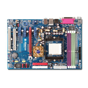
Page 9: Configuration
K8NF4 Series Configuration Layout of K8NF4 Series... -
Page 9: Configuration
K8NF4 Series Configuration Layout of K8NF4 Series... -
Page 10: Hardware Installation
K8NF4 Series Hardware Installation This section will assist you in quickly installing your system hardware. Wear a wrist ground strap before handling components. Electrostatic discharge may damage your system components. CPU Processor Installation ® This mainboard supports AMD Athlon 64/ 64FX processor using a Socket 939. Before building your system, we suggest you visit the AMD website and review the processor installation procedures. -
Page 11: Memory Installation
You can attach the CPU fan to the CPUFAN header. Memory Installation The K8NF4 Series mainboard contain 4 sockets, which use 184- pin DDR SDRAM with a total memory capacity of up to 4 GB. You can install unbuffered DDR400/ 333/ 266(PC3200/ 2700/ 2100) -
Page 11: Memory Installation
You can attach the CPU fan to the CPUFAN header. Memory Installation The K8NF4 Series mainboard contain 4 sockets, which use 184- pin DDR SDRAM with a total memory capacity of up to 4 GB. You can install unbuffered DDR400/ 333/ 266(PC3200/ 2700/ 2100) - Page 12 K8NF4 Series To Enable Dual-Channel DDR, the following conditions must be met: 1.You must use either DIMM1 & DIMM2 together or DIMM3 & DIMM4 together or all four DIMM slots together. If you want to use only one DIMM, you must use DIMM1 or DIMM3.
- Page 12 K8NF4 Series To Enable Dual-Channel DDR, the following conditions must be met: 1.You must use either DIMM1 & DIMM2 together or DIMM3 & DIMM4 together or all four DIMM slots together. If you want to use only one DIMM, you must use DIMM1 or DIMM3.
-
Page 13: Ram Module Installation
K8NF4 Series RAM Module Installation: The following instructions explains memory module installation for these mainboards: Before install your RAM module, please make sure that the power supply is UNPLUGGED. Pull the white plastic tabs at both ends of the slot away from the slot. -
Page 14: Back Panel Configuration
K8NF4 Series Back Panel Configuration PS/2 Mouse & PS/2 Keyboard Connectors: KB/MS This mainboard provides a standard PS/2 mouse connector and PS/2 Keyboard connector. The pin assignments are described below: PS/2 Mouse Assignment Assignment Data +5 V (fused) No connect... -
Page 14: Back Panel Configuration
K8NF4 Series Back Panel Configuration PS/2 Mouse & PS/2 Keyboard Connectors: KB/MS This mainboard provides a standard PS/2 mouse connector and PS/2 Keyboard connector. The pin assignments are described below: PS/2 Mouse Assignment Assignment Data +5 V (fused) No connect... - Page 15 Front Speaker-out are standard audio ports that provide basic audio functionality. After you install the 5.1 Channel drivers for K8NF4 Series and setup 5.1 channel Audio effect, the three audio ports are enabled for 5.1 channel and supporting two speakers each.
- Page 15 Front Speaker-out are standard audio ports that provide basic audio functionality. After you install the 5.1 Channel drivers for K8NF4 Series and setup 5.1 channel Audio effect, the three audio ports are enabled for 5.1 channel and supporting two speakers each.
-
Page 16: Front Panel Indicator: Sw/Led、Speaker
K8NF4 Series Front Panel Indicator: SW/LED、SPEAKER HD LED (Hard Drive LED Connector) This connector can be attached to an LED on the front panel of a computer case. The LED will flicker during disk activity. This disk activity only applies to those IDE drives directly attached to the system board. -
Page 17: Connectors
K8NF4 Series Connectors Floppy Disk Connector: FDC The mainboard provides a standard floppy disk connector (FDC) that supports 360K, 720K, 1.2M, 1.44M and 2.88M floppy diskettes. This connector supports the floppy drive ribbon cables provided in the packaging. Hard Disk Connectors: IDE1/ IDE2、SATA1/ 2/ 3/ 4 The mainboard has two 32-bit Enhanced PCI IDE Controllers that support Ultra ATA 66, Ultra ATA 100 and Ultra ATA 133. -
Page 18: Headers & Jumpers
K8NF4 Series Headers & Jumpers Front USB Headers (Yellow): USB1/ USB2 This mainboard provides 2 USB headers on the board allowing for 4 additional USB ports. To make use of these headers, you must attach a USB bracket/cable with USB ports (some models will come packaged with a USB 4-port bracket-cable). -
Page 18: Headers & Jumpers
K8NF4 Series Headers & Jumpers Front USB Headers (Yellow): USB1/ USB2 This mainboard provides 2 USB headers on the board allowing for 4 additional USB ports. To make use of these headers, you must attach a USB bracket/cable with USB ports (some models will come packaged with a USB 4-port bracket-cable). - Page 19 K8NF4 Series Infrared Header: IrDA (Optional) This IrDA connector can be configured to support wireless infrared and is used to attach to an infrared sensing device. After the IrDA interface is configured, you can use this connector for connectionless data transfer to and from portable devices such as laptops and PDAs.
- Page 19 K8NF4 Series Infrared Header: IrDA (Optional) This IrDA connector can be configured to support wireless infrared and is used to attach to an infrared sensing device. After the IrDA interface is configured, you can use this connector for connectionless data transfer to and from portable devices such as laptops and PDAs.
- Page 20 K8NF4 Series Clear CMOS Jumper: JP1 The “Clear CMOS” jumper is used when you cannot boot your system due to some CMOS configuration such as a password that is forgotten. This jumper allows you to reset the CMOS configurations, and then reconfigure.
- Page 20 K8NF4 Series Clear CMOS Jumper: JP1 The “Clear CMOS” jumper is used when you cannot boot your system due to some CMOS configuration such as a password that is forgotten. This jumper allows you to reset the CMOS configurations, and then reconfigure.
- Page 21 K8NF4 Series ABS (Albatron BIOS security) Header: BIOSCN1 (Optional) This mainboard includes one ABS header (BIOSCN1) for the ABS card which can provide a second BIOS for the mainboard in case the original BIOS is damaged. To set up the jumper on the ABS card, please refer to figure1.
- Page 21 K8NF4 Series ABS (Albatron BIOS security) Header: BIOSCN1 (Optional) This mainboard includes one ABS header (BIOSCN1) for the ABS card which can provide a second BIOS for the mainboard in case the original BIOS is damaged. To set up the jumper on the ABS card, please refer to figure1.
-
Page 22: Audio Connectors
K8NF4 Series Audio Connectors CD-ROM Audio-In Header: CD-IN This header is used to connect to a CD-ROM / DVD audio cable. Front Panel Audio Header: FRONT AUDIO You can use the Front Panel Audio header (FRONT AUDIO) to connect to a separate audio bracket or to connect to case embedded audio equipment. -
Page 23: Slots
K8NF4 Series SPDIF & FRONT AUDIO bracket (optional) You can connect the bracket to the SPDIF and FRONT AUDIO Headers (This photo can be varied with different models). Slots There is one PCI-Express x16 slot, 3 PCI-Express x1 slots and 2 PCI slots. These slots are designed for expansion cards to complement and enhance the functionality of the mainboard. -
Page 24: Power Supply Attachments
K8NF4 Series Power Supply Attachments ATX Power Connector: ATX_PWR、ATX_12V This mainboard requires two ATX power connections. The first is a 24-pin connector and the second is a 4-pin connector. Attach the 4-pin connector first and then attach the 24-pin connector. Make sure the connectors are secure before applying power. -
Page 25: Chapter 2. Bios Setup
K8NF4 Series Chapter 2. BIOS Setup Introduction This section describes PHOENIX-AWARD™ BIOS Setup program which resides in the ROM BIOS firmware. The Setup program allows users to modify the basic system configuration. The configuration information is then saved to CMOS RAM where the data is sustained by Li-battery after power-down. -
Page 26: Supported Cpus
K8NF4 Series Supported CPUs ® This PHOENIX-AWARD™ BIOS supports the AMD Athlon 64 / 64 FX CPU. Key Function In general, you can use the arrow keys to highlight items, press <Enter> to select, use the <PgUp> and <PgDn> keys to change entries, press <F1> for help and press <Esc> to quit. The following table provides more detail about how to navigate within the BIOS Setup program. -
Page 27: Main Menu
K8NF4 Series Main Menu When you enter the PHOENIX-AWARD™ BIOS Utility, the Main Menu will appear on the screen. The Main menu allows you to select from several configuration options. Use the left/right arrow keys to select a particular configuration screen from the top menu bar or use the down arrow key to access... -
Page 28: Main Menu Setup Configuration Options
K8NF4 Series Main Menu Setup Configuration Options Item Options Description Set the system date. Note that the ‘Day’ automatically Date mm dd yyyy changes when you set the date. Time Hh: mm: ss Set the current time of the system. -
Page 28: Main Menu Setup Configuration Options
K8NF4 Series Main Menu Setup Configuration Options Item Options Description Set the system date. Note that the ‘Day’ automatically Date mm dd yyyy changes when you set the date. Time Hh: mm: ss Set the current time of the system. -
Page 29: Advanced Bios Features
K8NF4 Series Advanced BIOS Features Removable Device Priority Select removable device priority. Just like floppy, LS120, ZIP-100, USB-FDD and USB-ZIP. Hard Disk Boot Priority Select hard disk boot priority. CD-ROM Boot Priority Select CD-ROM boot priority. First /Second/Third Boot Device Select the order in which devices will be searched in order to find a boot device. -
Page 30: Boot Up Floppy Seek
K8NF4 Series Boot Up Floppy Seek When Enabled, the BIOS tests (seeks) floppy drives to determine whether they have 40 or 80 tracks. Only 360-KB floppy drives have 40 tracks. Drives with 720KB, 1.2MB, and 1.44MB capacity all have 80 tracks. Because very few modern PCs have 40-track floppy drives, we recommend that you set this field to “Disabled”. -
Page 31: Apic Mode
K8NF4 Series Typematic Delay (Msec) The delay before keystrokes begin to repeat. Options: 250 (default)、500、750、1000 APIC Mode By enabling this option, “MPS version control for OS” can be configured. Options: Disabled、Enabled (default) MPS Version Control For OS The 1.1 version is the older version that supports 8 more IRQs in the Windows NT environment. -
Page 32: System Bios Cacheable
K8NF4 Series RAS# to CAS# delay (Trcd) Select the DRAM delay time when being read. Options: Auto、2T、3T、4T、5T、6T、7T Row precharge Time (Trp) You can set the time to precharge. Options: Auto、2T、3T、4T、5T、6T、7T 1T/2T Memory Timing Use this item to select the memory timing that you installed. -
Page 33: Pci Express Relative Items
K8NF4 Series PCI / VGA Palette Snoop Some graphic controllers that are not VGA compatible take the output from a VGA controller and map it to their display as a way to provide boot information and VGA compatibility. Options: Disabled (default)、Enabled PCI Latency Timer (CLK) This item allows you to set up the PCI Latency Time (0-255). -
Page 34: Pcie Spread Spectrum
K8NF4 Series HT Ratio This item allows you to set Hyper Transport Frequency. Options: Auto(default)、1x、2x、3x、4x、5x HT Frequency This item displays the result of your HT Ratio setting PCIE Clock This item allows you to select PCIE clock form 100 Mhz(default) to 145Mhz. -
Page 35: Integrated Peripherals
K8NF4 Series Integrated Peripherals Init Display First With systems that have multiple video cards, this option determines whether the primary display uses a PCI slot or an PCIEx slot. Options: PCIEx、PCI Slot (default) IDE Function Setup If you highlight the “IDE Function Setup” label and then press the enter key, it will take you to a... -
Page 36: Ide Prefetch Mode
K8NF4 Series Primary / Secondary /Master / Slave UDMA Ultra DMA 100 functionality can be implemented if it is supported by the IDE hard drives in your system. As well, your operating environment requires a DMA driver (Windows 95 OSR2 or a third party IDE bus master driver). -
Page 37: Onboard Device
K8NF4 Series Onboard Device If you highlight the “Onboard Device” label and then press the enter key, it will take you to a submenu with the following options: OnChip USB This option should be enabled if your system has a USB port installed on the system board. You will need to disable this feature if you add a higher performance controller. -
Page 38: Onboard Fdc Controller
K8NF4 Series Onboard FDC Controller Select “Enabled” if your system has a floppy disk controller (FDC) installed on the system board and you wish to use it. If you install an add-in FDC or the system has no floppy drive, select “Disabled”. -
Page 38: Onboard Fdc Controller
K8NF4 Series Onboard FDC Controller Select “Enabled” if your system has a floppy disk controller (FDC) installed on the system board and you wish to use it. If you install an add-in FDC or the system has no floppy drive, select “Disabled”. -
Page 39: Power Management
K8NF4 Series Power Management The Power Management Setup Menu allows you to configure your system to utilize energy conservation features as well as power-up/ power-down options. ACPI Suspend Type The item allows you to select the suspend type using the ACPI operating system. -
Page 40: Video Off Method
K8NF4 Series Note: If you select Min. or Max. Power Saving modes, the “HDD Power Down” value will fixed. User Define、Min Saving、Max Saving Video Off Method This option determines the manner in which the monitor goes blank. Options: V/H SYNC+Blank This selection will cause the system to turn off the vertical and horizontal synchronization ports and write blanks to the video buffer. -
Page 41: Hardware Monitor
K8NF4 Series RTC Wake Up When “Enabled”, you can set the date and time at which the RTC (real-time clock) alarm awakens the system from Suspend mode. Options: Enabled、Disabled (default). Day of Month Alarm You can choose which date of the month the system will boot up. This field is only configurable when “RTC Wake Up”... -
Page 42: Load Defaults
K8NF4 Series Load Defaults Load System Default Settings Load System Default Settings. Load System Turbo Settings Load System Turbo Settings. Load CMOS From BIOS Load defaults from flash ROM for systems without batteries. Save CMOS To BIOS Save defaults to flash ROM for systems without batteries. -
Page 43: Exit Menu
K8NF4 Series Exit Menu Save & Exit Setup Save all configuration changes to CMOS (memory) and exit setup. A confirmation message will be displayed before proceeding. Exit Without Saving Abandon all changes made during the current session and exit setup. A confirmation message will be... -
Page 44: Chapter 3: Software Setup
K8NF4 Series Chapter 3: Software Setup Software List Category Platform Microsoft DirectX 9.0c Windows 98 /ME /2000 /XP nForce Chipset Driver Windows 2000 /XP Trend PC-Cillin 2004 Windows 98 /ME /2000 /XP Acrobat Reader 5 Windows 98 /ME /2000 /XP Software Installation Place the Driver CD into the CD-ROM drive and the Installation Utility will auto-run. -
Page 44: Chapter 3: Software Setup
K8NF4 Series Chapter 3: Software Setup Software List Category Platform Microsoft DirectX 9.0c Windows 98 /ME /2000 /XP nForce Chipset Driver Windows 2000 /XP Trend PC-Cillin 2004 Windows 98 /ME /2000 /XP Acrobat Reader 5 Windows 98 /ME /2000 /XP Software Installation Place the Driver CD into the CD-ROM drive and the Installation Utility will auto-run. - Page 45 K8NF4 Series Microsoft DirectX – provides software of Microsoft DirectX nForce Chipset Driver – Provides all the drivers needed for the chipset. It also includes the audio driver. Note: We recommend that you install the “nVIDIA IDE SW” during Windows ®...
- Page 45 K8NF4 Series Microsoft DirectX – provides software of Microsoft DirectX nForce Chipset Driver – Provides all the drivers needed for the chipset. It also includes the audio driver. Note: We recommend that you install the “nVIDIA IDE SW” during Windows ®...
-
Page 46: Appendix I: 5.1 Channel Setup
K8NF4 Series Appendix I: 5.1 Channel Setup 1. After get into the system, click the audio icon from the Windows screen. 2. Click Speaker Configuration button, you can see the screen like the picture below. 3. You can choose 2, 4 or 6 channels by your speakers. -
Page 47: Appendix Ii: Raid Setup
K8NF4 Series Appendix II: RAID Setup Introduction to RAID RAID (Redundant Array of Independent Disks) technology is a sophisticated disk management system that manages multiple disk drives. It enhances I/O performance and provides redundancy in order to prevent the loss of data in case of individual disk failure. The RAID facility on this board provides RAID 0, RAID 1, RAID 0+1 and RAID SPAN. -
Page 47: Appendix Ii: Raid Setup
K8NF4 Series Appendix II: RAID Setup Introduction to RAID RAID (Redundant Array of Independent Disks) technology is a sophisticated disk management system that manages multiple disk drives. It enhances I/O performance and provides redundancy in order to prevent the loss of data in case of individual disk failure. The RAID facility on this board provides RAID 0, RAID 1, RAID 0+1 and RAID SPAN. - Page 48 K8NF4 Series NVIDIA RAID Utility Configuration The NVIDIA RAID Utility is used to configure RAID disk management into your hard disks. This section will explain how to setup and maintain your RAID disk drives. Starting up the NVIDIA BIOS RAID Utility...
- Page 48 K8NF4 Series NVIDIA RAID Utility Configuration The NVIDIA RAID Utility is used to configure RAID disk management into your hard disks. This section will explain how to setup and maintain your RAID disk drives. Starting up the NVIDIA BIOS RAID Utility...
- Page 49 K8NF4 Series 0.0.M = PATA1 (master drive) 0.0.S = PATA1 (slave drive) 0.1.M = PATA2 (master drive) 0.1.S = PATA2 (slave drive) 1.0.M = SATA1 1.1.M = SATA2 Creating New RAID Array The first screen you will see upon initial configuration is the “Define New Array” screen. First, tab over to the “RAIDMode”...
- Page 49 K8NF4 Series 0.0.M = PATA1 (master drive) 0.0.S = PATA1 (slave drive) 0.1.M = PATA2 (master drive) 0.1.S = PATA2 (slave drive) 1.0.M = SATA1 1.1.M = SATA2 Creating New RAID Array The first screen you will see upon initial configuration is the “Define New Array” screen. First, tab over to the “RAIDMode”...
- Page 50 K8NF4 Series Next, in the “Free Disks” section, you can use the up/down arrow keys to select disks to be used in your RAID array. After highlighting a disk, use the right-arrow key to activate the disk as part of the RAID Array. The selected disk will move over to the “Array Disks” section. You can use the left-arrow key to reverse your selection.
- Page 50 K8NF4 Series Next, in the “Free Disks” section, you can use the up/down arrow keys to select disks to be used in your RAID array. After highlighting a disk, use the right-arrow key to activate the disk as part of the RAID Array. The selected disk will move over to the “Array Disks” section. You can use the left-arrow key to reverse your selection.
-
Page 51: Deleting An Array
K8NF4 Series Deleting an Array You can delete an existing array on the “Array Detail” screen. Press the <D> key. A warning/confirmation message will display (as shown below). Press <Y> to confirm. After the array is successfully deleted, the screen will display as shown below. -
Page 52: Rebuilding A Raid Mirrored Array
K8NF4 Series Rebuilding a RAID Mirrored Array This section applies to Mirrored or Striped/Mirrored RAID configurations and describes how to reestablish the integrity of a mirrored environment after replacing one of the drives (typically because of a single disk failure). After replacing the errant drive, the rebuild process will move data from its mirrored sibling drive (the drive with information still intact) to the newly installed drive. -
Page 52: Rebuilding A Raid Mirrored Array
K8NF4 Series Rebuilding a RAID Mirrored Array This section applies to Mirrored or Striped/Mirrored RAID configurations and describes how to reestablish the integrity of a mirrored environment after replacing one of the drives (typically because of a single disk failure). After replacing the errant drive, the rebuild process will move data from its mirrored sibling drive (the drive with information still intact) to the newly installed drive. - Page 53 K8NF4 Series Installing RAID Drivers during Windows Installation Installation of RAID drivers is done during the Windows installation. These steps assume that the hard disks have already been connected to either the PATA or SATA connectors. It is also assumed that the BIOS RAID Utility has already been configured (see NVIDIA BIOS RAID Utility Configuration section) and you have begun the Windows operating system installation.
- Page 53 K8NF4 Series Installing RAID Drivers during Windows Installation Installation of RAID drivers is done during the Windows installation. These steps assume that the hard disks have already been connected to either the PATA or SATA connectors. It is also assumed that the BIOS RAID Utility has already been configured (see NVIDIA BIOS RAID Utility Configuration section) and you have begun the Windows operating system installation.
Need help?
Do you have a question about the K8NF4 Series and is the answer not in the manual?
Questions and answers