Table of Contents
Advertisement
Quick Links
Copyright
All rights are reserved. No part of this publication may be reproduced, transmitted,
transcribed, stored in a retrieval system or translated into any language or computer
language, in any form or by any means, electronic, mechanical, magnetic, optical, chemical,
manual or otherwise, without the prior written permission of the company. Brands and
product names are trademarks or registered trademarks of their respective companies.
The vendor makes no representations or warranties with respect to the contents herein and
especially disclaim any implied warranties of merchantability or fitness for any purpose.
Further the vendor reserves the right to revise this publication and to make changes to the
contents herein without obligation to notify any party beforehand. Duplication of this
publication, in part or in whole, is not allowed without first obtaining the vendor's approval in
writing.
Trademark
All the trademarks or brands in this document are registered by their respective owner.
Disclaimer
We make no warranty of any kind with regard to the content of this user's manual. The
content is subject to change without notice and we will not be responsible for any mistakes
found in this user's manual. All the brand and product names are trademarks of their
respective companies.
FCC Compliance Statement
This equipment has been tested and found to comply with the limits of a Class B digital
device, pursuant to Part 15 of the FCC Rules. These limits are designed to provide
reasonable protection against harmful interference in a residential installation. This
equipment generates, uses and can radiate radio frequency energy and, if not installed and
used in accordance with the instructions, may cause harmful interference to radio
communications. Operation of this equipment in a residential area is likely to cause harmful
interference in which case the user will be required to correct the interference at his own
expense. However, there is no guarantee that interference will not occur in a particular
installation.
CE Mark
The device is in accordance with 89/336 ECC-ENC Directive.
K8NF4X-754
120410154M1N
Advertisement
Table of Contents

Related Manuals for Albatron K8NF4X-754


Summary of Contents for Albatron K8NF4X-754
-
Page 1: Fcc Compliance Statement
K8NF4X-754 Copyright All rights are reserved. No part of this publication may be reproduced, transmitted, transcribed, stored in a retrieval system or translated into any language or computer language, in any form or by any means, electronic, mechanical, magnetic, optical, chemical, manual or otherwise, without the prior written permission of the company. - Page 2 K8NF4X-754 nVIDIA ® nForce4-4X Support Socket 754 ® Athlon 64/ Athlon 64 FX Processor User Manual Dimensions (ATX form-factor): 244mm x 202mm ( W x L ) Operating System: Windows® 2000/ XP...
-
Page 3: Packing List
I/O Bracket Bridge Card SATA Power Cord (Optional) SATA Cable (Optional) K8NF4X-754 User Manual K8NF4X-754 Setup Driver CD K8NF4X-754 Quick Installation Guide Symbols The following list explains the convention for symbols that will be used throughout this manual: Attention …... -
Page 4: Table Of Contents
Table of Contents CHAPTER 1. GETTING STARTED .............1 ....................1 NTRODUCTION ....................2 PECIFICATION ....................5 ONFIGURATION Layout of K8NF4X-754 ................5 ................6 ARDWARE NSTALLATION CPU Processor Installation..............6 Memory Installation................7 Back Panel Configuration ..............8 Connectors..................10 Front Panel Headers: SW/LED, SPEAKER ........11 Headers & Jumpers ................12 Audio Configuration ................ -
Page 5: Chapter 1. Getting Started
(PC1600) SDRAMs, and support a total memory capacity of 2 GB. The K8NF4X-754 provides two PCI-E x16 slots which are able to support x16 and x4 mode in individual, and also support users to insert two dual graphics cards for multiple display (up to four separated monitors are able to be used at once). -
Page 6: Specification
Mainboard K8NF4X–754 Specification CPU: Support Socket 754 ® Support AMD Athlon 64/ Athlon 64 FX processor Support Hyper-Transport Link Technology Support 800 MHz FSB (Front Side Bus) frequencies Chipset: ® Main Chipset –nVIDIA nForce4-4X ® I/O Controller –Winbond W83627HF-AW AC’ 97 Aduio Codec – Realtek® ALC655 LAN Controller –... -
Page 7: Universal Serial Bus
Two front USB headers come with this mainboard, support a maximum of four additional USB ports to be set up BIOS: Phoenix-Award™ BIOS Support APM1.2 Support ACPI2.0 power management ABS (Albatron BIOS Security): One BIOSCN1 header, supports the ABS Card (Optional) installation Support BIOS backup... -
Page 8: Watch Dog Timer
Mainboard K8NF4X–754 Green Function: Support Phoenix-Award™ BIOS power management function System Waked from sleeping mode of power saving by touching any keyboard or mouse Hardware Monitor Function: Monitor CPU/ Chassis Fan Speed Monitor CPU and system temperature Monitor system voltages Watch Dog Timer: This function is for detecting the system when it is unable to handle over-clocking configurations during the POST stage. -
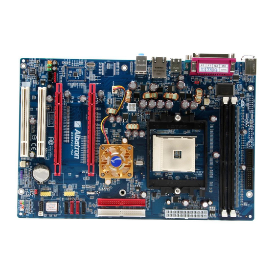
Page 9: Configuration
Mainboard K8NF4X–754 Configuration Layout of K8NF4X-754... -
Page 10: Hardware Installation
Mainboard K8NF4X–754 Hardware Installation This section will assist you quickly in installing your system hardware. Wear a wrist ground strap before handling components. Electrostatic discharge may damage your system components. CPU Processor Installation ® This mainboard supports AMD Athlon 64 processor using a Socket 754. Before building your system, we suggest you to visit the AMD website and review the processor installation procedures. -
Page 11: Memory Installation
Mainboard K8NF4X–754 FAN Headers: CPUFAN, AUXFAN, CHASFAN Three power headers for cooling fans are available on the K8NF4X-754. The cooling fans are playing important roles in maintaining CPU and ambient temperatures in your system. Please attach the fan power cords to these two headers. -
Page 12: Back Panel Configuration
Mainboard K8NF4X–754 2. Align a memory on the socket such that the notch on the memory matches the break on the socket. 3. Lower the memory vertically into the socket and press firmly by using both thumbs until the memory snaps into place. 4. - Page 13 Mainboard K8NF4X–754 PS/2 Mouse & PS/2 Keyboard Ports: KB/MS This mainboard provides a standard PS/2 mouse port and a PS/2 keyboard port. The pin assignments are described below. PS/2 Mouse Assignment Assignment Data +5 V (fused) Clock Ground PS/2 Keyboard Serial and Parallel Interface Ports The mainboard provides one serial port, one parallel port, and one SPDIF out port on the back panel.
-
Page 14: Connectors
Mainboard K8NF4X–754 Audio Ports: Sound This mainboard provides three Audio Ports. The Mic-in, Line-in and Line-out are standard audio ports that provide basic audio function. Line-In (Blue) This port is used to attach an external audio device such as a CD player, tape player or other audio device that has an audio input connector. -
Page 15: Front Panel Headers: Sw/Led, Speaker
Mainboard K8NF4X–754 SATA Connector: SATA1/ SATA2/ SATA3/ SATA4 The four SATA connectors support a transfer rate of 150 Mbps and SATA RAID 0/1/ 0+1/ JBOD mode. One SATA connector only can attach one SATA HDD of each time. Assignment Assignment Ground Ground JSATA1~4... -
Page 16: Headers & Jumpers
Mainboard K8NF4X–754 Reset Switch Header (Blue): RST_SW This header can be attached with a momentary SPST button cord. The switch is normally left open. When the switch closed, it will cause the mainboard to reset and run the POST (Power-On Self Test). Power-on Switch Header (Orange): PWR_SW This header can be attached with a PC front panel power switch cord. - Page 17 Mainboard K8NF4X–754 USB Power Headers: JP2 This header allows you to set the USB power at +5V or +5VSB mode. When you need to use a USB device, you may set it at +5V mode. Otherwise, you may set the USB power at +5VSB mode when you need to use the system wake up function.
-
Page 18: Audio Configuration
Mainboard K8NF4X–754 Audio Configuration CD-ROM Audio-In Connector: CD-IN This header is used to attach a CD-ROM / DVD audio cable. Assignment Left channel input Ground CD-IN Ground Right channel input SPDIF Header: SPDIF S/PDIF is a recent audio transfer file format, which provides high quality audio using optical fiber and digital signals. -
Page 19: Slots
Mainboard K8NF4X–754 Front Audio Connector: FRONT AUDIO If your PC front panel has the audio ports, please remove the jumpers on this header, and then you will have two sets of audio ports (one set is on your PC front panel and the other one is on your PC back panel) to use. -
Page 20: Power Supply Attachments
Mainboard K8NF4X–754 Power Supply Attachments ATX Power Connector: ATX_PWR, ATX_12V Attach power cords on these connectors and make sure they are set in secure before applying the power. Then the system is able to support several functions such as the instant power-on and so on. -
Page 21: Chapter 2. Bios Setup
Mainboard K8NF4X–754 Chapter 2. BIOS Setup Introduction This section describes PHOENIX-AWARD™ BIOS Setup program which resides in the BIOS firmware. The Setup program allows users to modify the basic system configuration. The configuration information is then saved to CMOS RAM where the data is sustained by battery after power-down. -
Page 22: Main Menu
Mainboard K8NF4X–754 Main Menu When you enter the PHOENIX-AWARD™ BIOS Utility, the Main Menu will appear on the screen. The Main menu allows you to select from several configuration options. Use the left/right arrow keys to select a particular configuration screen from the top menu bar or use the down arrow key to access and configure the information below. - Page 23 Mainboard K8NF4X–754 Main Menu Setup Configuration Options Item Options Description Set the system date. Note that the ‘Day’ automatically Date mm dd yyyy changes when you set the date. Time Hh: mm: ss Set the current time of the system. IDE Primary Options contained Press <Enter>...
-
Page 24: Advanced Bios Features
Mainboard K8NF4X–754 Advanced BIOS Features Removable Device Priority Select removable device boot priority. Hard Disk Boot Priority Select hard disk drive boot priority. First /Second/Third Boot Device Select the order in which devices will be searched in order to find a boot device. Options: Removable (default for first boot device), CD ROM (default for second boot device), Hard Disk (default for third boot device), Disabled. -
Page 25: Advanced Bios Features
Mainboard K8NF4X–754 Advanced BIOS Features Virus Warning Set the virus warning feature for IDE hard disk boot sector protection. If the function is enabled, any attempt to write data into this area will cause a beep and warning message display on screen. Options: Disabled (default), Enabled. CPU Internal Cache Make CPU internal cache active or inactive. -
Page 26: Advanced Chipset Features
Mainboard K8NF4X–754 MPS Version Control For OS The 1.1 version is the older version that supports 8 more IRQs in the Windows NT environment. Choose the new 1.4 version for Windows 2000 and Windows XP. Options: 1.4 (default), 1.1. OS Select For DRAM > 64MB Select “OS2”... - Page 27 Mainboard K8NF4X–754 PnP/PCI Configurations PCI / VGA Palette Snoop Some graphic controllers that are not VGA compatible take the output from a VGA controller and map it to their display as a way to provide boot information and VGA compatibility. Options: Disabled (default), Enabled.
- Page 28 Mainboard K8NF4X–754 HT Ratio This item allows you to set Hyper Transport Frequency. Options: 1x, 2x, 3x, 4x, 5x. HT Frequency This item displays the result of your HT Ratio setting. PCIE Clock This item allows you to select PCIE clock form 100 Mhz(default) to 145Mhz. PCIE Spread Spectrum The Spread Spectrum function can reduce the EMI (Electromagnetic Interference) generated.
-
Page 29: Integrated Peripherals
Mainboard K8NF4X–754 Integrated Peripherals Init Display First With systems that have multiple video cards, this option determines whether the primary display uses a PCI slot or an PCIEx slot. Options: PCIEx, PCI Slot (default). IDE Function Setup If you highlight the “IDE Function Setup” label and then press the enter key, it will take you to a submenu with the following options: OnChip IDE Channel 0/1 The mainboard chipset contains a PCI IDE interface with support for two IDE channels. -
Page 30: Onboard Device
Mainboard K8NF4X–754 IDE Prefetch Mode The “onboard” IDE drive interfaces supports IDE prefetching for faster drive access. If you install a primary and/or secondary add-in IDE interface, set this option to “Disabled” if the interface does not support prefetching. Options: Enabled (default), Disabled. IDE HDD Block Mode Block mode is otherwise known as block transfer, multiple commands, or multiple sector read/write. - Page 31 Mainboard K8NF4X–754 AC97 Audio This option allows you to control the onboard AC’97 audio. Options: Enabled (default), Disabled. MAC Lan This option allows you to control the onboard LAN device. Options: Enabled (default), Disabled. Onboard I/O Chip Setup If you highlight the “Onboard I/O Chip Setup” label and then press the enter key, it will take you to a submenu with the following options: Power On Function This field allows you to select a way to power on your computer.
-
Page 32: Power Management
Mainboard K8NF4X–754 EPP Mode Select Select EPP port type 1.7 or 1.9. This field is only configurable if “Parallel Port Mode” is set to “EPP” or “ECP+EPP”. Options: EPP 1.9(default), EPP 1.7. ECP Mode Use DMA Select a DMA Channel for the parallel port when using the ECP mode. This field is only configurable if “Parallel Port Mode”... -
Page 33: Video Off Method
Mainboard K8NF4X–754 Power Management There are three options of Power Management: 1. Min. Power Saving Minimum power management HDD Power Down = 15 minutes 2. Max. Power Saving Maximum power management (only available for sl CPUs). HDD Power Down = 1 minute 3. -
Page 34: Hardware Monitor
Mainboard K8NF4X–754 Ring Wake Up This option allows you to awaken the system upon receiving an incoming call to modem device. Options: Disabled (default), Enabled. USB Wake up This item allows you to awaken the system from suspend mode using a USB devices. Options: Enabled, Disabled (default). -
Page 35: Load Defaults/Exit Menu
Mainboard K8NF4X–754 Load Defaults/Exit Menu Load Defaults Load System Default Settings Load System Default Settings. Load System Turbo Settings Load System Turbo Settings. Load CMOS From BIOS Load defaults from flash ROM for systems without batteries. Save CMOS To BIOS Save defaults to flash ROM for systems without batteries. -
Page 36: Chapter 3: Software Setup
Mainboard K8NF4X–754 Chapter 3: Software Setup Software List Category Platform Microsoft DirectX9.0c Windows 98 /ME /2000 /XP nForce Chipset Driver Windows 2000 /XP Trend PC-Cillin 2005 Windows 98 /ME /2000 /XP Adobe Acrobat Reader 5 Windows 98 /ME /2000 /XP Dr. - Page 37 Mainboard K8NF4X–754 2. Click the “Utilities” and you can choose the software to install. Trend PC-Cillin 2005 – It provides the software of Trend PC-Cillin 2005 (Anti-virus program). Microsoft DirectX9.0c – It provides the software of Microsoft DirectX9.0c. Adobe Acrobat Reader5 – Install this software, you can browse files with pdf format. Dr.
-
Page 38: Chapter 3: Troubleshooting
Mainboard K8NF4X–754 Chapter 3: Troubleshooting Problem 1: No power to the system. Power light does not illuminate. Fan inside power supply does not turn on. Indicator lights on keyboard are not lit. Causes: 1. Power cable is unplugged. 2. Defective power cable. 3. - Page 39 Mainboard K8NF4X–754 Problem 4: System only boots from the CD-ROM. The hard disk can be read and applications can be used but booting from the hard disk is impossible. Causes: Hard Disk boot sector has been corrupted. Solutions: Back up data and applications files. Reformat the hard drive. Re-install applications and data using backup disks.
- Page 40 Mainboard K8NF4X–754 Problem 10: Keyboard failure. Causes: Keyboard is disconnected. Solutions: Reconnect keyboard. Replace keyboard if you continue to experience problems. Problem 11: No color on screen. Causes: 1. Faulty Monitor. 2. CMOS incorrectly set up. Solutions: 1. If possible, connect monitor to another system. If no color appears, replace monitor. 2.
-
Page 41: Appendix I: Super 5.1 Channel Audio Effect Setup
Mainboard K8NF4X–754 Appendix I: Super 5.1 Channel Audio Effect Setup Channels Setup 1. After getting into the system, click the audio icon from the Windows screen. 2. Click Speaker Configuration button, you can see the screen like the picture below. 3. -
Page 42: Appendix Ii: Raid Setup
Mainboard K8NF4X–754 Appendix II: RAID Setup Introduction to RAID RAID (Redundant Array of Independent Disks) technology is a sophisticated disk management system that manages multiple disk drives. It enhances I/O performance and provides redundancy in order to prevent the loss of data in case of individual disk failure. The RAID facility on this board provides RAID 0, RAID 1, RAID 0+1 and RAID SPAN. - Page 43 Mainboard K8NF4X–754 NVIDIA RAID Utility Configuration The NVIDIA RAID Utility is used to configure RAID disk management into your hard disks. This section will explain how to setup and maintain your RAID disk drives. Starting up the NVIDIA BIOS RAID Utility When the system boots up during the POST (Power-On Self Test), you will be given an opportunity to enter the NVIDIA BIOS RAID Utility when the screen prompts you with following message:...
- Page 44 Mainboard K8NF4X–754 0.0.M = PATA1 (master drive) 0.0.S = PATA1 (slave drive) 0.1.M = PATA2 (master drive) 0.1.S = PATA2 (slave drive) 1.0.M = SATA1 1.1.M = SATA2 Creating New RAID Array The first screen you will see upon initial configuration is the “Define New Array” screen. First, tab over to the “RAIDMode”...
- Page 45 Mainboard K8NF4X–754 Next, in the “Free Disks” section, you can use the up/down arrow keys to select disks to be used in your RAID array. After highlighting a disk, use the right-arrow key to activate the disk as part of the RAID Array. The selected disk will move over to the “Array Disks” section. You can use the left-arrow key to reverse your selection.
- Page 46 Mainboard K8NF4X–754 Deleting an Array You can delete an existing array on the “Array Detail” screen. Press the <D> key. A warning/confirmation message will display (as shown below). Press <Y> to confirm. After the array is successfully deleted, the screen will display as shown below.
- Page 47 Mainboard K8NF4X–754 Rebuilding a RAID Mirrored Array This section applies to Mirrored or Striped/Mirrored RAID configurations and describes how to reestablish the integrity of a mirrored environment after replacing one of the drives (typically because of a single disk failure). After replacing the errant drive, the rebuild process will move data from its mirrored sibling drive (the drive with information still intact) to the newly installed drive.
- Page 48 Mainboard K8NF4X–754 ® Install the OS of Windows 2000/XP into your RAID HDDs ® In this section, it will tell you how to install the operating system of Windows 2000/XP into your RAID drives. The installation steps below will assume that your HDDs have already been attached to either the PATA or SATA connectors, and also your BIOS RAID Utility has already been configured (see NVIDIA BIOS RAID Utility Configuration section).
-
Page 49: Appendix Iii: Bridge Card Setup
Mainboard K8NF4X–754 Appendix III: Bridge Card Setup Introduction Through two dual graphics cards installed on the mainboard and its software programs configuration, users can review and process their tasks on four separated monitors at once, further have improved their working performance and efficiency. In addition, via the Bridge Card setup, the improved PCI-Express bandwidth can let users utilizing the PCI-E efforts in more efficient ways. -
Page 50: Appendix Iv: Abs (Albatron Bios Security) Card Setup
Card Setup Introduction The ABS (Albatron BIOS Security) function will provide your BIOS a backup, even when your onboard BIOS has damaged and caused the system that can not be powered on. You can just insert an ABS Card (optional) onto the mainboard header, and through setting the card jumper caps, the enabled ABS function will assist you to recover your onboard BIOS. - Page 51 Mainboard K8NF4X–754 3. Before flashing your onboard BIOS, remember to configure the boot priority of your system first. Set the floopy disk drive for the first priority to boot the system up. (BIOS setting path: Advanced -> Hard Disk Boot Priority -> First Boot Device -> Removable) Put the floppy disk that you made into the floppy disk drive, and power on the system.
- Page 52 Mainboard K8NF4X–754 When your screen shows the section of AWARD BIOS FLASH, a message “Do you want to save BIOS?” will be appeared and you can choose to save the original version of the onboard BIOS into the floppy disk or not. In other words, if your onboard BIOS has damaged, then you should type ‘N’.
- Page 53 Mainboard K8NF4X–754 7. After rebooting the system, get into the BIOS setting and make your system saved with the default mode, then all processes of the flash BIOS procedures will be done. BIOS setting path: Defaults -> Load System Default Settings -> Y BIOS setting path: Exit ->...
- Page 54 Mainboard K8NF4X–754 When your onboard BIOS has recovered, you can choose remove or not remove the ABS Card from the mainboard. [ Remove the ABS Card] Remove the ABS Card from the mainboard while the system is powered off, and remember to set the jumper caps which are on the mainboard BIOSCN1 header with the location of Defaults;...
Need help?
Do you have a question about the K8NF4X-754 and is the answer not in the manual?
Questions and answers