Table of Contents
Advertisement
Quick Links
Copyright
All rights are reserved. No part of this publication may be reproduced, transmitted, transcribed,
stored in a retrieval system or translated into any language or computer language, in any form or by
any means, electronic, mechanical, magnetic, optical, chemical, manual or otherwise, without the
prior written permission of the company. Brands and product names are trademarks or registered
trademarks of their respective companies.
The vendor makes no representations or warranties with respect to the contents herein and especially
disclaim any implied warranties of merchantability or fitness for any purpose. Further the vendor
reserves the right to revise this publication and to make changes to the contents herein without
obligation to notify any party beforehand. Duplication of this publication, in part or in whole, is not
allowed without first obtaining the vendor's approval in writing.
Trademark
All the trademarks or brands in this document are registered by their respective owner.
Disclaimer
We make no warranty of any kind with regard to the content of this user's manual. The content is
subject to change without notice and we will not be responsible for any mistakes found in this user's
manual. All the brand and product names are trademarks of their respective companies.
FCC Compliance Statement
This equipment has been tested and found to comply with the limits of a Class B digital device,
pursuant to Part 15 of the FCC Rules. These limits are designed to provide reasonable protection
against harmful interference in a residential installation. This equipment generates, uses and can
radiate radio frequency energy and, if not installed and used in accordance with the instructions, may
cause harmful interference to radio communications. Operation of this equipment in a residential
area is likely to cause harmful interference in which case the user will be required to correct the
interference at his own expense. However, there is no guarantee that interference will not occur in a
particular installation.
CE Mark
The device is in accordance with 89/336 ECC-ENC Directive.
K8X800 PRO II
120410030M2N
Advertisement
Table of Contents

Related Manuals for Albatron K8X800 PRO II


Summary of Contents for Albatron K8X800 PRO II
-
Page 1: Fcc Compliance Statement
K8X800 PRO II Copyright All rights are reserved. No part of this publication may be reproduced, transmitted, transcribed, stored in a retrieval system or translated into any language or computer language, in any form or by any means, electronic, mechanical, magnetic, optical, chemical, manual or otherwise, without the prior written permission of the company. -
Page 2: Package Contents
COM Port & Game Port Bracket (optional) SPDIF & FRONT AUDIO Port Bracket (optional) SATA Power cord/ SATA Cable (optional) I/O Shield Installation and Setup Driver CD / WinCinema software K8X800 PRO II User Manual Symbols Attention … Following the procedures … Troubleshooting …... -
Page 3: Operating System
K8X800 PRO II ® K8T800 & VT8237 ® Supports Socket 754 AMD Athlon 64 Processor USER Manual Dimensions (ATX form-factor): 244mm x 305mm (WxL) Operating System: ® Supports most popular operating systems: Windows 9X/ME/2000/XP etc. -
Page 4: Table Of Contents
......................2 PECIFICATION ................... 5 UICK ONTENT ABLE ....................... 6 ONFIGURATION Layout of K8X800 PRO II ....................6 ..................6 ARDWARE NSTALLATION CPU Processor Installation ....................7 Memory Installation ......................8 Back Panel Configuration....................11 Front Panel Indicator: SW/LED、PWRLED、SPEAKER..........13 Connectors ........................ -
Page 5: Chapter 1. Getting Started
The K8X800 PRO II provides one AGP Slot for 2X/ 4X/ 8X (1.5V only) AGP cards. The K8X800 PRO II include built in IDE facilities that support Ultra ATA 33/ 66/ 100/ 133. It also includes built in Serial ATA facilities that support SATA RAID 0 or 1 and supports transfer rate to 150 MB/s per channel. -
Page 6: Specification
K8X800 PRO II Mainboard Specification CPU: Supports Socket 754 ® Supports AMD Athlon 64 processor HyperTransport Link - supports 16-bit to be capable of operating up to 800 MHz (1600 MT/s) with a bandwidth of up to 3.2 Gbytes/s in each direction Speed: 33 MHz, 32 bit PCI interface (PCI 2.2 compliant) -
Page 7: Flash Memory
K8X800 PRO II Mainboard Shadow RAM This mainboard is equipped with a memory controller providing shadow RAM and support for ROM BIOS BUS Slots: Provides one AGP slot (1.5V only) Provides six PCI bus slots Flash Memory: Supports flash memory functionality... -
Page 8: Universal Serial Bus
K8X800 PRO II Mainboard Universal Serial Bus: Supports up to eight USB ports for USB interface devices Supports USB 2.0 Enhanced Host Controller Interface (EHCI) and dual USB 1.1 Open Host Controller Interface (OHC1) I/O facilities: One multi-mode Parallel Port capable of supporting the following specifications: 1. -
Page 9: Quick Content Table
K8X800 PRO II Mainboard Quick Content Table Function Content Location Page CPU Socket 754 DIMM 1、2、3 DDR DIMM Sockets ATX_ PWR、ATX_12V ATX Power Connector IDE1/IDE2、SATA1/SATA2 IDE Connectors FDC Connector AGP Slot PCI 1、2、3、4、5、6 PCI Slots CPU FAN、Chassis FAN、 CPUFAN、CHASFAN、AUXFAN Auxiliary FAN Front Panel Indicator SW/LED、PWRLED、SPEAKER... -
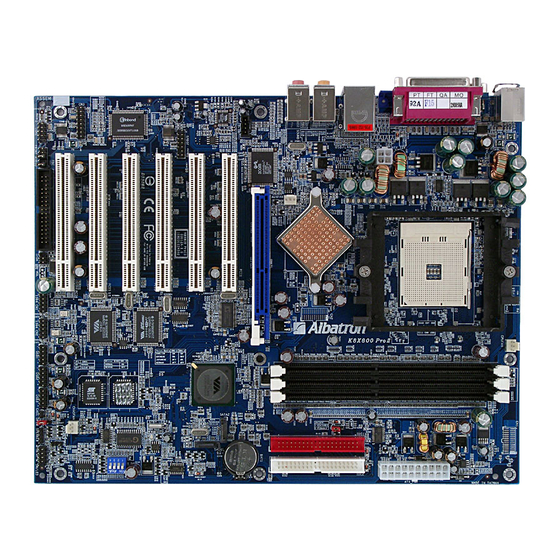
Page 10: Configuration
K8X800 PRO II Mainboard Configuration Layout of K8X800 PRO II Layout of K8X800 PRO II KB/MS CPUFAN PRT/COM ATX_12V IDE1 IDE2 USB/LAN SOUND2 K8T800 SOUND1 AUXFAN 3COM 3C940 CD-IN P C I1 BAT1 1616 SATA1 Vt8237 PCI2 SATA2 PCI3 SPDIF... -
Page 11: Cpu Processor Installation
K8X800 PRO II Mainboard CPU Processor Installation ® This mainboard supports AMD Athlon 64 processor using a Socket 754. Before building your system, we suggest you visit the AMD website and review the processor installation pro cedures. http://www.amd.com CPU Socket 754 Configuration Steps: 1. -
Page 12: Memory Installation
You can attach the CPU fan to the CPUFAN header. Memory Installation he K8X800 PRO II contain 3 sockets, which use 184- pin DDR SDRAM with a total memory pacity of up to 3 GB. You can install unbuffered with (or without) ECC DDR400/ 333/ 266/ 200 C3200/ 2700/ 2100/ 1600) SDRAM. - Page 13 K8X800 PRO II Mainboard Please refer the table below to install the memory DIMMs. DIMM1 DIMM2 DIMM3 DDR400/DDR3 33/DDR 266/D DR200 x8 or x16 Single side x8 or x16 Single side x8 or x16 Single side x8 Do uble side...
-
Page 14: Ram Module Installation
K8X800 PRO II Mainboard RAM Module Installation: Pull the white plastic tabs on each side of the slot away from the slot. Match the notch on the button of the R AM module with the corresponding pattern in the DIMM slot. This ensures that the module is inserted properly. -
Page 15: Back Panel Configuration
USB devices such as: keyboards, mice and other USB devices. You can p lug the USB devices directly into this connector. The K8X800 PRO II also provides a LAN port. You can plug LAN devices directly into this connector. Assignment... - Page 16 K8X800 PRO II Mainboard Serial and Parallel Interface Ports The K8X800 PRO II come equipped with one serial port and on e parallel port on the back panel. The interface ports will be explained below: Print Port COM1 he Serial Interface: COM he serial interface port is sometimes referred to as a RS-232 port or an asynchronous communication port.
-
Page 17: Front Panel Indicator: Sw/Led、Pwrled、Speaker
K8X800 PRO II Mainboard Front Panel In dicator: SW/LED、PWRLED、SPEAKER PWRLED PC_BEEP Ground SPEAKER CHIP Genie oice HD LED (+) Power LE D (+) Hard Driver Power Power LE D (-) HD LED (-) Reset Control (-) Power Bu tton (+) -
Page 18: Connectors
K8X800 PRO II Mainboard onnectors Floppy Disk Connector: FDC The mainboard provides a standard floppy disk connector (FDC) that supports 360K, 720K, 1.2M, 1.44M and 2.88M floppy diskettes. This connector supports the floppy drive ribbon cables provided in the packaging. -
Page 19: Headers & Jumpers
Headers & Jumpers ront USB Headers: USB1/ USB2/ USB3 he K8X800 PRO II also provides three USB headers on the board allowing for 6 more USB ports. hese attach to USB conn ectors embedded into the computer case or connected to a USB bracket (optional). - Page 20 K8X800 PRO II Mainboard Infrared Header: IrDA his IrDA connector can be configured to support wireless infrared and is used to attach to an frared sensing device. After the IrDA interface is configured, you can use this connector for nnectionless data transfer to and from portable devices such as laptops and PDAs.
- Page 21 K8X800 PRO II Mainboard Case Open Warning Header: CASE OPEN his connector is used to notify the user when the computer case has been previously opened. To nfigure this functionality, your computer case must be equipped with a “ case open” cable which ou need to attach to the CASE OPEN header.
- Page 22 K8X800 PRO II Mainboard Voice Genie and BIOS Mirror Function switch: SW1 This switch is used to configure the Voice Genie and BIOS Mirror function s. With SW1-1 and SW1-2, you can select the appropriate language for audio diagnostics. Wit...
-
Page 23: Audio Connectors
K8X800 PRO II Mainboard Audio Connectors Right In ICE SCL ICE SDA PCIRST2- Ground SPMCLKO SPDIFI1 Ground SPDIN Ground Left In SPSCLK SPDIFO1 SPSYNC CD-IN SPMCLKIN SPDIF Ground MIC_VREF Front out_R Rear out_R cket Front out_L Rear out_L FRONT AUDIO... - Page 24 K8X800 PRO II Mainboard S/PDIF Header: SPDIF S/PDIF (Sony/Philips Digital Interface) is an audio transfer file format, which provides high quality audio using optical fiber and digital signals. This mainboard is capable of delivering audio output and receiving au o input through the SPDIF header. One way you would use this header is by using an SPDIF &...
-
Page 25: Slots
K8X800 PRO II Mainboard Slots he slots in this mainboard are designed for expansion cards used to complement and enhance the nctionality of the mainboard. PCI Slots AGP Slot cket CHIP enie Voice GP Slot: AGP he mainboard is equipp ed with a 2X/ 4X/ 8X &... -
Page 26: Chapter 2. Bios Setup
K8X800 PRO II Mainboard Chapter 2. BIOS Setup Introduction his section describes PHOENIX-AWARD™ BIOS Setup program which resides in the ROM BIOS rmware. The Setup program allows users to modify the basic system configuration. The nfiguration information is then saved to CMOS RAM where the data is sustained by Li-battery ter power-down. -
Page 27: Key Function
K8X800 PRO II Mainboard Supported CPUs ® This PHOENIX-AWARD™ BIO S supports the AMD Athlon 64 CPU. Key Function general, you can use the arrow keys to highlight items, press <Enter> to select, use the <PgUp> d <PgDn> keys to change entries, press <F1> for help and press <Esc> to quit. The following table rovides more detail about how to navigate within the BIOS Setup program. -
Page 28: Main Menu
K8X800 PRO II Mainboard Main Menu hen you enter the PHOENIX-AWARD™ BIOS Utility, the Main Menu will appear on the screen. he Main menu allows you to select from several configuration options. Use the left/right arrow keys select a particular configuration screen from the top menu bar or use the down arrow key to access and conf igure the information below. - Page 29 K8X800 PRO II Mainboard Main Menu Setup Configuration Options Item Options Description Set the system date. Note that the ‘Day’ automatically Date mm dd yyyy changes when you set the date. Time Hh: mm: ss Set the current time of the system.
-
Page 30: Advanced Bios Features
K8X800 PRO II Mainboard Advanc ed BIOS Features Rem vable Device iority Select removable dev ice priority. Ju st like floppy, LS120, ZIP-100, USB-FDD and USB-ZIP. Hard Disk Boot Priority Sele ct hard disk boot p riority. CD-ROM Boot Priority... -
Page 31: Boot Up Floppy Seek
K8X800 PRO II Mainboard Boot Up Floppy Seek When Enabled, the BIOS tests (seeks) floppy drives to determine whether they have 40 or 80 tracks. nly 360-KB floppy drives have 40 tracks. Drives with 720KB, 1.2MB, and 1.44MB capacity all ave 80 tracks. -
Page 32: Apic Mode
K8X800 PRO II Mainboard Typematic Rate (Chars/Sec) The rate at which a character repeats when you hold down a key. Options: 6 (default)、8、10、12、15、20、24、30 Typematic Delay (Msec) he delay before keystrokes begin to repeat. Options: 250 (default)、500、750、1000 APIC Mode By enabling this option, “MPS v ersion control for OS”... - Page 33 K8X800 PRO II Mainboard CAS latency This item determines CAS Latency. When synchronous DRAM is installed, the number of clock cycles of CAS latency depends on the DRAM timing . Do not reset this field from the default value ecified by the sys...
-
Page 34: System Bios Cacheable
K8X800 PRO II Mainboard AGP Fast Write The AGP Fast Write technology allows the CPU to write directly to the graphics card bypassing the system AGP 4X speed. Choose “Enable” only when you used with AGP card support. Options: Disabled (default)、Enabled AGP Master 1 WS Write When enabled, writes to the AGP (Accelerated Graphics Port) are executed with one wait state. -
Page 35: Pnp Os Installed
K8X800 PRO II Mainboard PnP/PCI Configurations PNP OS Installed When set to “YES”, BIOS will only in itialize the PnP cards used for the boot sequence (VGA, IDE, ® SCSI). The rest of the cards will be init ialized by the PnP operating system like Windows 95. -
Page 36: Cpu Clock Ratio
K8X800 PRO II Mainboard PCI Latency Timer (CLK) This item allows you to set up the PCI Latency Time (0-255). If you select the “32” it will optimize PCI speeds. Options: 0-255、 32 (default) PCI 1-5 IRQ Assignmen This item allows you to select an IRQ address for your PCI slo t 1-5. - Page 37 K8X800 PRO II Mainboard DDR Speed (strobe/sec) This item display the current DDR speed (CPU Host frequency * Max Memclock ÷ 100.). CPU Speed = Current CPU Host Frequency x CPU Clock Ratio, DDR Speed = Current CPU Host Frequency x (Max Memclock ÷ 100) AGP/PCI Frequency (MHz) This item displays the AGP/PCI Frequency.
-
Page 38: Integrated Peripherals
K8X800 PRO II Mainboard ntegrated Perip herals Init Display First ith systems that have multiple video cards, this option determines whether the primary display uses a PCI slot or an AGP slot. Opt ions: AGP (default)、PIC Slot oice Genie This item allows you to enab led or disabled the Voice Genie. -
Page 39: Ide Dma Transfer Access
K8X800 PRO II Mainboard IDE DMA transfer access This item allows you to enabled or disabled the IDE DMA transfer access. ptions: Enabled (default)、Disabled IDE Channel0/1 he mainboard chipset contains a PCI IDE interface with support for two IDE channels. Select “E... -
Page 40: Usb Controller
K8X800 PRO II Mainboard Onboard Audio Device This option allows you to enabled or disabled the onboard audio device. Options: Enabled (default)、Disabled Onboard LAN Device This option allows you to control the onboard LAN device. Options: Enabled (default)、Disabled nboard 1394 Device This item allows you to control the onboard 1394 device. -
Page 41: Onboard Serial Port 1
K8X800 PRO II Mainboard Onboard Serial Port 1 Select an address and corresponding interrupt for the first serial port. Options: Disabled、3F8/IRQ4 (default)、 2F8/IRQ3、 3E8/IRQ4、 2E8/IRQ3、 Auto Onboard Serial Port 2 Select an address and corresponding interrupt for the second serial port. -
Page 42: Epp Mode Select
K8X800 PRO II Mainboard EPP Mode Select Select EPP port type 1.7 or 1.9. Options: EPP 1.7(default), EPP1.9. ECP Mode Use DMA Select a DMA Channel for the port. Options: 3 (default)、1 Game Port Address Game Port I/O Address. Option s: 201 (default)、209、Disabled... -
Page 43: Power Management
K8X800 PRO II Mainboard Power Management The Power Management Setup Menu allows you to configure your system to utilize energy conservation features as well as power-up/ power-down options. ACPI Suspend Type The item allows you to select the suspend type using the ACPI operating system. -
Page 44: Video Off Method
K8X800 PRO II Mainboard 3. User Defined (default) Allows you to set each mode individually. When this option is enabled, the “suspend mode” time is configurable from 1 minute to 1 hour. The DD Power Down, which ranges from 1 min. to 15 min. and includes a “disable” option. - Page 45 K8X800 PRO II Mainboard Soft-Off by PWRBTN Pressing the power button for more than 4 se conds forces the system to enter the Soft-Off state when the system has “hung.” Options: Delay 4 Sec, Instant-Off (default). Run VGABIOS if S3 R esume elect whether you want to run VGABIOS when the system wakes up from the S3 resume function.
- Page 46 K8X800 PRO II Mainboard LPT & COM When this option is set to On, any event occurring at a COM(serial)/LPT (printer) port will awaken a system which has been suspended. ptions: LPT/COM (default)、COM、LPT、NONE HDD & FDD When set to “On”, any event occurring...
- Page 47 K8X800 PRO II Mainboard IRQs Activity Monitoring Press Enter to access a sub menu used to configure the different wake up events (i.e. wake on LPT & COMM activity). Primary INTR Q3 (COM2) Enabled IRQ4 (COM1) Enabled IRQ5 (LPT2) Enabled...
-
Page 48: Hardware Monitor
K8X800 PRO II Mainboard Hardware Monitor ase Open Warning this function is set to “Enabled” and the case had been previously opened, the system will tomatically display alert messages on the screen when you power on your computer. If this nction is set to “Disabled”, the system will not show alert messages when you power on your... -
Page 49: Load Defaults
K8X800 PRO II Mainboard Load Defaults Load System Default Settings Load System Default Settings. Load System Turbo Settings Load System Turbo Settings. oad CMOS From BIOS Load defaults from flash ROM for systems withou t batteries. Save CMOS To BIOS Save defaults to flash ROM for systems without batteries. -
Page 50: Exit Menu
K8X800 PRO II Mainboard Exit Menu Save & Exit Setup ave all configuration changes to CMOS (memory) and exit setup. A confirmation message will be displayed before proceeding. xit Without Saving Abandon all changes made during the curren t session and exit setup. A confirmation message will be... -
Page 51: Chapter 3: Software Setup
Driver CD. (For more details, please refer to the Readme.txt files that in each folder of the Driver CD.) . The first screen (Main Screen) will display several buttons. Click “K8X800 PRO II”. - Page 52 K8X800 PRO II Mainboard 2. On the next screen, click the drivers that you want to install. 3. If you click the “VIA USB2.0 Driver ” from the screen in step 2, it will display the screen as left. 4. Click on the “3Com940 LAN Driver” item from the screen in step 2.
- Page 53 K8X800 PRO II Mainboard ® New installation of Windows 0/XP using a Serial ATA drive as the boot device. ® Follow the instructions in this section if you are performing a new installation of Windows 2000/XP and you wish to boot from a drive attached to th e SATA co nnector.
-
Page 54: Chapter 4: Troubleshooting
K8X800 PRO II Mainboard hapter 4: Troubleshooting Problem 1: No power to the system. Power light does not illuminate. Fan inside power supply does not turn on. Indicator lights on keyboard are not lit. Causes: 1. Power cable is unplugged. - Page 55 K8X800 PRO II Mainboard Problem 4: System only boots from the CD-ROM. The hard disk can be read and applic ations can be used but booting from the hard disk is impossible. Causes: Hard Disk boot sector has been corrupted.
- Page 56 K8X800 PRO II Mainboard K8X800 PRO II Mainboard roblem 10: board failure. Causes: Keyboard is disconnected. Solutions: Reconnect keyboard. Replace keyboard if you continue to experience problems. Problem 11: No color on screen. Causes: 1. Faulty Monitor. 2. CMOS incorrectly set up.
-
Page 57: Appendix I: 7.1 Channel Setup
K8X800 PRO II Mainboard Appendix I: 7.1 Channel Setup 1. After you have installed the “VIA Audio Driver”, reboot the system. The Audio Icon will be displayed in the lower-right corner of the Windows desktop. Click on the Audio Icon to display the audio configuration screen. -
Page 58: Appendix Ii: Sata Raid 0/1 Setup
K8X800 PRO II Mainboard Appendix II: SATA RAID 0/1 Setup Introduction to RAID (Redundant Array of Independent Disks) RAID technology is a sophisticated disk management system that manages multiple disk drives, enhancing I/O perfor mance and providing redundancy in order to prevent the loss of data in case any of the indiv idual disks fail. -
Page 59: Create Array
K8X800 PRO II Mainboard Create Array The “Create Array” option will allow you to initialize a RAID array. Choose the “Create Array” on the main screen and press <Enter>. The screen below will display. According to your needs, select “RAID 0 for performance” (striping), “RAID 1 for data protection”... - Page 60 K8X800 PRO II Mainboard After the array has been successfully created, one of the screens will display as s hown below according to the type of array you created. RAID 1 mode RAID 0 mode RAID SPAN mode The RAID 0 screen (above) contains the option, “Block Size 64K”. With this option you can manually select the block size for your array.
-
Page 61: Delete Array
K8X800 PRO II Mainboard Delete Array You can delete an existing array with the “Delete Array” option on the main screen. Choose the “Delete Array” option and press <Enter>. Then press the <Enter> key once again and the system will mark all the existing SATA devices with an asterisk (as shown below in the bottom section). - Page 62 K8X800 PRO II Mainboard Se al Number View an choose the “Serial Number View” to view the serial number of the serial ATA device. The serial number is assigned to the device by the man ufacturer. RAID T ool (VIA Raid Tool icon...
Need help?
Do you have a question about the K8X800 PRO II and is the answer not in the manual?
Questions and answers