Table of Contents
Advertisement
Quick Links
KM51G-754
Copyright
All rights are reserved. No part of this publication may be reproduced, transmitted, transcribed,
stored in a retrieval system or translated into any language or computer language, in any form
or by any means, electronic, mechanical, magnetic, optical, chemical, manual or otherwise,
without the prior written permission of the company. Brands and product names are trademarks
or registered trademarks of their respective companies.
The vendor makes no representations or warranties with respect to the contents herein and
especially disclaim any implied warranties of merchantability or fitness for any purpose. Further
the vendor reserves the right to revise this publication and to make changes to the contents
herein without obligation to notify any party beforehand. Duplication of this publication, in part or
in whole, is not allowed without first obtaining the vendor's approval in writing.
Trademark
All the trademarks or brands in this document are registered by their respective owner.
Disclaimer
We make no warranty of any kind with regard to the content of this user's manual. The content
is subject to change without notice and we will not be responsible for any mistakes found in this
user's manual. All the brand and product names are trademarks of their respective companies.
FCC Compliance Statement
This equipment has been tested and found to comply with the limits of a Class B digital device,
pursuant to Part 15 of the FCC Rules. These limits are designed to provide reasonable
protection against harmful interference in a residential installation. This equipment generates,
uses and can radiate radio frequency energy and, if not installed and used in accordance with
the instructions, may cause harmful interference to radio communications. Operation of this
equipment in a residential area is likely to cause harmful interference in which case the user will
be required to correct the interference at his own expense. However, there is no guarantee that
interference will not occur in a particular installation.
CE Mark
The device is in accordance with 89/336 ECC-ENC Directive.
Ver: EG101
Advertisement
Table of Contents

Related Manuals for Albatron KM51G-754


Summary of Contents for Albatron KM51G-754
-
Page 1: Fcc Compliance Statement
KM51G-754 Copyright All rights are reserved. No part of this publication may be reproduced, transmitted, transcribed, stored in a retrieval system or translated into any language or computer language, in any form or by any means, electronic, mechanical, magnetic, optical, chemical, manual or otherwise, without the prior written permission of the company. - Page 2 KM51G-754 nVIDIA GeForce 6100 (nForce4 C51G) & ® nForce 410 (nForce4 MCP51G) Supports Socket 754 AMD Athlon 64/ Sempron Processor User Manual Dimensions (Micro-ATX Form-Factor): 244mm x 219mm ( W x L ) Operating System: Windows® 2000/ XP...
-
Page 3: Packing List
Do not touch any IC chip, lead, connector or other components. Always unplug the AC power when you install or remove any device on the mainboard or when confuguring pins and switches. Packing List KM51G-754 mainboard FDD Cable HDD Cable SATA Cable... -
Page 4: Table Of Contents
Table of Contents CHAPTER 1. GETTING STARTED ............ 0 ....................... 0 NTRODUCTION ....................... 1 PECIFICATION ....................3 ONFIGURATION Layout of KM51G-754..................3 ................... 4 ARDWARE NSTALLATION CPU Processor Installation................5 Memory Installation ..................6 Back Panel Configuration................7 Connectors....................... 9 Front Panel Headers.................. -
Page 5: Specification
64/ Sempron Processor with system bus 800 MHz (1600 MT/s). The KM51G-754 provides two DIMM (Dual In-Line Memory Modules) sockets. It allows you to install 184-pin, non-ECC unbuffered, DDR400(PC3200)/DDR333(2700)/DDR266(PC2100) SDRAMs, and supports to install a total memory capacity of 2GB. -
Page 6: Fdd Connector
Mainboard KM51G-754 Chipset: ® Northbridge Chipset – nVIDIA GeForce 6100 (nForce4 C51G) ® Southbridge Chipset – nVIDIA nForce 410 (nForce4 MCP51G) ® I/O Controller – ITE IT8712F ® AC’ 97 Aduio Codec – Realtek ALC655 ® LAN Controller – Realtek... -
Page 7: Configuration
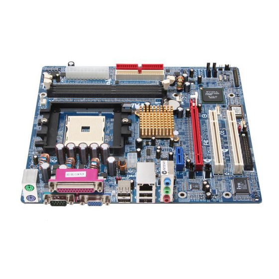
Supports APM1.2 Supports ACPI2.0 power management Green Function: Supports Phoenix-Award™ BIOS power management function Supports system-wake-from-power-saving-mode by keyboard or mouse touching Hardware Monitor Function: Monitors CPU/ Chassis Fan Speed Monitors CPU and system temperatures Monitors system voltages Configuration Layout of KM51G-754... -
Page 8: Hardware Installation
Mainboard KM51G-754 JCFAN1 JKBMS1 JATXPWR1 CPU1 JUSBV1 JUSB1 JATXPWR2 JUSBLAN1 GeForce JFAUDIO1 6100 JAUDIO1 BAT1 PCI-EX1_1 JCDIN1 JSFAN1 Codec PCI-EX16 JSPDIF_OUT1 PCI1 nForce JSATA2 JUSB3 JSATA1 JCI1 PCI2 Super I/O JCMOS1 JUSBV2 BIOS FDD1 JUSB2 JPANEL1 Hardware Installation This section will assist you quickly in installing your system hardware. Wear a wrist ground strap... -
Page 9: Cpu Processor Installation
Mainboard KM51G-754 CPU Processor Installation ® This mainboard supports AMD Athlon 64/ Sempron processor using a Socket 754. Before building your system, we suggest you to visit the AMD website and review the processor installation procedures. (http://www.amd.com) CPU Socket 754 Configuration Steps: 1. -
Page 10: Memory Installation
Memory Installation: DIMM1/2 The KM51G-754 provides two DIMM (Dual In-Line Memory Modules) sockets. It allows you to install 184-pin, non-ECC unbuffered, DDR400(PC3200)/DDR333(2700)/DDR266(PC2100) SDRAMs, and supports to install a total memory capacity of 2GB. -
Page 11: Back Panel Configuration
Mainboard KM51G-754 3. Lower the memory vertically into the socket and press firmly by using both thumbs until the memory snaps into place. 4. Repeat steps 1, 2 & 3 for the remaining memory and DIMM sockets setup. * The pictures shown above are for reference only. The actual installation may vary depending on models. - Page 12 Mainboard KM51G-754 PS/2 Mouse Assignment Assignment Data +5 V (fused) Clock Ground PS/2 Keyboard Serial and Parallel Interface Ports The mainboard provides one serial port, one parallel port, and one VGA port on the back panel. arallel Interface Port: JPRINT1 The parallel port on your system is used to attach a parallel printer or other devices with this interface supported.
-
Page 13: Connectors
Mainboard KM51G-754 Audio Ports: JAUDIO1 This mainboard provides three audio ports, the Mic-in, Line-in and Line-out. These are the standard audio ports that provide basic audio function. Line-In (Blue) This port is for audio input and connects to external audio devices such as CD player, tape player, etc. -
Page 14: Front Panel Headers
Mainboard KM51G-754 Assignment Assignment Ground Ground JSATA1~2 Ground This mainboard supports RAID 0 and 1 mode, refer Appendix II for more information. Attention The FDD/IDE cable is designed and should be attached with a specific direction. One edge of the cable will usually in color such as red, to indicate that should line up with the header pin-1. -
Page 15: Headers & Jumpers
Mainboard KM51G-754 aker Header (Green): SPK A speaker cable on your case front panel can be attached to this header. When you reboot the computer, this speaker will issue a short audible (beep). If there are problems during the Power On Self-Test, the system will issue an irregular pattern of audible beeps through this speaker. - Page 16 Mainboard KM51G-754 Case Open Warning Header: JCI1 This header is used to warn the user when the computer case has been previously opened. To use this function, you have to enable the CASE OPEN warning function in the BIOS Setup Utility.
-
Page 17: Audio Configuration
Mainboard KM51G-754 Audio Configuration CD-ROM Audio-In Connector: JCDIN1 The CD-IN connector is used to attach an audio cable to audio devices such as CD-ROMs, DVD-ROMs etc. Assignment Left channel input Ground JCDIN1 Ground Right channel input SPDIF OUT Connector: JSPDIF_OUT1 S/PDIF is a recent audio transfer file format, which provides high quality audio using optical fiber and digital signals. -
Page 18: Slots
Mainboard KM51G-754 Slots PCI-Express x16 Slot: PCI-Ex16 This mainboard is able to install a graphics card which the PCI-Express x16 interface compatible in this PCI-Ex16 slot. PCI-Express x1 Slot: PCI-Ex1_1 This mainboard is able to install an expansion card which the PCI-Express x1 interface compatible such as network card, SCSI card, etc. -
Page 19: Chapter 2. Bios Setup
Mainboard KM51G-754 Chapter 2. BIOS Setup Introduction This section describes PHOENIX-AWARD™ BIOS Setup program which resides in the BIOS firmware. The Setup program allows users to modify the basic system configuration. The configuration information is then saved to CMOS RAM where the data is sustained by battery after power-down. -
Page 20: Menu Description
Mainboard KM51G-754 Menu Description tandard CMOS Features Include all the adjustable items in standard compatible BIOS. dvanced BIOS Features Include all the adjustable items of Award special enhanced features. dvanced Chipset Features Include all the adjustable items of chipset special features. -
Page 21: Chapter 3: Troubleshooting
Mainboard KM51G-754 Chapter 3: Troubleshooting blem 1: No power to the system. Power light does not illuminate. Fan inside power supply does not turn on. Indicator lights on keyboard are not lit. Causes: 1. Power cable is unplugged. 2. Defective power cable. - Page 22 Mainboard KM51G-754 blem 4: System only boots from the CD-ROM. The hard disk can be read and applications can be used but booting from the hard disk is impossible. Causes: Hard Disk boot sector has been corrupted. Solutions: Back up data and applications files. Reformat the hard drive. Re-install applications and data using backup disks.
- Page 23 Mainboard KM51G-754 blem 10: Keyboard failure. Causes: Keyboard is disconnected. Solutions: Reconnect keyboard. Replace keyboard if you continue to experience problems. blem 11: No color on screen. Causes: 1. Faulty Monitor. 2. CMOS incorrectly set up. Solutions: 1. If possible, connect monitor to another system. If no color appears, replace monitor.
-
Page 24: Appendix I: Super 5.1 Channel Audio Effect Setup
Mainboard KM51G-754 Appendix I: Super 5.1 Channel Audio Effect Setup Channels Setup 1. After starting your system, click the Sound Effect Manager icon from the tool bar on the desktop. You can also find the icon by going to Start-> Setting -> Control Panel. -
Page 25: Appendix Ii: Raid 0/1 Setup
Mainboard KM51G-754 Appendix II: RAID Setup Introduction to RAID RAID (Redundant Array of Independent Disks) technology is a sophisticated disk management system that manages multiple disk drives. It enhances I/O performance and provides redundancy in order to prevent the loss of data in case of individual disk failure. The RAID facility on this mainboard provides RAID 0 and RAID 1. - Page 26 Mainboard KM51G-754 ssociating Screen Drive Names with Physical Drives on the Board This section explains how to associate the drives listed on the “Define a New Array” screen with the physical drives attached to the connectors on the mainboard. This becomes important when identifying drives that need to be replaced or changed.
- Page 27 Mainboard KM51G-754 Next, <Tab> over to the “Striping Block” option and press <Enter>. A pop menu will display as shown below. With this option you can manually select the striping block size for your array. This option will affect data access performance. We recommend that you to select “Optimal”...
- Page 28 Mainboard KM51G-754 After the array has been successfully created, the Array List screen will display as shown below-left. You can press the Enter key to view the RAID details in the “Array Detail” screen. RAID 1 mode (Array List) RAID 1 mode (Array Detail) Deleting an Array You can delete an existing array on the “Array Detail”...
- Page 29 Mainboard KM51G-754 After the array is successfully deleted, the screen will display as shown below. Rebuilding a RAID Mirrored Array This section applies to Mirrored and Striped Mirroring RAID configurations and describes how to reestablish the integrity of a mirrored environment after replacing one of the drives (typically because of a single disk failure).
- Page 30 Mainboard KM51G-754 Launch the NVRAID Management utility by double-clicking the NvRaidMan.exe that has been copied to the C: drive. You can view the status of rebuilding under the Details section from the screen as shown below. ® Install the OS of Windows 2000/XP into your RAID HDDs ®...
Need help?
Do you have a question about the KM51G-754 and is the answer not in the manual?
Questions and answers