Table of Contents
Advertisement
Quick Links
K8X250
Copyright
All rights are reserved. No part of this publication may be reproduced, transmitted, transcribed,
stored in a retrieval system or translated into any language or computer language, in any form
or by any means, electronic, mechanical, magnetic, optical, chemical, manual or otherwise,
without the prior written permission of the company. Brands and product names are trademarks
or registered trademarks of their respective companies.
The vendor makes no representations or warranties with respect to the contents herein and
especially disclaim any implied warranties of merchantability or fitness for any purpose. Further
the vendor reserves the right to revise this publication and to make changes to the contents
herein without obligation to notify any party beforehand. Duplication of this publication, in part or
in whole, is not allowed without first obtaining the vendor's approval in writing.
Trademark
All the trademarks or brands in this document are registered by their respective owner.
Disclaimer
We make no warranty of any kind with regard to the content of this user's manual. The content
is subject to change without notice and we will not be responsible for any mistakes found in this
user's manual. All the brand and product names are trademarks of their respective companies.
FCC Compliance Statement
This equipment has been tested and found to comply with the limits of a Class B digital device,
pursuant to Part 15 of the FCC Rules. These limits are designed to provide reasonable
protection against harmful interference in a residential installation. This equipment generates,
uses and can radiate radio frequency energy and, if not installed and used in accordance with
the instructions, may cause harmful interference to radio communications. Operation of this
equipment in a residential area is likely to cause harmful interference in which case the user will
be required to correct the interference at his own expense. However, there is no guarantee that
interference will not occur in a particular installation.
CE Mark
The device is in accordance with 89/336 ECC-ENC Directive.
Ver: EG101
1
Advertisement
Table of Contents

Subscribe to Our Youtube Channel
Related Manuals for Albatron K8X250


Summary of Contents for Albatron K8X250
-
Page 1: Fcc Compliance Statement
K8X250 Copyright All rights are reserved. No part of this publication may be reproduced, transmitted, transcribed, stored in a retrieval system or translated into any language or computer language, in any form or by any means, electronic, mechanical, magnetic, optical, chemical, manual or otherwise, without the prior written permission of the company. -
Page 2: Packing List
Do not touch any IC chip, lead, connector or other components. Always unplug the AC power when you install or remove any device on the mainboard or when confuguring pins and switches. Packing List K8X250 mainboard FDD Cable HDD Cable I/O Bracket (for ATX case) USB 2.0 cable (optional) - Page 3 K8X250 nVIDIA ® nForce3 250 Support Socket 754 AMD Athlon 64/ Sempron Processor User Manual Dimensions (ATX form-factor): 205mm x 305mm ( W x L ) Operating System: Windows 2000/ XP ®...
-
Page 4: Table Of Contents
Table of Contents CHAPTER 1. GETTING STARTED .............1 ....................... 1 NTRODUCTION ....................... 2 PECIFICATION ....................5 ONFIGURATION Layout of K8X250................... 5 ................... 6 ARDWARE NSTALLATION CPU Processor Installation................6 Memory Installation ..................7 Back Panel Configuration................8 Connectors..................... 10 Front Panel Headers..................11 Headers &... -
Page 5: Chapter 1. Getting Started
SDRAMs, and support a total memory capacity of 2 GB. The K8X250 provides one 8x AGP slot, five 32-bit PCI slots, and one CNR slot (optional). It also provides two IDE connectors for IDE devices with supporting PIO mode 0~4, Bus Master, and Ultra DMA 33/66/100/133. -
Page 6: Specification
Mainboard K8X250 Specification CPU: Support Socket 754 Support AMD Athlon 64/ Sempron processor Support Hyper-Transport Link Technology Support system bus 800 MHz (1600MT/s) Chipset: ® Main Chipset –nVIDIA nForce3 250 I/O Controller –ITE IT8712F AC’ 97 Aduio Codec – Realtek® ALC655 ®... -
Page 7: Usb Port
Mainboard K8X250 Serial ATA Connector: Two SATA connectors, support a maximum of four SATA HDDs to be set up Supports SATA 1.0 specification and provides 150 Mbps transmission speeds Supports RAID 0/1/ 0+1/ JBOD mode Onboard AC’ 97 Sound Codec: High performance Codec with high S/N ratio (>90 db) - Page 8 Mainboard K8X250 Green Function: Supports Phoenix-Award™ BIOS power management functionality Supports system-wake-from-power-saving-mode by keyboard or mouse Hardware Monitor Function: Monitor CPU/ Chassis Fan Speed Monitor CPU and system temperature Monitor system voltages...
-
Page 9: Configuration
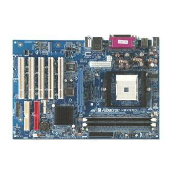
Mainboard K8X250 Configuration Layout of K8X250 JKBMSV1 JCFAN1 JUSBV1 JATXPWR1 JCOM2* JSATA5 JSATA4 JSPDIF_IN (optional) AGP1 JCDIN2 (optional) Super I/O BIOS JCDIN1 JAUDIO1 JUSBV3 BAT1 JUSB2 JUSB1 JCI1 Codec JCMOS1 JSPDIF_OUT (optional) JPANEL1 Note 1: ● stands for pin-1 Note 2: JCOM3 is for optional... -
Page 10: Hardware Installation
Mainboard K8X250 Hardware Installation This section will assist you quickly in installing your system hardware. Wear a wrist ground strap before handling components. Electrostatic discharge may damage your system components. CPU Processor Installation This mainboard supports AMD Athlon 64/ Sempron processor using a Socket 754. -
Page 11: Memory Installation
Memory Installation: DIMM1/DIMM2 The K8X250 provides two 184-pin DIMM (Dual In-Line Memory Module) sockets which support to insert DDR400 (PC3200)/ DDR333 (PC2700)/ DDR266 (PC2100)/ DDR200 (PC1600) SDRAMs and a total memory capacity of 2 GB. -
Page 12: Back Panel Configuration
Mainboard K8X250 2. Align a memory on the socket such that the notch on the memory matches the break on the socket. 3. Lower the memory vertically into the socket and press firmly by using both thumbs until the memory snaps into place. - Page 13 Mainboard K8X250 PS/2 Mouse & PS/2 Keyboard Ports: JKBMS1 This mainboard provides a standard PS/2 mouse port and a PS/2 keyboard port. The pin assignments are described below. PS/2 Mouse Assignment Assignment Data +5 V (fused) Clock Ground PS/2 Keyboard...
-
Page 14: Connectors
Mainboard K8X250 Audio Ports: JAUDIO This mainboard provides three Audio Ports, the Mic-in, Line-in and Line-out. These are standard audio ports that provide basic audio functionality. Line-In (Blue) This port is for audio input and used to attach an external audio device such as a CD player, tape player, etc. -
Page 15: Front Panel Headers
Mainboard K8X250 Assignment Assignment Ground Ground JSATA4/ JSATA5 Ground This mainboard supports SATA RAID 0/1/0+1/JBOD mode, refer Appendix II for more information. Front Panel Headers: JPANEL1 Function Function Assignment Assignment Sleep control Sleep Button (SLP) Ground Speaker (SPK) Speaker Power LED (+) -
Page 16: Headers & Jumpers
Mainboard K8X250 Hard Drive LED Header (Orange): HLED If your case front panel has a hard drive LED cable, attach it to this header. The LED will flicker when there is hard disk drive activity. Reset Button Header (Red): RST This header can be attached to a momentary SPST switch (reset button) cable on your case front panel. - Page 17 Mainboard K8X250 Front USB Headers: JUSB1/JUSB2 This mainboard provides four USB 1.1/2.0 ports (back panel) that attach to USB devices. There are also two additional USB headers that can be connected by cables to four more USB ports on your PC’s front panel giving you a possible 8 USB ports.
- Page 18 Mainboard K8X250 Power Selection for Keyboard/Mouse: JKBMSV1 Keyboard and mouse attached to the back panel JKBMSV1 ports can awaken the system from sleep mode. In order to enable this functionality, you must adjust the jumper caps on JUKBMSV1 header for +5V or +5VSB mode.
-
Page 19: Audio Configuration
Mainboard K8X250 Audio Configuration Front Audio Connector: JAUDIO1 If your case front panel has audio ports, you can connect them to the Front Audio Header of this mainboard. First, you must remove the jumper caps on this header and then attach the cables from the front panel to the pins on this header. -
Page 20: Slots
Mainboard K8X250 Digital Audio-out Connector: SPDIF_IN (optional) Attach the cords from the SPDIF card (optional) onto this connector can use for inputing digital audio. Assignment SPDIF IN JSPDIF_IN Ground Slots Accelerated Graphics Port Slot: AGP1 The mainboard supports to install a graphics card with AGP interface or PCI interface for display. -
Page 21: Chapter 2. Bios Setup
Mainboard K8X250 Assignment Assignment +12V Ground JATXPWR2 +12V Ground Attention In general, power cords are designed and should be attached with a specific direction. The black wire of the power cord is Ground and should be attached onto the header location of Ground. -
Page 22: Menu Description
Mainboard K8X250 Keystroke Function Up arrow Move to previous option Down arrow Move to next option Left arrow Move to the option on the left (menu bar) Right arrow Move to the option on the right (menu bar) Main Menu: Quit without saving changes... - Page 23 Mainboard K8X250 Voltage Control It is for setting the CPU clock and frequency ratio. Load Optimized Defaults It can load the preset system parameter values to set the system in its best performance configurations. Set Supervisor Password Set change or disable password. It allows you to limit access to the system and/or BIOS setup.
-
Page 24: Chapter 3: Troubleshooting
Mainboard K8X250 Chapter 3: Troubleshooting Problem 1: No power to the system. Power light does not illuminate. Fan inside power supply does not turn on. Indicator lights on keyboard are not lit. Causes: 1. Power cable is unplugged. 2. Defective power cable. - Page 25 Mainboard K8X250 Problem 4: System only boots from the CD-ROM. The hard disk however can be read and applications can be used but booting from the hard disk is impossible. Causes: Hard Disk boot sector has been corrupted. Solutions: Back up data and applications files. Reformat the hard drive. Re-install applications and data using backup disks.
- Page 26 Mainboard K8X250 Problem 10: Keyboard failure. Causes: Keyboard is disconnected. Solutions: Reconnect keyboard. Replace keyboard if you continue to experience problems. Problem 11: No color on screen. Causes: 1. Faulty Monitor. 2. CMOS incorrectly set up. Solutions: 1. If possible, connect monitor to another system. If no color appears, replace monitor.
-
Page 27: Appendix I: Super 5.1 Channel Audio Effect Setup
Mainboard K8X250 Appendix I: Super 5.1 Channel Audio Effect Setup Channels Setup 1. After starting your system, click the Sound Effect Manager icon from the tool bar on the desktop. You can also find the icon by going to Start-> Setting -> Control Panel. -
Page 28: Appendix Ii: Raid Setup
Mainboard K8X250 Appendix II: RAID Setup Introduction to RAID RAID (Redundant Array of Independent Disks) technology is a sophisticated disk management system that manages multiple disk drives. It enhances I/O performance and provides redundancy in order to prevent the loss of data in case of individual disk failure. The RAID facility on this board provides RAID 0, RAID 1, RAID 0+1 and RAID SPAN. - Page 29 Mainboard K8X250 NVIDIA RAID Utility Configuration The NVIDIA RAID Utility is used to configure RAID disk management into your hard disks. This section will explain how to setup and maintain your RAID disk drives. Starting up the NVIDIA BIOS RAID Utility...
- Page 30 Mainboard K8X250 Creating New RAID Array The first screen you will see upon initial configuration is the “Define New Array” screen. First, tab over to the “RAIDMode” text box and press <Enter>. The pop up menu will display as shown below.
- Page 31 Mainboard K8X250 Next, in the “Free Disks” section, you can use the up/down arrow keys to select disks to be used in your RAID array. After highlighting a disk, use the right-arrow key to activate the disk as part of the RAID Array. The selected disk will move over to the “Array Disks” section. You can use the left-arrow key to reverse your selection.
- Page 32 Mainboard K8X250 Deleting an Array You can delete an existing array on the “Array Detail” screen. Press the <D> key. A warning/confirmation message will display (as shown below). Press <Y> to confirm. After the array is successfully deleted, the screen will display as shown below.
- Page 33 Mainboard K8X250 Rebuilding a RAID Mirrored Array This section applies to Mirrored or Striped/Mirrored RAID configurations and describes how to reestablish the integrity of a mirrored environment after replacing one of the drives (typically because of a single disk failure). After replacing the errant drive, the rebuild process will move data from its mirrored sibling drive (the drive with information still intact) to the newly installed drive.
- Page 34 Mainboard K8X250 ® Install the OS of Windows 2000/XP into your RAID HDDs ® In this section, it will tell you how to install the operating system of Windows 2000/XP into your RAID drives. The installation steps below will assume that your HDDs have already been attached to either the PATA or SATA connectors, and also your BIOS RAID Utility has already been configured (see NVIDIA BIOS RAID Utility Configuration section).
Need help?
Do you have a question about the K8X250 and is the answer not in the manual?
Questions and answers