Table of Contents
Advertisement
Quick Links
FCC Information and Copyright
This equipment has been tested and found to comply with the limits of a Class B
digital device, pursuant to Part 15 of the FCC Rules. These limits are designed to
provide reasonable protection against harmful interference in a residential
installation. This equipment generates, uses and can radiate radio frequency
energy and, if not installed and used in accordance with the instructions, may
cause harmful interference to radio communications. There is no guarantee that
interference will not occur in a particular installation.
The vendor makes no representations or warranties with respect to the contents
here and specially disclaims any implied warranties of merchantability or fitness
for any purpose. Further the vendor reserves the right to revise this publication
and to make changes to the contents here without obligation to notify any party
beforehand.
Duplication of this publication, in part or in whole, is not allowed without first
obtaining the vendor's approval in writing.
The content of this user's manual is subject to be changed without notice and we
will not be responsible for any mistakes found in this user's manual. All the brand
and product names are trademarks of their respective companies.
i
Advertisement
Table of Contents

Related Manuals for Albatron K8X250GB PRO


Summary of Contents for Albatron K8X250GB PRO
- Page 1 FCC Information and Copyright This equipment has been tested and found to comply with the limits of a Class B digital device, pursuant to Part 15 of the FCC Rules. These limits are designed to provide reasonable protection against harmful interference in a residential installation.
-
Page 2: Table Of Contents
CONTENTS Chapter 1: Introduction ............ 1 K8250GB PRO Features ............. 1 Package Checklist ............... 4 Layout of K8250GB PRO............. 5 Components of K8250GB PRO ........... 6 Chapter 2: Hardware Installation ........7 Central Processing Unit (CPU) ..........7 Fan Headers ................ 9 Memory Modules Installation .......... -
Page 3: Chapter 1: Introduction
CHAPTER 1: INTRODUCTION K8250GB PRO F EATURES A. Hardware Supports Socket 754. Supports the AMD Athlon 64 Socket 754 processor Supports AMD Sempron Socket 754 processor Chipset NVIDIA NF3 250Gb. Hyper Transport link to the AMD Athlon 64 CPU. Supports AGP 3.0 8x interface. Supports system and power management. - Page 4 Super I/O Chip: ITE IT8712F. Low Pin Count Interface. Provides the most commonly used legacy Super I/O functionality. Environment Control initiatives, H/W Monitor Fan Speed Controller ITE's "Smart Guardian" function On Board IDE Supports 4 IDE disk drives. Supports PIO mode 5, Block Mode and Ultra DMA 33/66/100/133 bus master mode.
- Page 5 Storage NVIDIA RAID Technology RAID 0 disk striping for highest system and application performance RAID 1 disk mirroring support for fault tolerance Support for both SATA and ATA-133 disk controller standards RAID 0+1 disk striping and mirroring for highest performance with fault tolerance On Board AC’97 Sound Codec Chip: ALC655...
-
Page 6: Package Checklist
Rear (Back) Side Connectors 1 parallel port. 1RJ-45 LAN jack. 1 audio port. 1 PS/2 keyboard & mouse port. 1 serial ports. 4 USB 2.0 ports. 1394 PS/2 (optional) Mouse Parallel Line In/ Surround Line Out Mic In 1/ COM1 COM3 Base/Center (optional) -
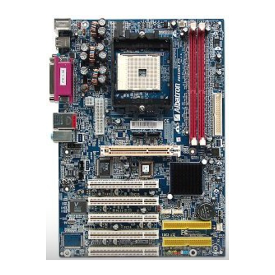
Page 7: Layout Of K8250Gb Pro
K8250GB PRO AYOUT OF Note: ● represents the 1 pin. -
Page 8: Components Of K8250Gb Pro
K8250GB PRO OMPONENTS OF M. IDE1~2: Hard disk connectors. A. JATXPWR1~2: ATX power connectors. B. JUSBV1: Power source for USB1. N. JSFAN1: System fan connector. C. JKBMSV1: Power source for O. JCMOS1: Clear CMOS Header. JKBMS1. D. Back panel connectors. JCI1: Case open Header. -
Page 9: Chapter 2: Hardware Installation
CHAPTER 2: HARDWARE INSTALLATION (CPU) ENTRAL ROCESSING Step 1: Pull the lever sideways away from the socket and then raise the lever up to a 90-degree angle. Step 2: Look for the black cut edge on socket, and the white dot on CPU should point forwards this black cut edge. - Page 10 Step 3: Hold the CPU down firmly, and then close the lever to complete the installation. Step 4: Put the CPU Fan on the CPU and buckle it. Connect the CPU FAN power cable to the JCFAN1. This completes the installation.
-
Page 11: Fan Headers
EADERS CPU FAN Header: JCFAN1 Assignment Ground JCFAN1 +12V FAN RPM rate sense System Fan Header: JSFAN1 Assignment Ground +12V JSFAN1 FAN RPM rate sense Note: The JCFAN1 and JSFAN1support system cooling fan with Smart Fan Control utility. It supports 3 pin head connector. When connecting with wires onto connectors, please note that the red wire is the positive and should be connected to pin#2, and the black wire is Ground and should be connected to GND. -
Page 12: Connectors, & Slots
, & S ONNECTORS LOTS Floppy Disk Connector: FDD1 The motherboard provides a standard floppy disk connector that supports 360K, 720K, 1.2M, 1.44M and 2.88M floppy disk types. This connector supports the provided floppy drive ribbon cables. Hard Disk Connectors: IDE1~2 The motherboard has a 32-bit Enhanced PCI IDE Controller that provides PIO Mode 0~5, Bus Master, and Ultra DMA 33/66/100/133 functionality. -
Page 13: Chapter 3: Headers & Jumpers Setup
CHAPTER 3: HEADERS & JUMPERS SETUP OW TO SETUP UMPERS The illustration shows how to set up jumpers. When the jumper cap is placed on pins, the jumper is “close”, if not, that means the jumper is “open”. Pin opened Pin closed Pin1-2 closed ETAIL... - Page 14 Power Source Selection Headers for USB: JUSBV1/JUSBV3 JUSBV1/JUSBV3 Assignment Description JUSBV1: +5V for USB at the USB1 and JUSBLAN1 connector ports. JUSBV3: +5V for USB at the JUSB Pin 1-2 close 1~2 connector ports. JUSBV1: USB1 and JUSBLAN1 ports powered with standby +5V standby voltage of +5V Voltage...
- Page 15 CD-ROM Audio-in Connector: JCDIN1 This connector allows user to connect the audio source from the veriaty devices, like CD-ROM, DVD-ROM, PCI sound card, PCI TV turner card etc.. Assignment Left channel input Ground Ground JCDIN1 Right channel input Front Panel Connector: JPANEL1 This 24-pin connector includes Power-on, Reset, HDD LED, Power LED, Sleep button, speaker and IrDA Connection.
- Page 16 Close CMOS Header: JCMOS1 By placing the jumper on pin2-3, it allows user to restore the BIOS safe setting and the CMOS data, please carefully follow the procedures to avoid damaging the motherboard. JCMOS1 Assignment Normal Operation (Default). Pin 1-2 close Clear CMOS data.
-
Page 17: Chapter 4: Useful Help
CHAPTER 4: USEFUL HELP BIOS B WARD Beep Sound Meaning One long beep followed by two short Video card not found or video card beeps memory bad High-low siren sound CPU overheated System will shut down automatically One Short beep when system No error found during POST boot-up Long beeps every other second... -
Page 18: Chapter 5: Nvidia Raid Function
CHAPTER 5: NVIDIA RAID FUNCTION PERATION YSTEM Windows XP home Edition Windows XP Professional Edition Windows 2000 Professional RRAYS NVRAID supports the following types of RAID arrays: RAID 0: RAID 0 defines a disk striping scheme that improves disk read and writes times for many applications. -
Page 19: How Raid Works
RAID W ORKS RAID 0: The controller “stripes” data across multiple drives in a RAID 0 array system. It breaks up a large file into smaller blocks and performs disk reads and writes across multiple drives in parallel. The size of each block is determined by the strip size parameter, which you set during the creation of the RAID set based on the system environment. - Page 20 RAID 1: Every read and write is actually carried out in parallel across 2 disk drives in a RAID 1 array system. The mirrored (backup) copy of the data can reside on the same disk or on a second redundant drive in the array. RAID 1 provides a hot-standby copy of data if the active volume or drive is corrupted or becomes unavailable because of a hardware failure.
- Page 21 RAID 0+1: RAID 0 drives can be mirrored suing RAID 1 techniques. Resulting in a RAID 0+1 solution for improved performance plus resiliency. Features and Benefits Drives: Minimum 4, and maximum is 6 or 8, depending on the platform. Benefits: Optimizes for both fault tolerance and performance, allowing for automatic redundancy.
- Page 22 Spanning (JBOD): JBOD stands for “Just a Bunch of Disks”. Each drive is accessed as if it were on a standard SCSI host bus adapter. This is useful when a single drive configuration is needed, but it offers no speed improvement or fault tolerance.
Need help?
Do you have a question about the K8X250GB PRO and is the answer not in the manual?
Questions and answers