Table of Contents
Advertisement
KM51PV-754
Copyright
All rights are reserved. No part of this publication may be reproduced, transmitted, transcribed,
stored in a retrieval system or translated into any language or computer language, in any form
or by any means, electronic, mechanical, magnetic, optical, chemical, manual or otherwise,
without the prior written permission of the company. Brands and product names are trademarks
or registered trademarks of their respective companies.
The vendor makes no representations or warranties with respect to the contents herein and
especially disclaim any implied warranties of merchantability or fitness for any purpose. Further
the vendor reserves the right to revise this publication and to make changes to the contents
herein without obligation to notify any party beforehand. Duplication of this publication, in part or
in whole, is not allowed without first obtaining the vendor's approval in writing.
Trademark
All the trademarks or brands in this document are registered by their respective owner.
Disclaimer
We make no warranty of any kind with regard to the content of this user's manual. The content
is subject to change without notice and we will not be responsible for any mistakes found in this
user's manual. All the brand and product names are trademarks of their respective companies.
FCC Compliance Statement
This equipment has been tested and found to comply with the limits of a Class B digital device,
pursuant to Part 15 of the FCC Rules. These limits are designed to provide reasonable
protection against harmful interference in a residential installation. This equipment generates,
uses and can radiate radio frequency energy and, if not installed and used in accordance with
the instructions, may cause harmful interference to radio communications. Operation of this
equipment in a residential area is likely to cause harmful interference in which case the user will
be required to correct the interference at his own expense. However, there is no guarantee that
interference will not occur in a particular installation.
CE Mark
The device is in accordance with 89/336 ECC-ENC Directive.
Ver: EG100
Advertisement
Table of Contents

Subscribe to Our Youtube Channel
Related Manuals for Albatron KM51PV-754


Summary of Contents for Albatron KM51PV-754
-
Page 1: Fcc Compliance Statement
KM51PV-754 Copyright All rights are reserved. No part of this publication may be reproduced, transmitted, transcribed, stored in a retrieval system or translated into any language or computer language, in any form or by any means, electronic, mechanical, magnetic, optical, chemical, manual or otherwise, without the prior written permission of the company. - Page 2 KM51PV-754 nVIDIA nForce4 C51PV & MCP51 ® Supports Socket 754 Athlon 64/ Sempron Processor ® User’s Manual Dimensions (Micro-ATX Form-Factor): 220mm x 244mm ( W x L ) Operating System: Windows® 2000/ XP...
-
Page 3: Packing List
Do not touch any IC chip, lead, connector or other components. Always unplug the AC power when you install or remove any device on the mainboard or when confuguring pins and switches. Packing List KM51PV-754 mainboard Mainboard User’s Manual CD I/O Bracket Mainboard Setup Driver CD... -
Page 4: Table Of Contents
Table of Contents CHAPTER 1. GETTING STARTED ............ 1 ....................... 1 NTRODUCTION ....................... 2 PECIFICATION ....................5 ONFIGURATION Layout of KM51PV-754 .................. 5 ................... 6 ARDWARE NSTALLATION CPU Processor Installation................6 Memory Installation ..................7 Back Panel Configuration................8 Connectors..................... 10 Front Panel Headers.................. -
Page 5: Chapter 1. Getting Started
The mainboard provides one PCI-E x16 slot, one PCI-E x1 slot and two PCI slots for use with a graphics card or expansion cards which the interfaces are compatible. The KM51PV-754 provides one floppy disk drive connector that can be used with 360KB/ 720KB/1.2MB/1.44MB/2.88MB drives. It also has two IDE connectors for hard drives supporting Ultra ATA 66/100/133. -
Page 6: Specification
Mainboard KM51PV-754 Specification CPU: Supports Socket 754 Supports AMD Athlon 64/ Sempron Processor Supports Hyper-Transport Link Technology Supports 800 MHz (1600MT/s) FSB (Front Side Bus) Frequencies Chipset: ® ® Northbridge Chipset – nVIDIA nForce4 C51PV ( nVIDIA GeForce 6150) ®... -
Page 7: Ide Connector
Mainboard KM51PV-754 IDE Connector: Two IDE connectors, support up to four IDE devices can be set Supports Ultra ATA 33/66/100/133 Supports high capacity hard disk drives Serial ATA II Connector: Four SATA II connectors, support up to four SATA II HDDs can be set Supports SATA 2.0 specification and provides 300 Mbps transmission speeds... -
Page 8: Flash Memory
This function is used for detecting the system hangs during the POST stage due to conflicts resulting from changing the system BIOS settings. Once the problem is detected, the system will reset the configurations and reboot the system within five seconds. ABS (Albatron BIOS Security): Supports ABS Card (Optional) Supports BIOS backup... -
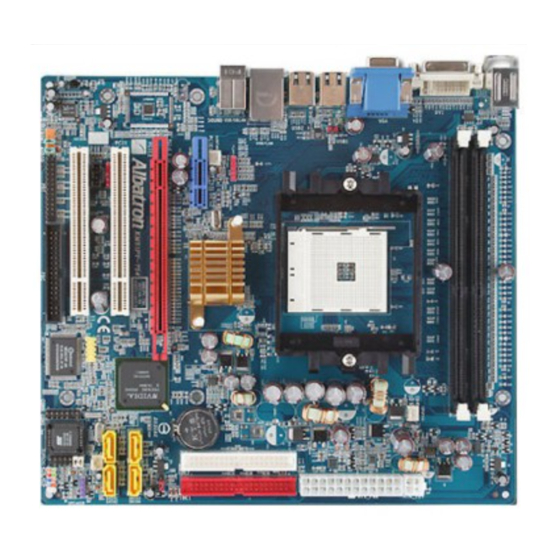
Page 9: Configuration
Mainboard KM51PV-754 Configuration Layout of KM51PV-754... -
Page 10: Hardware Installation
Mainboard KM51PV-754 Hardware Installation This section will assist you in quickly installing your system hardware. Wear a wrist ground strap before handling components. Electrostatic discharge may damage your system components. CPU Processor Installation This mainboard supports AMD Athlon 64/ Sempron processor using Socket 754. -
Page 11: Memory Installation
Memory Installation: DIMM1/2 The KM51PV-754 provides two DIMM (Dual In-Line Memory Modules) sockets. It allows you to install 184-pin, non-ECC, and unbuffered DDR400(PC3200)/ DDR333(2700)/ DDR266(PC2100) SDRAMs, and supports to install a total memory capacity of 2GB. -
Page 12: Back Panel Configuration
Mainboard KM51PV-754 2. Align a memory on the socket such that the notch on the memory matches the break on the socket. 3. Lower the memory vertically into the socket and press firmly by using both thumbs until the memory snaps into place. - Page 13 Mainboard KM51PV-754 DVI & VGA Connectors: DVI, VGA The mainboard provides one DVI connector and one VGA connector on the case back panel. DVI connector delivers the digital signals, and is able to connect with LCD display, plasma display, or other display device which with the DVI interface compatible.
-
Page 14: Connectors
Mainboard KM51PV-754 Connectors Floppy Disk Drive Connector: FDC The mainboard provides a standard floppy disk drive connector (FDC) that supports 360KB/ 720KB/1.2MB/1.44MB/2.88MB floppy disk drives using a FDD ribbon cable. Hard disk drive Connectors: The mainboard provides two IDE connectors that support Ultra ATA 66/100/133 IDE devices. -
Page 15: Front Panel Headers
Mainboard KM51PV-754 Front Panel Headers: FPSWLED1, SPEAKER FPSWLED1 Function Function Assignment Assignment HDD LED (+) Power LED (+) Hard Drive LED Power LED (HD_LED) (ACPI_LED) HDD LED (-) Power LED (-) Reset Control (-) Power Switch (+) Reset Switch Power-on Switch... -
Page 16: Headers & Jumpers
Mainboard KM51PV-754 Headers & Jumpers Front USB Header: USB3 This mainboard provides six onboard USB 1.1/2.0 ports (back panel) that attach to USB devices. There is one additional USB header that can be connected by a cable to two more USB ports on your case front panel giving you a possible 8 USB ports. - Page 17 Mainboard KM51PV-754 Serial Interface Header: CONN_COM1 This mainboard provides a CONN_COM1 header for you connecting an external serial connector on your case back panel. Attach the serial connector cable (Optional) onto this header, then you can use this serial connector to attach with a mic, modem or other peripheral device.
- Page 18 Mainboard KM51PV-754 USB Power Selection Header: JP3 USB devices attached to the back panel USB ports can awaken the system from sleep mode. In order to enable this functionality, you must adjust the jumper caps on JP3 header for +5V or +5VSB mode depending on which USB port that the USB device is attached to.
-
Page 19: Audio Configuration
Mainboard KM51PV-754 Audio Configuration CD-ROM Audio-In Connector: CD-IN The CD-IN connector is used to attach an audio cable to audio devices such as CD-ROMs, DVD-ROMs etc. Assignment Left channel input Ground CD-IN Ground Right channel input SPDIF Header: SPDIF S/PDIF is a recent audio transfer file format, which provides high quality audio using optical fiber and digital signals. -
Page 20: Slots
Mainboard KM51PV-754 Front Audio Connector: FRONT AUDIO If your case front panel has audio ports, you can connect them to the Front Audio Header of this mainboard. First, you must remove the jumper caps on this header and then attach the cables from the front panel to the pins on this header. -
Page 21: Power Supply Attachments
Mainboard KM51PV-754 Power Supply Attachments ATX Power Connector: ATX_PWR, ATX_12V This mainboard provides two ATX power connectors, a 24-pin ATX_PWR connector and a 4-pin ATX_12V connector. You must use a power supply that has both of these connectors and both connectors must be attached before the system is powered on. These power connectors support several power management functions such as the instant power-on function. -
Page 22: Chapter 2. Bios Setup
Mainboard KM51PV-754 Chapter 2. BIOS Setup Introduction This section describes PHOENIX-AWARD™ BIOS Setup program which resides in the BIOS firmware. The Setup program allows users to modify the basic system configuration. The configuration information is then saved to CMOS RAM where the data is sustained by battery after power-down. -
Page 23: Main Menu
Mainboard KM51PV-754 Main Menu When you enter the PHOENIX-AWARD™ BIOS Utility, the Main Menu will appear on the screen. The Main menu allows you to select from several configuration options. Use the left/right arrow keys to select a particular configuration screen from the top menu bar or use the... - Page 24 Mainboard KM51PV-754 Main Menu Setup Configuration Options Item Options Description Set the system date. Note that the ‘Day’ automatically Date mm dd yyyy changes when you set the date. Time Hh: mm: ss Set the current time of the system.
-
Page 25: Advanced Bios Features
Mainboard KM51PV-754 Advanced BIOS Features Removable Device Priority Select removable device boot priority. Hard Disk Boot Priority Select hard disk drive boot priority. First /Second/Third Boot Device Select the order in which devices will be searched in order to find a boot device. -
Page 26: Advanced Bios Features
Mainboard KM51PV-754 Advanced BIOS Features irus Warning This option allows you to choose the Virus Warning feature for IDE Hard Disk boot sector protection. If this function is enabled and a program attempts to write data into this area, BIOS will display a warning message on the screen and sound an audio alarm (beep). -
Page 27: Advanced Chipset Features
Mainboard KM51PV-754 PIC Mode APIC stands for Advanced Programmable Interrupt Controller, and is used to extend the number of available IRQs available in order to avoid sharing conflicts. Options: Disabled, Enabled (Default). PS Version Control For OS The 1.1 version is the older version that supports 8 more IRQs in the Windows NT environment. - Page 28 Mainboard KM51PV-754 S# to CAS# delay (Trcd) This option allows to set the RAS# to CAS# delay to Rd/Wr command on the same bank. Options: Auto, 2T, 3T, 4T, 5T, 6T, 7T. precharge Time (Trp) You can set the Row precharge time. Precharge to Active or Auto-Refresh of the same bank.
- Page 29 Mainboard KM51PV-754 Frequency/Voltage Control PU Speed Detected This option displays the default CPU speed. PU Host Frequency (MHz) This option displays the CPU Host frequency. You can set it from AX to 333. The default depends on your CPU frequency and the CPU installed.
- Page 30 Mainboard KM51PV-754 T Spread Spectrum The Spread Spectrum function can reduce the EMI (Electromagnetic Interference) generated for Hyper Transport. Options: Disabled, Center (Default), Down. CIE Clock This option allows you to select PCIE clock form 100 Mhz (Default) to 145Mhz.
-
Page 31: Integrated Peripherals
Mainboard KM51PV-754 Integrated Peripherals Init Display First With systems that have multiple video cards, this option determines whether the primary display uses a PCI slot or a PCI-E slot. Options: PCI Slot, Onboard, PCIEx. IDE Function Setup If you highlight the “IDE Function Setup” label and then press the enter key, it will take you to a... -
Page 32: Onboard Device
Mainboard KM51PV-754 E Prefetch Mode The “onboard” IDE drive interface supports IDE prefetching for faster drive access. If you install a primary and/or secondary add-in IDE interface, set this option to “Disabled” if the interface does not support prefetching. Options: Enabled (Default), Disabled. - Page 33 Mainboard KM51PV-754 Onboard I/O Chip Setup If you highlight the “Onboard I/O Chip Setup” label and then press the enter key, it will take you to a submenu with the following options: ower On Function This option allows you to select a method of awakening the system from sleep mode.
-
Page 34: Power Management
Mainboard KM51PV-754 Power Management The Power Management Setup Menu allows you to configure your system to utilize energy conservation features as well as power-up/ power-down options. ACPI Suspend Type The item allows you to select the suspend type using the ACPI operating system. -
Page 35: Video Off Method
Mainboard KM51PV-754 Video Off Method This option determines the manner in which the monitor goes blank. Options: V/H SYNC+Blank This selection will cause the system to turn off the vertical and horizontal synchronization ports and write blanks to the video buffer. -
Page 36: Hardware Monitor
Mainboard KM51PV-754 Hardware Monitor This menu is for monitoring the system status such as temperature, voltage, and so on. Load Defaults/Exit Menu Load Defaults Load System Default Settings Load System Default Settings. Load System Turbo Settings Load System Turbo Settings. -
Page 37: Chapter 3: Software Setup
Mainboard KM51PV-754 Chapter 3: Software Setup Software List Category Platform ® Windows 98 /ME /2000 /XP Microsoft DirectX9.0c ® Windows 2000 /XP nForce Chipset Driver ® Windows 2000 /XP nForce Display Driver ® Windows 98 /ME /2000 /XP Realtek Audio Driver... - Page 38 Mainboard KM51PV-754 nForce Display Driver – It provides the driver for being able to display. Realtek Audio Driver – It provides the driver for being able to input/output audio. Attention Please install Microsoft DirectX 9.0c (or the latest version), and then install the nForce Chipset Driver.
-
Page 39: Chapter 4: Troubleshooting
Mainboard KM51PV-754 Chapter 4: Troubleshooting blem 1: No power to the system. Power light does not illuminate. Fan inside power supply does not turn on. Indicator lights on keyboard are not lit. Causes: 1. Power cable is unplugged. 2. Defective power cable. - Page 40 Mainboard KM51PV-754 blem 4: System only boots from the CD-ROM. The hard disk can be read and applications can be used but booting from the hard disk is impossible. Causes: Hard Disk boot sector has been corrupted. Solutions: Back up data and applications files. Reformat the hard drive. Re-install applications and data using backup disks.
- Page 41 Mainboard KM51PV-754 blem 10: Keyboard failure. Causes: Keyboard is disconnected. Solutions: Reconnect keyboard. Replace keyboard if you continue to experience problems. blem 11: No color on screen. Causes: 1. Faulty Monitor. 2. CMOS incorrectly set up. Solutions: 1. If possible, connect monitor to another system. If no color appears, replace monitor.
-
Page 42: Appendix I: Super 5.1 Channel Audio Effect Setup
Mainboard KM51PV-754 Appendix I: Super 5.1 Channel Audio Effect Setup Channels Setup 1. After starting your system, click the Sound Effect Manager icon from the tool bar on the desktop. You can also find the icon by going to Start-> Setting -> Control Panel. -
Page 43: Appendix Ii: Raid Setup
Mainboard KM51PV-754 Appendix II: RAID Setup Introduction to RAID RAID (Redundant Array of Independent Disks) technology is a sophisticated disk management system that manages multiple disk drives. It enhances I/O performance and provides redundancy in order to prevent the loss of data in case of individual disk failure. The RAID facility on this board provides RAID 0, RAID 1, RAID 0+1, RAID JBOD, and RAID 5. - Page 44 Mainboard KM51PV-754 3.On the “RAID config” screen (shown below-right), enable the disks that you want to use as RAID disks (in this example there are four SATA hard drives configured as RAID disks). NVIDIA RAID Utility Configuration The NVIDIA RAID Utility is used to configure RAID disk management into your hard disks. This section will explain how to setup and maintain your RAID disk drives.
- Page 45 Mainboard KM51PV-754 For Example: On a board with 4 connectors (PATA1, PATA2, SATA1, SATA2), the following applies: 0.0.M = PATA1 (master drive) 0.0.S = PATA1 (slave drive) 0.1.M = PATA2 (master drive) 0.1.S = PATA2 (slave drive) 1.0.M = SATA1 1.1.M = SATA2...
- Page 46 Mainboard KM51PV-754 Next, in the “Free Disks” section, you can use the up/down arrow keys to select disks to be used in your RAID array. After highlighting a disk, use the right-arrow key to activate the disk as part of the RAID Array. The selected disk will move over to the “Array Disks” section. You can use the left-arrow key to reverse your selection.
- Page 47 Mainboard KM51PV-754 Deleting an Array You can delete an existing array on the “Array Detail” screen. Press the <D> key. A warning/confirmation message will display (as shown below). Press <Y> to confirm. After the array is successfully deleted, the screen will display as shown below.
- Page 48 Mainboard KM51PV-754 Rebuilding a RAID Mirrored Array This section applies to Mirrored, Striped Mirroring RAID and RAID 5 configurations and describes how to reestablish the integrity of a mirrored environment after replacing one of the drives (typically because of a single disk failure). After replacing the errant drive, the rebuild process will move data from its mirrored sibling drive (the drive with information still intact) to the newly installed drive.
- Page 49 Mainboard KM51PV-754 ® Install the OS of Windows 2000/XP into your RAID HDDs ® In this section, it will tell you how to install the operating system of Windows 2000/XP into your RAID drives. The installation steps below will assume that your HDDs have already been attached to either the PATA or SATA connectors, and also your BIOS RAID Utility has already been configured (see NVIDIA BIOS RAID Utility Configuration section).
-
Page 50: Appendix Iii: Abs (Albatron Bios Security) Card Setup
Appendix III: ABS (Albatron BIOS Security) Card Setup Introduction The ABS (Albatron BIOS Security) system provides your system with a recovery BIOS backup when your onboard BIOS has been damaged beyond system boot capability. Preparation and Setup You should prepare a boot floppy disk and have it ready in case of such BIOS failures. - Page 51 Mainboard KM51PV-754 Place the boot floppy disk (from the “Preparation and Setup” section) into the floppy drive and turn on your system. Note: If your system is not setup to use the floppy drive as the first boot drive, you must enter the BIOS setup utility and make the appropriate adjustments.
- Page 52 Mainboard KM51PV-754 8. The initial AWARD BIOS FLASH screen (shown below-left) will appear and prompt you with the message, “Do you want to save BIOS?” Type “N” (Note: Typing “Y” is only used when saving the BIOS from the onboard BIOS to the floppy disk).
- Page 53 Mainboard KM51PV-754 10. During the next boot sequence, enter the BIOS utility program (Note: During the boot sequence you will be given a chance to enter the BIOS utility by pressing the “DEL” key on most systems). Load the system with the default settings, and save the changes before exit the BIOS utility program.
- Page 54 Mainboard KM51PV-754 11. After you have recovered your onboard BIOS, you can choose to remove or not remove the ABS Card from the mainboard. If you do choose to remove the ABS Card from the mainboard, make sure that the system is powered off before you remove the card.
Need help?
Do you have a question about the KM51PV-754 and is the answer not in the manual?
Questions and answers