Table of Contents
Advertisement
Quick Links
Copyright
All rights are reserved. No part of this publication may be reproduced, transmitted, transcribed,
stored in a retrieval system or translated into any language or computer language, in any form or by
any means, electronic, mechanical, magnetic, optical, chemical, manual or otherwise, without the
prior written permission of the company. Brands and product names are trademarks or registered
trademarks of their respective companies.
The vendor makes no representations or warranties with respect to the contents herein and especially
disclaim any implied warranties of merchantability or fitness for any purpose. Further the vendor
reserves the right to revise this publication and to make changes to the contents herein without
obligation to notify any party beforehand. Duplication of this publication, in part or in whole, is not
allowed without first obtaining the vendor's approval in writing.
Disclaimer
We make no warranty of any kind with regard to the content of this user's manual. The content is
subject to change without notice and we will not be responsible for any mistakes found in this user's
manual. All the brand and product names are trademarks of their respective companies.
FCC Compliance Statement
This equipment has been tested and found to comply with the limits of a Class B digital device,
pursuant to Part 15 of the FCC Rules. These limits are designed to provide reasonable protection
against harmful interference in a residential installation. This equipment generates, uses and can
radiate radio frequency energy and, if not installed and used in accordance with the instructions, may
cause harmful interference to radio communications. Operation of this equipment in a residential
area is likely to cause harmful interference in which case the user will be required to correct the
interference at his own expense. However, there is no guarantee that interference will not occur in a
particular installation.
Ver: EG102
K8SLI
120410146M1N
Advertisement
Table of Contents

Related Manuals for Albatron K8SLI


Summary of Contents for Albatron K8SLI
-
Page 1: Fcc Compliance Statement
However, there is no guarantee that interference will not occur in a particular installation. Ver: EG102 K8SLI 120410146M1N... -
Page 2: Package Contents
Do not touch the IC chips, leads, connectors or other components. Unplug the AC power when you install or remove any device on the mainboard. Package Contents K8SLI mainboard IDE Cable/ FDC Cable SATA Power cord/ SATA Cable USB Bracket (optional) -
Page 3: Operating System
Supports Socket 939 AMD ® Athlon USER Manual Dimensions (ATX form-factor): 194mm x 295mm (WxL) Operating System: Supports most popular operating systems: Windows K8SLI ® nForce4 SLI ® Athlon 64 Processor 64 FX Processor ® 2000/XP etc. -
Page 4: Table Of Contents
CHAPTER 1. GETTING STARTED ...1 ... 1 NTRODUCTION ... 2 PECIFICATION ... 5 ONFIGURATION Layout of K8SLI... 5 ... 6 ARDWARE NSTALLATION CPU Processor Installation ... 6 Memory Installation ... 7 Back Panel Configuration... 10 Front Panel Indicator: SW/LED、SPEAKER ... 13 Connectors ... -
Page 5: Installation Note
INSTALLATION NOTE This mainboard complies with the ATX standard, which means the ACPI connector on this board is 2-pin. If the Power LED cable of your case uses a 3-pin adapter, you must use the 2-pin to 3-pin adapter (contained in the packaging). - Page 6 Locate the Power LED cable attached to the case. If the Power LED cable has a 3-pin adapter, you must use the 2-pin to 3-pin adapter which comes with the packaging. The heads of the power cables usually have a triangular mark which indicates the positive electrode(+).
-
Page 7: Chapter 1. Getting Started
BIOS when the original one is damaged. You don’t have to be worried about what a damaged BIOS may cause. The K8SLI mainboard includes built in IDE facilities that support Ultra ATA 66/ 100/ 133. It also includes built in Serial ATA facilities that support SATA RAID 0/ 1/ 0+1/ JBOD and supports transfer rate to 300 MB/s per channel. -
Page 8: Specification
AC’97 Sound Codec Onboard: High performance CODEC with high S/N ratio (>90 dB) Compliant with AC’97 2.3 specification Integrated S/ PDIF transmitter 6-channel playback capability (5.1 Channel Audio Effect) 3D Stereo enhancement ® 64 / AMD Athlon 64 FX Processor K8SLI... -
Page 9: Universal Serial Bus
Supports Infrared Data Transmissions using IrDA(optional) Supports PS/2 mouse and PS/2 keyboard Supports 360 KB, 720 KB, 1.2 MB, 1.44 MB, and 2.88 MB floppy disk drives Game port compatible (optional) BIOS: Phoenix-Award™ BIOS Supports APM1.2 Supports ACPI power management K8SLI... -
Page 10: Watch Dog Timer
The mainboard contains a special feature called the “Watch Dog Timer” which is used to detect when the system is unable to handle over-clocking configurations during POST stage. Once detected the system will reset the configurations and reboot the system after five seconds K8SLI... -
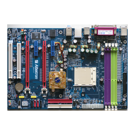
Page 11: Configuration
K8SLI Configuration Layout of K8SLI... -
Page 12: Hardware Installation
Attention Overheating may damage the CPU and other sensitive components. Please check the installation completely before starting the system. Make sure the heatsink and the CPU fan are properly installed. 64/ 64FX processor using a Socket 939. Before building K8SLI... -
Page 13: Fan Headers
You can attach the CPU fan to the CPUFAN header. Memory Installation The K8SLI mainboard contain 4 sockets, which use 184- pin DDR SDRAM with a total memory capacity of up to 4 GB. You can install unbuffered DDR400/ 333/ 266(PC3200/ 2700/ 2100) SDRAM. - Page 14 Double side Double side DDR400 single side single side DDR333 Double side Double side DDR200 single side single side DDR200 Double side Double side DDR200 K8SLI SPEED 2T(default) DDR400 DDR400 DDR400 DDR400 DDR400 DDR400 DDR400 DDR333 DDR400 DDR400 DDR400 DDR400...
-
Page 15: Ram Module Installation
Lower the RAM module into the DIMM Slot and press firmly using both thumbs until the module snaps into place. Repeat steps 1, 2 & 3 for the remaining RAM modules. * The pictures above are for reference only. Your actual installation may vary slightly from the pictures. K8SLI... -
Page 16: Back Panel Configuration
The serial interface port is sometimes referred to as an RS-232 port or an asynchronous communication port. Mice, modems and other peripheral serial devices can be connected to this port. Assignment Data No connect Ground K8SLI Assignment +5 V (fused) Clock No connect... - Page 17 There are four USB connectors on the back panel. These USB connectors are used to attach to USB devices such as: keyboards, mice and other USB devices. You can plug the USB devices directly into this connector. The K8SLI mainboard also provides a GBLAN port. You can plug GBLAN devices directly into this connector.
- Page 18 The K8SLI comes equipped with three Audio Ports. The three ports, Mic-in, Line-in and Front Speaker-out are standard audio ports that provide basic audio functionality. After you install the 5.1 Channel drivers for K8SLI and setup 5.1 channel Audio effect, the three audio ports are enabled for 5.1 channel and supporting two speakers each.
-
Page 19: Front Panel Indicator: Sw/Led、Speaker
K8SLI Front Panel Indicator: SW/LED、SPEAKER HD LED (Hard Drive LED Connector) This connector can be attached to an LED on the front panel of a computer case. The LED will flicker during disk activity. This disk activity only applies to those IDE drives directly attached to the system board. -
Page 20: Connectors
The SATA connectors support transfer rate up to 300 MB/s and SATA RAID 0/ 1/ 0+1/ JBOD mode. The connectors only can connect one serial ATA hard disk device each. This mainboard supports SATA RAID 0/ 1 / 0+1 / JBOD. See appendix Ⅱ for more information. K8SLI... -
Page 21: Headers & Jumpers
This mainboard supports an optional front serial header. To use this header, you can install a COM port & Game Port bracket (optional) with a wire extending to this header. You can then attach your serial device to the serial port on the bracket. K8SLI... - Page 22 K8SLI Infrared Header: IrDA (Optional) This IrDA connector can be configured to support wireless infrared and is used to attach to an infrared sensing device. After the IrDA interface is configured, you can use this connector for connectionless data transfer to and from portable devices such as laptops and PDAs.
- Page 23 But, if you don’t want to use the ABS card, please DO NOT change the positions of the jumper caps and DO NOT remove them. Otherwise, the mainboard and the ABS card might become damaged. K8SLI...
-
Page 24: Clear Cmos Jumper: Jp1
1. Turn off your system and disconnect the AC power cable. 2. Set JP1 to OFF (2-3 Closed). 3. Wait several seconds. 4. Set JP1 to ON (1-2 closed). 5. Connect the AC power cable and turn on your system. 6. Reset your new password. K8SLI... -
Page 25: Audio Connectors
K8SLI Audio Connectors CD-ROM Audio-In Header: CD-IN This header is used to connect to a CD-ROM / DVD audio cable. Front Panel Audio Header: FRONT AUDIO You can use the Front Panel Audio header (FRONT AUDIO) to connect to a separate audio bracket or to connect to case embedded audio equipment. -
Page 26: Slots
PCI-E x 8 slots are for installing PCI-Express graphics cards. PCI-E x 1 slot is for expansion cards which fit the PCI-E x 1 slot. The K8SLI supports SLI technology. See appendix Ⅲ for more information. PCI Slots: PCI1/ PCI2 This mainboard is equipped with 2 standard PCI slots. -
Page 27: Power Supply Attachments
Attention: Please make sure that the 4-pin power cable has plugged in the ATX_12V connector in case that the over load power requirement may damage the mainboard. K8SLI... -
Page 28: Chapter 2. Bios Setup
K8SLI Chapter 2. BIOS Setup Introduction This section describes PHOENIX-AWARD™ BIOS Setup program which resides in the ROM BIOS firmware. The Setup program allows users to modify the basic system configuration. The configuration information is then saved to CMOS RAM where the data is sustained by Li-battery after power-down. -
Page 29: Key Function
Move to next item Move to the item on the left (menu bar) menu Move to the item you desire General help on Setup navigation keys Load previous values from CMOS Load the optimized defaults Save all the CMOS changes and exit K8SLI... -
Page 30: Main Menu
K8SLI Main Menu When you enter the PHOENIX-AWARD™ BIOS Utility, the Main Menu will appear on the screen. The Main menu allows you to select from several configuration options. Use the left/right arrow keys to select a particular configuration screen from the top menu bar or use the down arrow key to access... - Page 31 POST process and notify you. Press <Enter> to enter the sub menu. Displays the amount of conventional memory detected during boot up. Displays the amount of extended memory detected during boot up. Displays the total memory available in the system. K8SLI...
-
Page 32: Advanced Bios Features
K8SLI Advanced BIOS Features Removable Device Priority Select removable device priority. Just like floppy, LS120, ZIP-100, USB-FDD and USB-ZIP. Hard Disk Boot Priority Select hard disk boot priority. CD-ROM Boot Priority Select CD-ROM boot priority. First /Second/Third Boot Device Select the order in which devices will be searched in order to find a boot device. -
Page 33: Quick Power On Self Test
K8SLI Boot Up Floppy Seek When Enabled, the BIOS tests (seeks) floppy drives to determine whether they have 40 or 80 tracks. Only 360-KB floppy drives have 40 tracks. Drives with 720KB, 1.2MB, and 1.44MB capacity all have 80 tracks. Because very few modern PCs have 40-track floppy drives, we recommend that you set this field to “Disabled”. -
Page 34: Advanced Chipset Features
K8SLI Typematic Delay (Msec) The delay before keystrokes begin to repeat. Options: 250 (default)、500、750、1000 APIC Mode By enabling this option, “MPS version control for OS” can be configured. Options: Disabled、Enabled (default) MPS Version Control For OS The 1.1 version is the older version that supports 8 more IRQs in the Windows NT environment. -
Page 35: Reset Configuration Data
PCI device IRQ-7 assigned to: PCI device IRQ-9 assigned to: PCI device IRQ-10 assigned to: PCI device IRQ-11 assigned to: PCI device IRQ-12 assigned to: PCI device IRQ-14 assigned to: PCI device IRQ-15 assigned to: PCI device K8SLI... -
Page 36: Maximum Payload Size
This item display the CPU speed that you setting for. If you don’t change the “CPU Host Frequency” or the “CPU Clock Ratio” and the item will display the current CPU speed. CPU Speed = Current CPU Host Frequency x CPU Clock Ratio, DDR Speed = Current CPU Host Frequency x (Max Memclock ÷ 100) K8SLI... -
Page 37: Pcie Spread Spectrum
Before overclocking, please make sure your system components are capable of overclocking. If you are familiar with the overclocking, we strongly recommend you to set the clock to the defult settings. We do not guarantee that damage will or will not occur when overclocking. K8SLI... -
Page 38: Integrated Peripherals
K8SLI Integrated Peripherals Init Display First With systems that have multiple video cards, this option determines whether the primary display uses a PCI slot or an PCIEx slot. Options: PCIEx、PCI Slot (default) IDE Function Setup If you highlight the “IDE Function Setup” label and then press the enter key, it will take you to a... -
Page 39: Ide Hdd Block Mode
K8SLI Primary / Secondary /Master / Slave UDMA Ultra DMA 100 functionality can be implemented if it is supported by the IDE hard drives in your system. As well, your operating environment requires a DMA driver (Windows 95 OSR2 or a third party IDE bus master driver). -
Page 40: Onboard Device
K8SLI Onboard Device If you highlight the “Onboard Device” label and then press the enter key, it will take you to a submenu with the following options: OnChip USB This option should be enabled if your system has a USB port installed on the system board. You will need to disable this feature if you add a higher performance controller. -
Page 41: Onboard Fdc Controller
This field will determine whether your system will boot after restoring power after a power failure. If you select “On”, the system will boot whether or not the system was on before power failure. If you select “Former-Sts”, the system will be restored to the status before the power failure. Options: Off (default)、On、Former-Sts K8SLI... -
Page 42: Power Management
When this option is enabled, each of the ranges are from 1 minute to 1 hour except for HDD Power Down, which ranges from 1 minute to 15 minute and includes a “disable” option. Power on Suspend POS and STR K8SLI... -
Page 43: Video Off Method
K8SLI Note: If you select Min. or Max. Power Saving modes, the “HDD Power Down” value will fixed. User Define、Min Saving、Max Saving Video Off Method This option determines the manner in which the monitor goes blank. Options: V/H SYNC+Blank This selection will cause the system to turn off the vertical and horizontal synchronization ports and write blanks to the video buffer. -
Page 44: Hardware Monitor
K8SLI RTC Wake Up When “Enabled”, you can set the date and time at which the RTC (real-time clock) alarm awakens the system from Suspend mode. Options: Enabled、Disabled (default). Day of Month Alarm You can choose which date of the month the system will boot up. This field is only configurable when “RTC Wake Up”... -
Page 45: Load Defaults
K8SLI Load Defaults Load System Default Settings Load System Default Settings. Load System Turbo Settings Load System Turbo Settings. Load CMOS From BIOS Load defaults from flash ROM for systems without batteries. Save CMOS To BIOS Save defaults to flash ROM for systems without batteries. -
Page 46: Exit Menu
K8SLI Exit Menu Save & Exit Setup Save all configuration changes to CMOS (memory) and exit setup. A confirmation message will be displayed before proceeding. Exit Without Saving Abandon all changes made during the current session and exit setup. A confirmation message will be... -
Page 47: Chapter 3: Software Setup
Microsoft DirectX 9.0c (or later version) before you install the nForce Chipset Driver. Attention: Please install the Microsoft DirectX 9.0c (or later version) before installing the nForce Chipset Driver. Platform Windows 98 /ME /2000 /XP Windows 2000 /XP Windows 98 /ME /2000 /XP Windows 98 /ME /2000 /XP K8SLI... - Page 48 Acrobat Reader – install Adobe Acrobat Reader program that you can browse pdf files Microsoft DirectX – provides software of Microsoft DirectX If you click the “Browse CD” button, you can browse all the files in the Driver CD. Click “Exit” button to exit the program. K8SLI ®...
-
Page 49: Chapter 4: Troubleshooting
K8SLI Chapter 4: Troubleshooting Problem 1: No power to the system. Power light does not illuminate. Fan inside power supply does not turn on. Indicator lights on keyboard are not lit. Causes: 1. Power cable is unplugged. 2. Defective power cable. - Page 50 K8SLI Problem 4: System only boots from the CD-ROM. The hard disk can be read and applications can be used but booting from the hard disk is impossible. Causes: Hard Disk boot sector has been corrupted. Solutions: Back up data and applications files. Reformat the hard drive. Re-install applications and data using backup disks.
- Page 51 K8SLI Problem 10: Keyboard failure. Causes: Keyboard is disconnected. Solutions: Reconnect keyboard. Replace keyboard if you continue to experience problems. Problem 11: No color on screen. Causes: 1. Faulty Monitor. 2. CMOS incorrectly set up. Solutions: 1. If possible, connect monitor to another system. If no color appears, replace monitor.
-
Page 52: Appendix I: 5.1 Channel Setup
2. Click Speaker Test button, you can see the screen like the pictures below. 3. Select the speaker which you want to test by clicking on it. 2 Channels from the Windows screen. 4 Channels 6 Channels 4 Channels 6 Channels Front Left Rear Left K8SLI Subwoofer Front Right Rear Right Center... -
Page 53: Introduction To Raid
K8SLI Appendix II: RAID Setup Introduction to RAID RAID (Redundant Array of Independent Disks) technology is a sophisticated disk management system that manages multiple disk drives. It enhances I/O performance and provides redundancy in order to prevent the loss of data in case of individual disk failure. The RAID facility on this board provides RAID 0, RAID 1, RAID 0+1 and RAID SPAN. - Page 54 K8SLI NVIDIA RAID Utility Configuration The NVIDIA RAID Utility is used to configure RAID disk management into your hard disks. This section will explain how to setup and maintain your RAID disk drives. Starting up the NVIDIA BIOS RAID Utility...
- Page 55 Next, <Tab> over to the “Striping Block” option and press <Enter>. A pop menu will display as shown below. With this option you can manually select the striping block size for your array. This option will affect data access performance. We recommend that you to select “Optimal” option for automatic configuration. Press <Enter>. K8SLI...
- Page 56 After the array has been successfully created, the Array List screen will display as shown below-left. You can press the Enter key to view the RAID details in the “Array Detail” screen. RAID 1 mode (Array List) RAID 1 mode (Array Detail) K8SLI...
-
Page 57: Deleting An Array
You can delete an existing array on the “Array Detail” screen. Press the <D> key. A warning/confirmation message will display (as shown below). Press <Y> to confirm. After the array is successfully deleted, the screen will display as shown below. K8SLI... -
Page 58: Rebuilding A Raid Mirrored Array
<Y> to confirm. Then press <Ctrl-X> to exit the “NVIDIA RAID Utility” setup. Launch the NVRAID Management utility by double-clicking the NvRaidMan.exe that has been copied to the C: drive. You can view the status of rebuilding under the Details section from the screen as shown below. K8SLI... - Page 59 2000/ XP finishes installing devices, regional settings, networking settings, components, and the final set of tasks. Reboot the system if you are asked to do so. Attention The RAID array can only functions in the Windows ® 2000/ XP installation folders ® 2000/ XP. K8SLI...
-
Page 60: Appendix Ⅲ: Sli (Scalable Link Interface )
SLI-ready PCI Express™ graphics cards at once. SLI-certified graphics cards in a single system System 1 (Heavy) AMD Athlon 64 FX-53 AMD Athlon 64 3400+ nVIDIA 6800 Ultra x2 nVIDIA 6600 GT x2 ≥ 25A ≥500W K8SLI ® System 2 (Light) ≥17A ≥350W... -
Page 61: Installation
SLI-ready graphic card driver. Then just follow the instructions below to set up your SLI function. 1. Click on the little green icon of NVIDIA in the system tray and select the “NVIDIA Display”, the automatically detected monitor brand-model will show up. Just click on it. K8SLI... - Page 62 K8SLI 2. On the next screen (below), select the “SLI multi-GPU” item which is on the left of the sub window. And select the checkbox of “Enable SLI multi-GPU” in the main screen. Click on the “Apply” button to complete...
Need help?
Do you have a question about the K8SLI and is the answer not in the manual?
Questions and answers